1. Introduction
It is about fifty years that the attention to environmental issues significantly affects the planning and development policies of many countries all around the world. On the one hand, more and more different nations participate in international thematic groups and engage in ambitious targets for the reduction of pollution and the rational and efficient use of resources. On the other hand, the welfare of a nation is still too often linked exclusively to industrial development, the objectives of which are often in the opposite direction to the environment care. To reconcile these goals, the concept of sustainable development must be seriously realized. The concept of sustainable development not only considers the ability of a nation to produce wealth while respecting the environment. Indeed, it has a much wider significance: It is the result of the growing awareness of the connection between environmental problems, socio-economic issues to do with poverty and inequality and concerns about a future healthy for humanity.
The local level is the point where the sustainable development should start. Indeed, considering a geographic area as the urban one, the sustainable development at the local level focuses on three objectives: (1) Improving on social quality-of-life for urban neighborhood residents, (2) expanding economic development and promoting economic growth in urban areas and (3) increasing environmental protection practices in the developed areas [
1]. In particular, community management has the energy issue as a strategic sector. Indeed, the energy, with the growing demand and with the technological innovation with which it is produced, is the cornerstone of the development of the world population. In order to be sustainable, both the energy needs and the production must be based on the use of Renewable Energy Sources (RES): These resources meet all criteria of sustainable development whose ultimate goal is the improvement of the citizen-user life. Moreover, today, the availability of RES is an opportunity for the development of territories as other fossil fuels have been in the past, with the advantage that RES is more evenly distributed in the territories and often more democratic (e.g. the sun belongs to everyone regardless of the area in which it is used) [
2,
3]. Therefore, the energy can become the driving force for development of so-called marginal territories. Starting from these concepts, a framework for the implementation of smart communities based on the sharing of RES according to the paradigm of “zero kilometer energy”, is the aim of the national research project - PON04_00146 Smart cities and Communities and Social innovation named “Reti, Edifici, Strade Nuovi Obiettivi Virtuosi per l’Ambiente e l’Energia” (RES NOVAE).
It is possible to build communities with almost zero energy consumption and with reduced prices of energy supply: The resulting savings can be reinvested in the area for its preservation and for the improvement of the quality-of-life of the community members. The main objective must be the implementation of an energy management strategy for a smart community, in which the citizen-user is free to choose according to his needs how and when produce or consume. The basic strategy of the energy management is to make the territories participating through the “coalition” approach, creating virtuous mechanisms that enable the latter to exploit most of all economic benefits.
Therefore, in order to implement the above mentioned energy management strategy during the research project RES NOVAE a pilot DC smart microgrid, named Smart User Network (SUN) [
4], has been realized and integrated in a real-life application.
A municipal office building has been used as a pilot site. Some electric and thermal loads, a photovoltaic (PV) rooftop plant, a building automation system and electrical and thermal storage systems have been installed. The pilot site is integrated into the concept of a Smart Community of microgrids that is several areas interconnected from the point of view of energy production and consumption [
5].
In an urban context, there may be many examples of these smart community microgrids that can be considered balanced islands as hospitals, university campuses, and shopping and/or directional centers. In these islands, it is necessary a monitoring and management system able to guarantee as much as possible a stable operation that is the balance between the generation and the load [
6,
7].
The aim of this paper is to demonstrate the applicability of a decentralized and distributed control logic, as the DC Bus Signaling (DBS) implemented by the authors in References [
4,
7], to a SUN in a real-life application. In particular, the goal of the decentralized and distributed control logic is ensuring the reliability, continuity and quality of supply both in grid-connected and in stand-alone configuration, maximizing the use of renewable energy sources, in absence of a communication infrastructure between the energy sources, storage systems and loads.
The control logic has been designed to maintain a power balance and a stable operation of the SUN under any operating conditions, grid-connected and stand-alone configuration; to manage generation systems, energy storage systems and loads independently, as a single aggregated system. Furthermore, using the proposed DBS control logic the SUN can operate also to provide support to the grid. It can receive any power requests in terms of ancillary services from the Distributed System Operator (DSO).
The paper is organized as follows:
Section 2 report a brief overview of DC microgrids management and control focusing the contribution of the paper,
Section 3 briefly presents the SUN configuration;
Section 4 illustrates the SUN control;
Section 5 describes the SUN installed at the pilot site; in
Section 6, the most significant experimental results obtained in grid-connected and stand-alone configuration are presented and discussed. Finally, in
Section 7, we draw our conclusions, and discuss future work.
2. A Brief Overview of DC Microgrids Management and Control
For the power management and control in a DC microgrid several architectures are proposed in the literature [
8,
9,
10,
11,
12,
13,
14,
15,
16,
17,
18,
19,
20,
21,
22,
23,
24,
25,
26,
27,
28,
29,
30,
31,
32,
33,
34,
35,
36,
37,
38,
39,
40,
41,
42,
43,
44,
45,
46,
47,
48,
49,
50,
51,
52].
In Reference [
8] the authors highlight the recent research advances in the area of operation, management and control of electricity distribution networks. In particular, the cooperative distributed energy scheduling applied in the microgrids are illustrated in chapter 9 of [
8]; in Reference [
9] an overview on the trends in microgrid control is presented. In References [
8,
9] the evolution of microgrids architectures and controls in the world are summarized.
In an autonomous control, the microgrid is designed to run autonomously ensuring stable, sustainable and reliable operation [
10,
11,
12]: In particular, the authors propose the integration of various generators, storage systems and DC loads in a local DC distribution network interfaced with the grid via one or more inverters. In addition, in [
12,
13] an AC/DC hybrid smart power system with a control strategy based on Droop characteristics of controllable loads is presented.
In a hierarchical control architecture, the micro-source controllers and the load controllers are used [
14,
15,
16,
17]. A microgrid central controller provides the micro-source controllers with the demand requirements among other control functions [
18,
19,
20,
21].
In References [
22,
23,
24,
25,
26,
27] different methods are proposed to implement a decentralized power management of microgrids using a voltage droop compensation technique or hierarchical control strategy. In particular: In Reference [
26] the DC distribution is analyzed in terms of power quality, at this scope, a laboratory scale model of a DC microgrid is illustrated and analyzed in terms of supply quality to loads despite several fluctuations or faults; in Reference [
27], instead, new DC microgrid system is proposed for the smart energy delivery, the control strategy is based on valuation of four major operation modes to intelligently distribute the power to the load module with a centralized control approach.
In Reference [
28] a quantitative method to evaluate DC microgrids availability by identifying and calculating minimum cut sets occurrence probability for different microgrid architectures and converter topologies is proposed.
In Reference [
29] the authors investigate on power-sharing issues of an autonomous hybrid microgrid. Moreover, a coordinated Droop control scheme for controlling the hybrid microgrid so that the power is shared among the sources in proportion to their power ratings rather than physical placements within the hybrid microgrid is proposed.
In Reference [
30] a review of AC and DC microgrid systems in connection with Distributed Generation (DG) units using renewable energy sources, Energy Storage Systems (ESSs) and loads is presented providing a thorough comparison in terms of economic, technical and environmental benefits.
In an agent-based control, the control functions are represented in terms of agents, which can be software or hardware components to perform optimal power sharing [
31,
32,
33,
34].
In References [
35,
36] the power management is investigated from an economical point of view. A stochastic model predictive control is applied to solves the Distributed Energy Resources (DERs) scheduling problem and minimize the economic operational costs.
In a neural network based energy management system, multi-layer neural networks have been used for performing control functions within the microgrid [
37,
38].
2.1. DC Control Strategy
Considering the DC microgrids, key elements for integrating renewable and DERs as well as distributed ESSs, several control strategies have been proposed in order to exploit the DG units as effectively as possible in case of grid-connected and of islanded DC microgrids.
In particular, in Reference [
15] a hierarchical control for AC and DC microgrids is proposed. It consists of three levels: (1) a primary control based on the droop method, including an output-impedance virtual loop; (2) a secondary control able for the restoration of the deviations produced by the primary control; and (3) a tertiary control for management of power flow between the microgrid and the external electrical distribution system. The disadvantages of this approach are the valuation of a virtual output impedance.
In Reference [
39] a control strategy in grid-connected and islanded operation are described. In particular, the control strategy is based on the generation, load and storage power balance considering two operating modes. The interface inverter controls the DC bus voltage in grid-connected operation, while is the battery DC-DC converter in case of islanded operation.
For islanded microgrids, in Reference [
40], an alternative control strategy based on the specific characteristics of islanded low-voltage microgrids is proposed. The microgrid power is balanced by using a control strategy that modifies the Root Mean Square (RMS) reference value of microgrid voltage at the inverter AC side as a function of the DC-link voltage. The control strategy is the combination of the Vg/Vdc and P/Vg Droop control strategies.
In the same way, in Reference [
41] the same authors of [
40] propose a control strategy, called global DC-link voltage-based Droop (GVBD) control that uses the DC-link voltage as a control parameter for the converter-interfaced DG units analogous to the grid frequency for synchronous generators. Opposed to the frequency, the DC-link voltage is not a global parameter. Therefore, in order to make the theoretical analogy complete, communication is required to determine a global parameter representing the DC-link voltage of all DG units, the so-called global DC-link voltage.
In Reference [
42] a control including two approaches, one line-cycle regulation approach (OLCRA) and one-sixth line-cycle regulation approach (OSLCRA), which take into account DC-bus capacitance and control DC-bus voltage to track a linear relationship between the DC-bus voltage and inverter inductor current, is proposed. The control laws of the two approaches require the information of DC-bus capacitance; it needs to determine the total capacitance on the DC bus.
In Reference [
43] in order to improve the performance of the DC microgrid operation, a low-bandwidth communication (LBC) based improved Droop control method is proposed. In contrast to the conventional approach, the control system does not require a centralized secondary controller.
2.2. DBS Logic
From the above-illustrated studies, it is evident that the basic control method for load current sharing in DC microgrid applications is the Droop control. It is realized by linearly reducing the DC output voltage as the output current increases. In terms of coordinated performance, this method has some limitations:
- (1)
Considering the line resistance in a Droop controlled DC microgrid, since the output voltage of each converter of the DC microgrid, cannot be exactly the same, the output current sharing accuracy is degraded;
- (2)
The power sharing between the DC microgrid units is affected by the output impedance of the power converter and the line impedances. Hence, those virtual output-impedance loops can solve this problem. Therefore, the output impedance becomes another control variable;
- (3)
This method is load-dependent frequency deviation, which implies a phase deviation between the output-voltage frequency of the UPS system and the input voltage provided by the grid;
- (4)
The DC bus voltage deviation increases with the load due to the Droop action;
- (5)
This control method is usually implemented on voltage control mode (VCM) converters, while most RES units embrace current control mode (CCM) converters;
- (6)
The conditions of State of Charge (SOC) for storage devices are not taken into account when developing decentralized power control strategies.
Based on above considerations, in Reference [
44] for the power balance in a DC nanogrid, the DBS, as a means of generator scheduling and power sharing under steady-state conditions, is proposed for the first time. It is a hybrid of the voltage level signaling and voltage Droop schemes. Discrete voltage levels on the nanogrid bus indicate the state of the system and determine the behavior of each source. The sources are scheduled in groups rather than as individual sources, and the state change depends on the sources power minimum and maximum limits.
In Reference [
45] the DBS is used as a distributed control strategy in which the control nodes, the source/storage interface converters, induce voltage-level changes to communicate with the other control nodes. The converters exhibit three modes of operation: Off, constant voltage, and constant power.
In Reference [
46] the DBS logic is applied for a distributed hybrid system, describing Maximum Power Point Tracking (MPPT) control, taking into account the situation that the system operates under several different load condition and taking effective control to limit its influence.
In Reference [
47] a control strategy for a DC microgrid operating both in grid-connected or islanded is proposed based on DC bus voltage measurement. Into this control system, a load management (participation) is incorporated. Three operating modes are individuated and a DC voltage variation limited in +/−5% is considered.
In References [
48,
49] the proposed control strategy is based again on DC bus voltage but it is different from Reference [
47] adding another operating mode to distinguish the case of DC/AC converter regulating through inversion or rectification. However, in Reference [
48] the load management has not been considered again.
In Reference [
50] the authors focus the attention on a DC microgrid that ensures an uninterrupted power supply to sensitive and critical loads. In particular, a DBS-based operational strategy, state control method of the backup generator, and disconnection rule of the non-critical loads are presented.
In Reference [
51] a novel Bus-Signaling Method (BSM) is proposed to achieve the autonomous coordinated performance of a system, according to a different state of charge of energy storage systems conditions. Additionally, a secondary coordinated control is introduced to restore the voltage deviation produced by primary control level without decaying coordinated performance. This control strategy is however proposed only for islanded DC microgrids.
In this context, the authors have illustrated in [
4,
6,
7] the SUN, consisting of several micro-sources, electric vehicles, storage systems and electrical/heat loads interconnected through a common DC bus, working simultaneously and in a coordinated way. In these papers, the SUN is connected to the grid, at the Point of Common Coupling (PCC), via a Power Electronic Interface (PEI), which is a bi-directional power converter. The PEI converter providing the required flexibility to ensure the operation of the SUN as a single aggregated system (DC microgrid) and to maintain specified power quality and energy output. The PEI converter is capable to regulate bi-directional power flow between SUN and grid: It is able to supply/absorb power when the SUN is connected to the grid. In this context the authors have proposed in Reference [
4,
6,
7] for a DC microgrid the DBS logic investigating on the operating control modes of microgrid converters, introducing four operation modes for grid-connected configuration and three operation modes for islanded configuration.
2.3. Contribution of the Paper
The proposed control strategy maintains the reliability inherent in the structure of the system by using only the DC bus itself as the communication link.
It is worth to underline that in literature the control of a DC microgrid for the power dispatch is generally performed into centralized manner using the power and DC voltage Droop control strategy [
15] and in such case, it is combined with a grid voltage and an active load control [
43]. In those cases, then, the control needs several electrical signals, the power injected/absorbed into/from the grid, the grid voltage and the DC bus voltage. Moreover, as illustrated in Reference [
52], those signals must be sent to each converters belonging to the microgrid. In this way, the implementation cost is high and the reliability of the system is degraded by the communication system.
In the proposed paper, a SUN utilizes only the DC bus voltage level as information carrier for power sharing among the dispatchable energy sources and the storage systems. Therefore, in this way, the converters not only respond to the level of the DC bus voltage, but they also change automatically it, controlling other converters in the SUN. Moreover, respect to the other studies that have proposed the DBS logic, the authors in the paper have considered the maximum regulating generation of each SUN due to the maximum whole production capacity of the DG. At this scope, a critical operating modes have been individuated as better explained in the following. For power stable operation of the SUN, moreover, the demand response and so a load management (participation) is considered into the control system. This ensures that appropriate load shedding takes place when necessary in order to prevent the system against total collapse and to provide a secure power supply to those loads with high priority (critical loads). It is also considered the load reconnection depending on power condition so to improve the system reliability.
Another significant characteristic of the proposed power management approach is that the PEI is the only interface of the SUN with the DSO (or other supervisory entity such as required by the grid-interconnection standard as the Italian CEI 0-21, as described in
Section 4 and
Section 5).
The paper presents the experimental results of a real-life DC microgrid, the SUN, as described in
Section 3 and
Section 5. It is worth to underline that the proposed DBS control strategy has been validated by the simulation results illustrated by the authors in [
4,
6,
7,
53]. In this paper the aim is to implement the propose DBS in a real-life application (see
Section 5), to demonstrate and validate experimentally (see
Section 6) the effectiveness of the proposed control strategy and of the simulation model.
4. The SUN control
In the proposed SUN a hierarchical control architecture is implemented. It comprises two control levels performed by the:
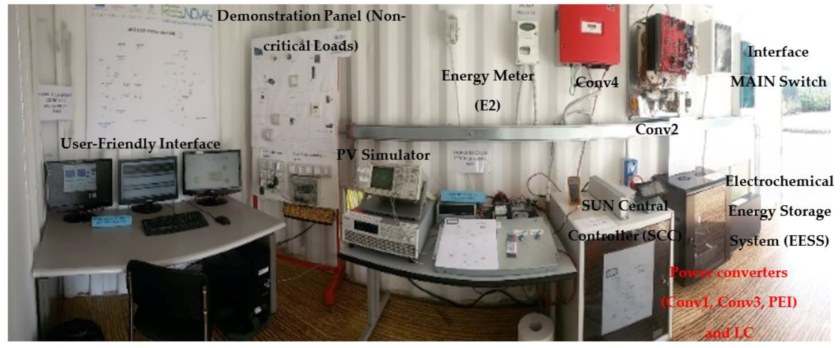
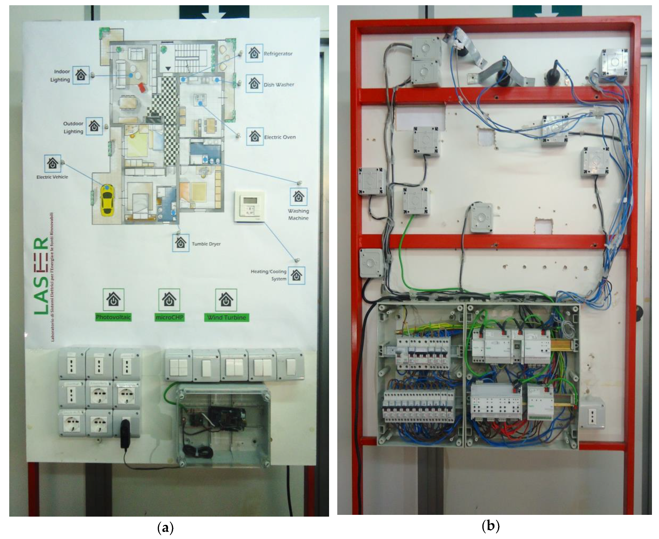
The SCC is equivalent to a microgrid central controller that performs the supervision and monitoring functions and the monitored data are displayed by a user-friendly interface (described in
Section 5).
The LC is equivalent to the micro-source, storage and load controllers. It implements a control strategy based on the concept of the distributed control strategy, the DBS control logic [
4,
7,
44,
45,
46,
47,
48,
49,
50,
51] as proposed by the authors in Reference [
4].
The SCC communicates the start-up of SUN and its shut-down, when it is requested by the user or in case of emergency, sending a logic control signal to the LCs.
A distributed control strategy is preferred because the system becomes independent of the central controller. Such a control strategy maintains the reliability inherent to the system structure by using the DC bus itself as a communication link, even in case of emergency.
Each power converter of micro-energy sources, storage systems and loads of the SUN is equipped with an LC. Within each LC a control logic and a transfer function that manages the source, storage or load according to the DBS control strategy is implemented. The communication among various LCs is based on the DC bus voltage level rather than an external communication link; the different micro-energy sources, storage systems and loads are effectively controlled using terminal quantities, as in case of decentralized control [
44,
45,
46,
47,
48,
49,
50,
51]. Therefore, the DBS control strategy allows the implementation of distributed control with the same reliability advantages as decentralized control. Through the use of the DBS control strategy, the power converters of the micro-energy sources, storage systems and loads can operate autonomously based only on the DC bus voltage level. Therefore, a voltage threshold is assigned to each converter.
The voltage threshold values are obtained with a ‘trial and error’ technique in the modeling and simulating phase, using the model presented by the authors in Reference [
4]. To each converter a voltage threshold is assigned, to trigger the point at which it begins charging or discharging. Each converter responds to the DC bus voltage level by their control logic implemented by the LC.
Based on DBS control strategy, the SUN converters respond to the DC bus voltage level, but at the same time change the DC bus voltage level, automatically controlling the other converters in the SUN. The DBS control logic is designed to maintain the power balance and the stable operation of the SUN system in any operating condition, in grid-connected and stand-alone configuration, as illustrated by the authors in References [
4,
7,
53].
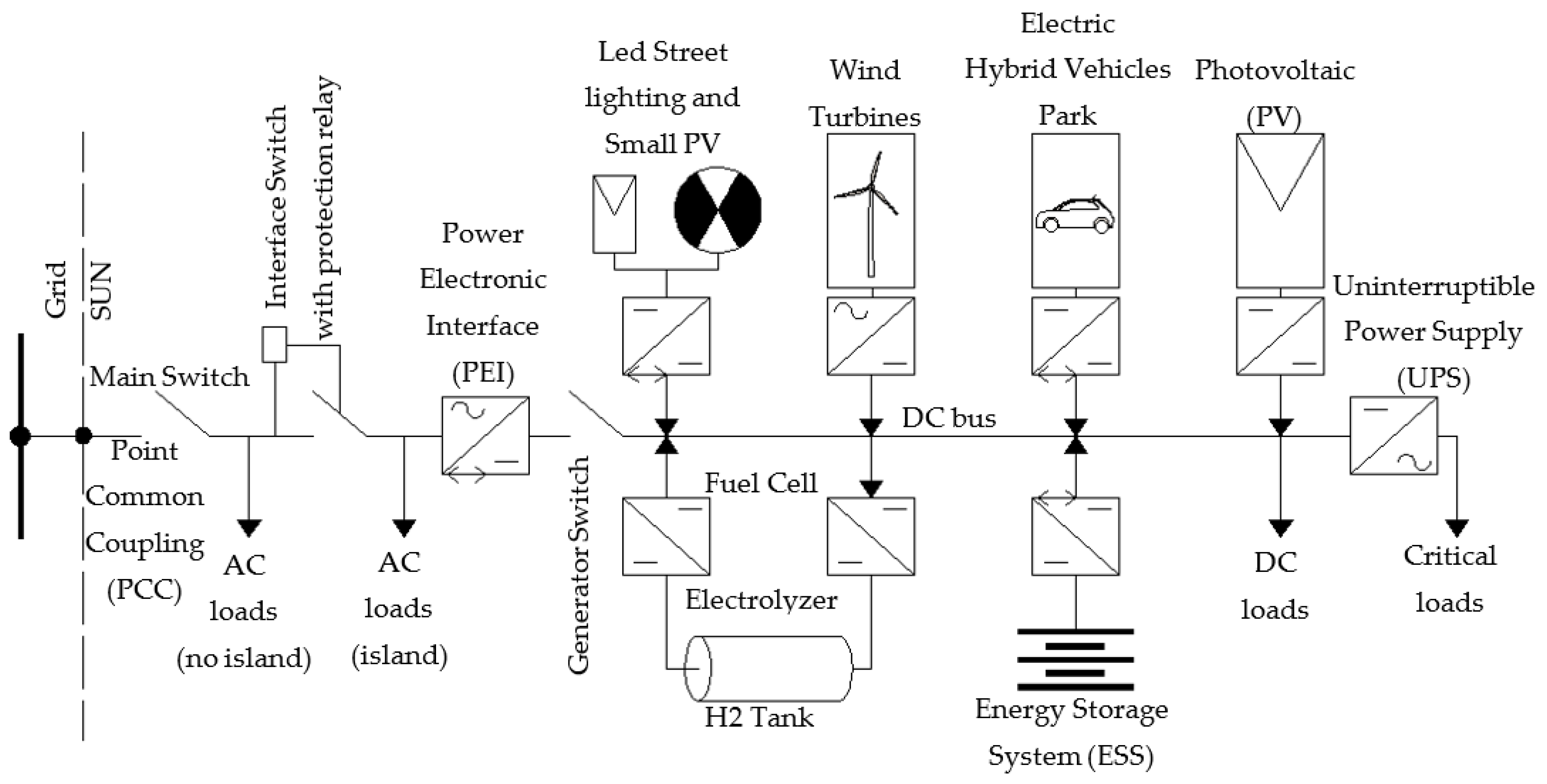
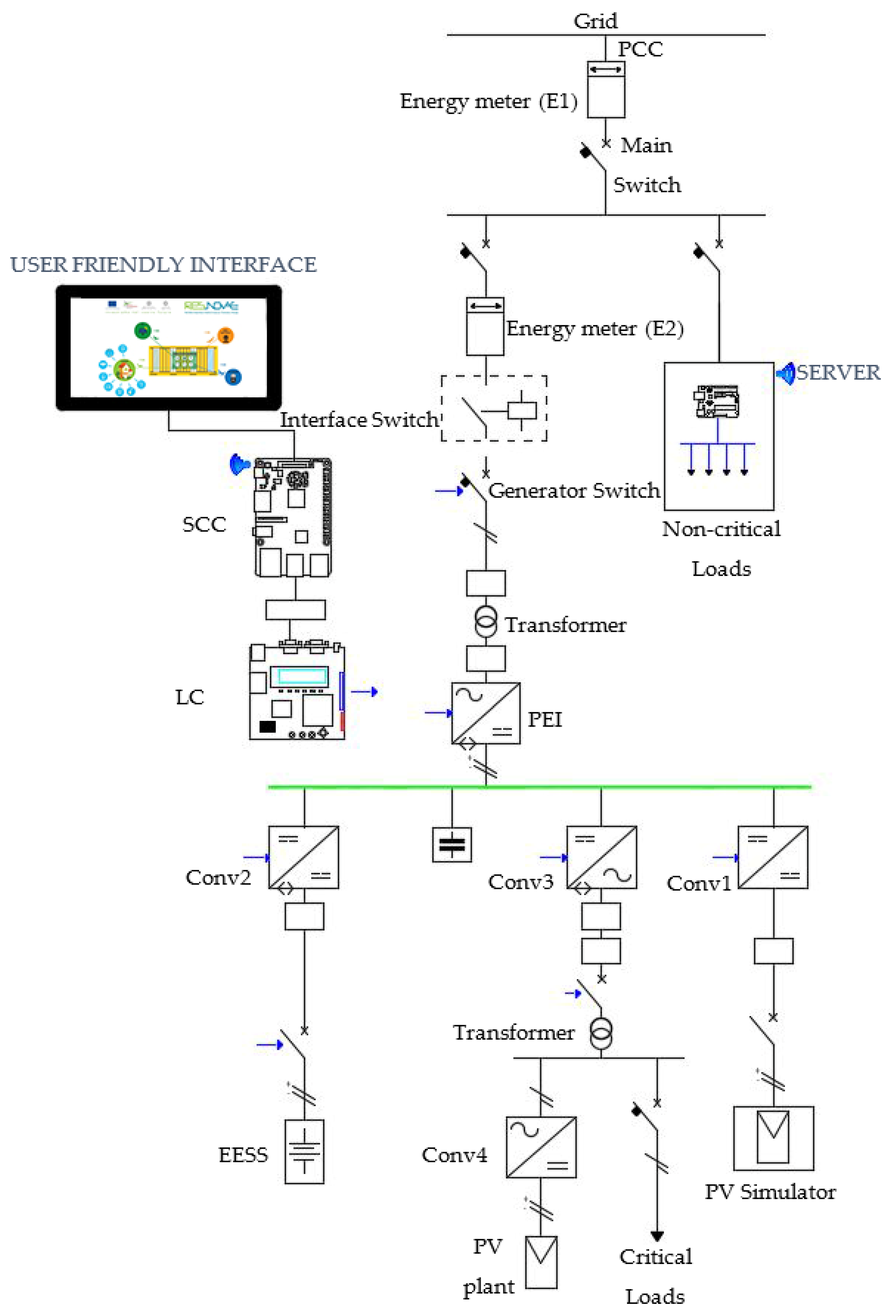
Therefore, while the PEI is the alone interface between the grid and a SUN (see
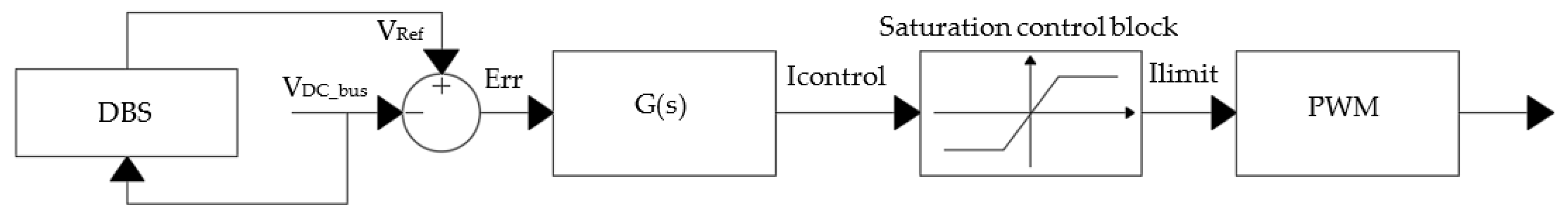
Figure 1), the other converters of SUN operate according to the DBS control strategy answering only to DC bus voltage level variations. The PEI converter can operate both as rectifier (absorbs power from the gird) and as an inverter (injects power into the grid), depending on the DC bus voltage (V
DC_bus) value. The goal of the PEI control is to regulate the power flow between SUN and grid, as illustrated by the control scheme of
Figure 2. The PEI converter operates based on DBS control logic tracking the properly DC bus voltage reference (V
DCref) when the SUN is in grid-connected configuration, otherwise the PEI tracking the AC voltage reference (V
ACref) when the SUN is in stand-alone configuration [
53]. The transfer function of the PEI control is G(s) that generate the Sinusoidal Pulse Width Modulation (SPWM) signals to drive the PEI converter.
Figure 3 shows the control scheme of the SUN LC; it is the same for each SUN converter; it includes the DBS control block in which the energy management strategy of the SUN is implemented; it determines the activation/deactivation of the converter and the switching from one type of control to another one (voltage/current, MPPT/V
Const, etc.), as described in the following. The first part of the control, using the measured value of V
DC_bus, evaluates the error (Err) respect to the voltage reference (V
Ref). The V
Ref is determined based on the implemented DBS control logic using V
DC_bus. The transfer function (G(s)) describes the behavior of the converter and determines the control current (I
control) of the converter, which is saturated to the value I
limit (by Saturation control block) if it exceeds the limit current of the source/storage system. Finally, the PWM block generates the signal control to drive the power converter.
In order to guarantee maximum continuity to the critical loads or with high priority, a control, which is also based on the DC bus voltage level, has been implemented. This control is enabled only in case of overload of the SUN to avoid the collapse of the SUN. Under these conditions the disconnection of the non-priority loads according to a priority table is envisaged (prioritized load shedding is performed). The disconnection of non-priority loads is progressive; each load is associated with a specific voltage level. The main difference between the disconnection of the load based on the DC bus voltage level and the DBS control logic is that, the latter uses the DC bus voltage level for dispatching the sources and storage systems, not for load shedding.
With DBS control strategy, the source and storage interface converters operate autonomously based on the DC bus voltage level. Each converter is assigned to a voltage threshold to trigger the point at which it begins charging or discharging.
It is worth to underline that each SUN has its own maximum regulating generation and storage capacity limited by the maximum total production capacity of the DG, the maximum storage capacity of all storage systems and the maximum critical and non-critical load power demand.
A principal power converter that regulates the DC bus voltage characterizing each operation mode, is defined in the following as Master Converter. All other power converters are defined as Slave Converters.
The switching among the different operation modes and the activation of the corresponding appropriate control logic for each power converter belonging to the SUN only depends on the measured DC bus voltage level.
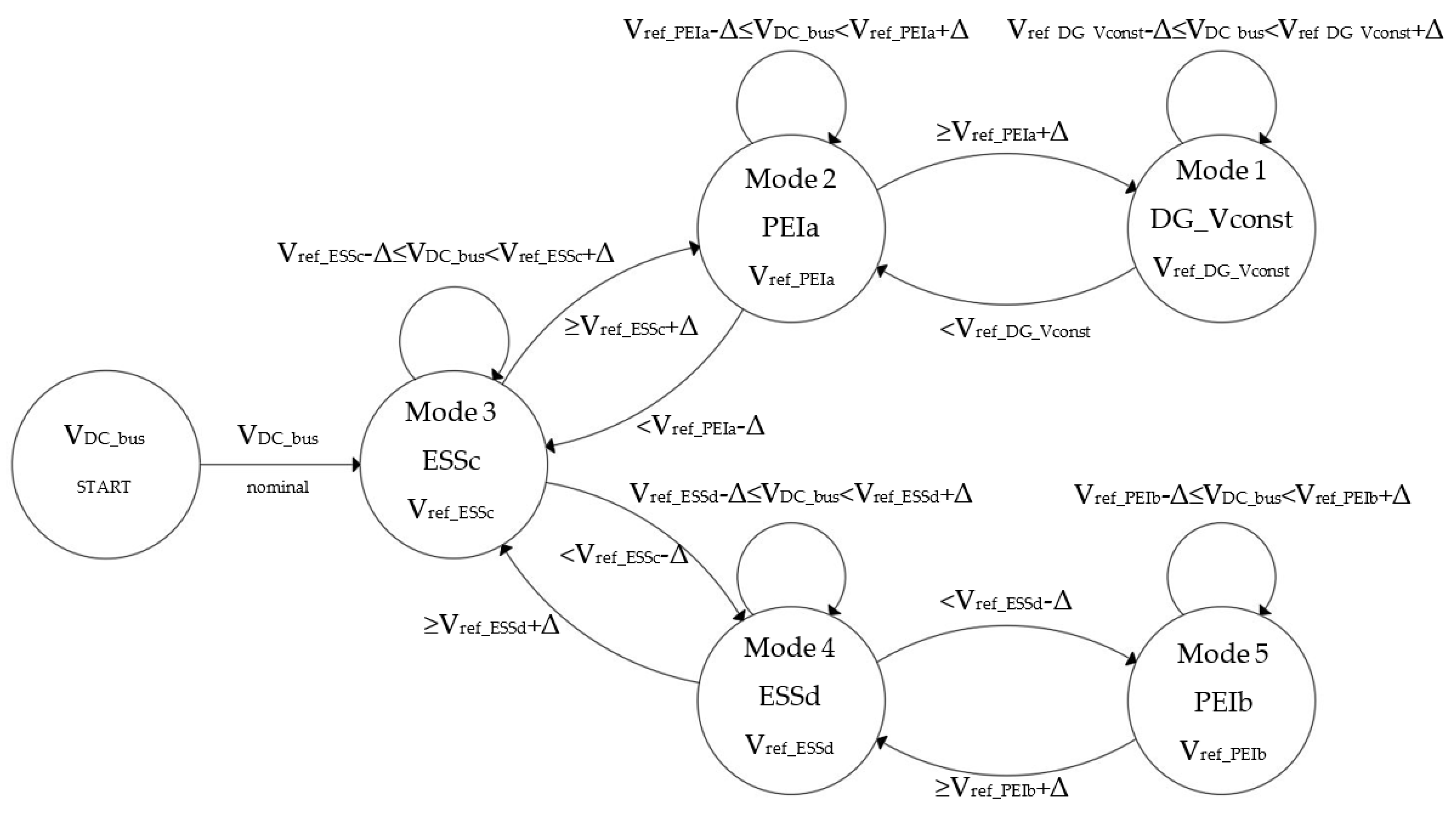
Figure 4 shows the possible operation modes of the SUN and the transitions between them.
The DC bus voltage level characterizing each possible operation mode of the SUN (V
ref_operation-modename) can vary respect to V
ref of ±Δ. Δ is the admissible variation between two consecutive DC bus voltage levels, evaluated by a trial and error technique and validate in the experimental setup testing, taking into account the following consideration: The differences between two DC bus values associated to two consecutive operation modes must be not excessively ‘small’ or ‘large’ [
10]. The Δ must not be small, since an improper change of the operating mode could be caused by the inaccuracies of the sampling system and/or by external disturbances, which may cause the DC bus to vary. Moreover, the Δ must not be large, since in this case the converters will operate in very different configurations, some with low voltage and high current, others with high voltage and low currents, this will result in low efficiency and possible failures for the converters. Considering the implementation procedure proposed in References [
4,
7,
53], each threshold has been verified also with the help of a DC load flow utilizing a prioritized fashion to maximize the use of RESs.
All operation modes of the SUN can be activated both in grid-connected or stand-alone configuration.
At this point, it is necessary to describe in details each operation mode (see
Figure 4), taking into account the sign conventions reported in
Table 1.
Mode 1—DG_Vconst: In this operation mode, the DG cannot operate at the Maximum Power Point (MPP), because the SUN has no possibility to inject power into the grid (stand-alone configuration). Therefore, the DG must operate at voltage constant in order to produce the power (P
DG) sufficient to supply the critical loads (P
Critical_loads), the non-critical loads (P
Loads, DC loads and AC loads island, see
Figure 1) and to charge the ESS (if SOC < 95%) at P
ESS_max_charge as reported in Equation (1).
Moreover, defining P
Δ as the difference among the DG power production at MPP (P
DG_MPP), the P
ESS_max_charge and the critical and non-critical loads power demand as reported in Equation (2):
The SUN can work in this operation mode when the PΔ is greater than zero and the SUN is disconnected by the grid. The DC bus voltage is equal to Vref_DG_Vconst and the master converter is the DG converter operating in voltage constant mode. When the microgrid is reconnected to the utility grid, the power surplus can be injected into the grid, then the VDC_bus decreases and the SUN switches to Mode 2—PEIa.
Mode 2—PEIa: The SUN works in this operation mode when the P
DG_MPP is greater than the sum of the power request by the critical and non-critical loads and of the P
ESS_max_charge (if SOC < 95%). Therefore, the P
Δ, defined in Equation (2), is positive, representing a power surplus that can be injected into the grid:
The PEI, acting as master converter, regulates the DC bus voltage to Vref_PEIa in inverter configuration. When the PΔ decrease less than zero, the VDC_bus decreases and the SUN switches to Mode 3–ESSc. Otherwise, when the grid is disconnected and the PΔ is positive, the VDC_bus increases and the SUN switches to Mode 1—DG_Vconst.
Mode 3—ESSc: The SUN works in this operation mode, when the P
DG_MPP is greater than the power absorbed by the critical and non-critical loads. The surplus is used to charge the ESS (P
ESS > 0 and SOC < 95%), but this surplus is less than P
ESS_max_charge. This means that:
Therefore, the PEI is deactivated and does not work in inverter or in rectifier configuration. In this case, the DC bus voltage is equal to Vref_ESSc and the master converter is the DC/DC ESS converter, with the highest DC bus charging voltage level. When the PESS in Equation (4) change sign, the VDC_bus decreases and the SUN switches to Mode 4–ESSd. In other words, the PESS becomes greater than zero and the ESS is discharging. Otherwise, when the PESS is greater than PESS_max_charge, the VDC_bus increases and the SUN switches to Mode 2—PEIa.
Mode 4—ESSd: The SUN works in this operation mode if the sum of P
DG_MPP and storage power P
ESS (P
ESS < 0) is sufficient to supply critical and non-critical loads power demand. The expression of P
ESS is the same of previously mode, reported in (4) but with P
ESS positive. In this condition, the SUN does not absorb power from the grid (P
Grid = 0) and the ESS is discharging (SOC > 40%). Therefore, the PEI does not work in inverter or in rectifier configuration. The ESS provide part of the energy demand. The DC/DC ESS converter, with the highest DC bus discharging voltage level, is the master converter regulating the DC bus voltage to V
ref_ESSd. When the power supplied by the ESS is greater than the maximum power allowed, the V
DC_bus decreases and the SUN switches to Mode 5—PEIb. In other words, the P
ESS should be greater than the P
ESS_max_discharge as reported in Equation (6):
Otherwise, when the power supplied by the ESS is less than zero, the VDC_bus increase and the SUN switches to Mode 3—ESSc. In other words, the PESS is lower than zero and the ESS is charging.
Mode 5—PEIb: The SUN works in this operation mode, if the sum of P
DG_MPP and P
ESS_max_discharge (greater than zero) is not sufficient to satisfy critical and non-critical loads power demand. Therefore, the grid absorbs the power deficit (P
Grid > 0), as indicated in Equation (7):
The PEI, acting as the master converter, regulates the DC bus voltage to Vref_PEIb in rectifier configuration. Otherwise, The VDC_bus increases and the SUN switches to Mode 4—ESSDischarge, if the power production by the DG increase or if the power demand by the loads decrease and the power absorbed by the grid decrease and becomes less than zero.
In order to clarify the implemented DBS control logic, the corresponding pseudocode that describes the behavior of each converter according to the above-mentioned operating modes is illustrated:
PEI Control:
IF (VDC_bus = Mode1 || Mode3 || Mode4)
PEI OFF;
ELSE IF (VDC_bus = Mode2)
PEI injects power into the grid;
ELSE IF (VDC_bus = Mode5)
PEI absorbs power from the grid;
DC/DC PV Control:
IF (VDC_bus = Mode1)
DC/DC PV controls the DC bus to Vref_DG_Vconst (no MPPT);
ELSE IF (VDC_bus = Mode2 || Mode3 || Mode4 || Mode5)
DC/DC PV works in MPPT;
DC/DC ESS Control:
IF (VDC_bus = Mode1 || Mode2)
ESS is in charging at maximum power;
ELSE IF (VDC_bus = Mode3)
DC/DC ESS control DC bus at Vref_ESS_Charge;
ELSE IF (VDC_bus = Mode4)
DC/DC ESS control DC bus at Vref_ESS_Discharge;
ELSE IF (VDC_bus = Mode5)
ESS is in discharging at maximum power;
DC/AC Conv3 Control:
IF (VDC_bus > black-start voltage value)
DC/AC Conv3 ON;
ELSE
DC/AC Conv3 OFF;
6. The Experimental Results
In
Table 3 the values of DC bus voltage thresholds are reported. The DC bus voltage threshold characterizing each possible operation mode of the SUN can vary respect to the nominal DC bus voltage (V
ref) of ±Δ [
4,
53,
56].
In
Table 3, the first voltage threshold value equal to 280 V corresponds to the start-up procedure when the SUN must operate in grid-connected configuration: The PEI charges the DC bus operating as a rectifier. Until the PEI not increases the DC bus voltage to the value of 350 V all LCs of the other converters are not enabled. After that, the DC Bus voltage reaches the value of 350 V and so all LCs are enabled and the DBS starts.
In the case of SUN in stand-alone configuration, the DC bus is charged by the EESS and the corresponding voltage threshold value is equal to 370 V. The master converter is the half-bridge DC/DC converter (Conv2). In this case, all LCs are instantaneously enabled when the DC bus voltage reaches the value of 370 V.
The DC bus voltage threshold of 410 V corresponds to the case of PEI operating as master converter to inject an energy surplus into the grid (the PEI is operating as inverter), instead when the PEI operating as master converter to absorb the energy deficit need to supply the critical loads by grid (the PEI is operating as rectifier) the DC bus voltage threshold is 390 V.
The last DC bus voltage threshold of 430 V corresponds to the case in which the PV DC/DC converter must operate not in MPPT but in constant voltage mode. The PV cannot operate at the MPP, because the SUN has no possibility to inject power into the grid (stand-alone configuration or a specified grid request).
It is worth to underline that in case of a SOC greater than the maximum value (95%), the EESS cannot be charged and so the PV production surplus must be injected into the grid. In case in which this surplus cannot be injected into the grid (case of stand-alone configuration or a specified grid request), then the DC bus voltage increases and so the PV boost DC-DC converter (Conv1) operates as master converter in constant voltage (no MPPT) [
4].
In the following, the most significant experimental results are reported.
In the
Figure 11,
Figure 12,
Figure 13,
Figure 14 and
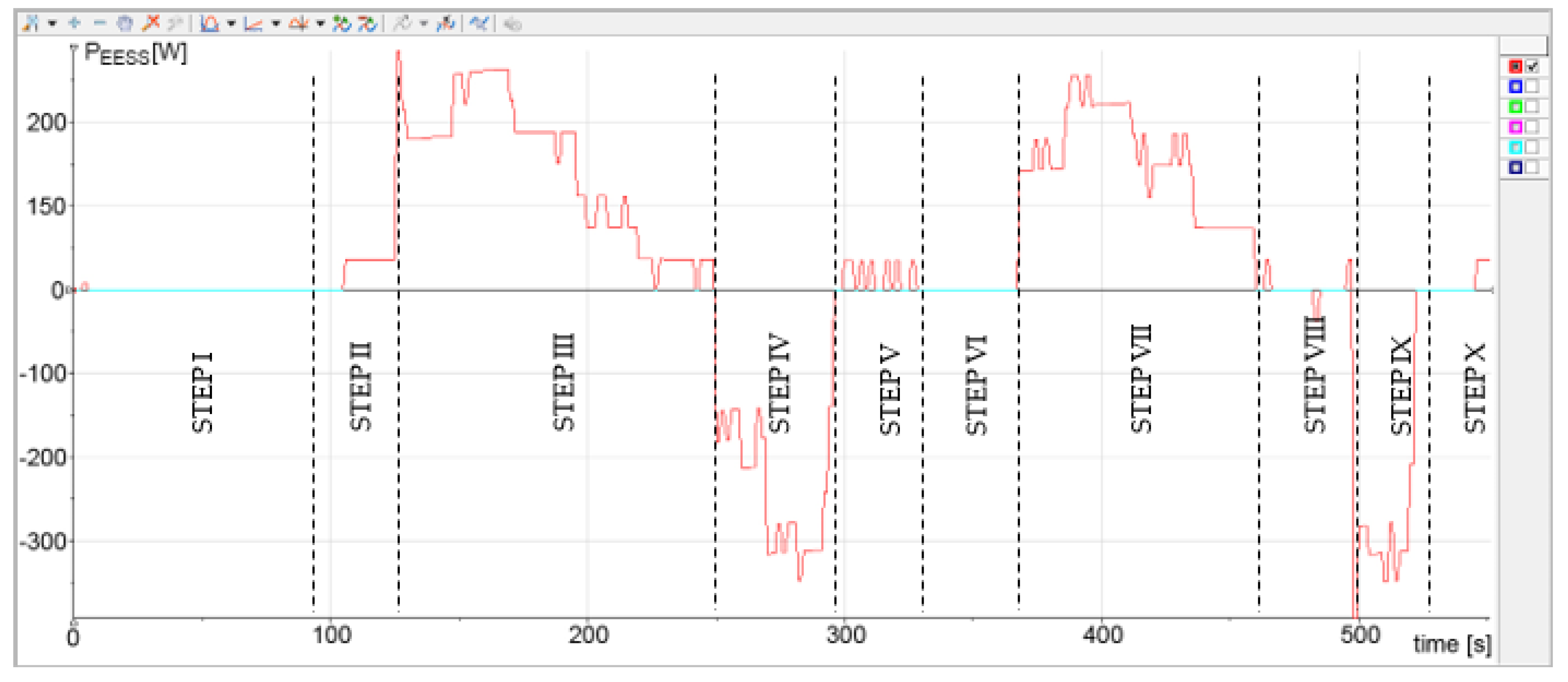
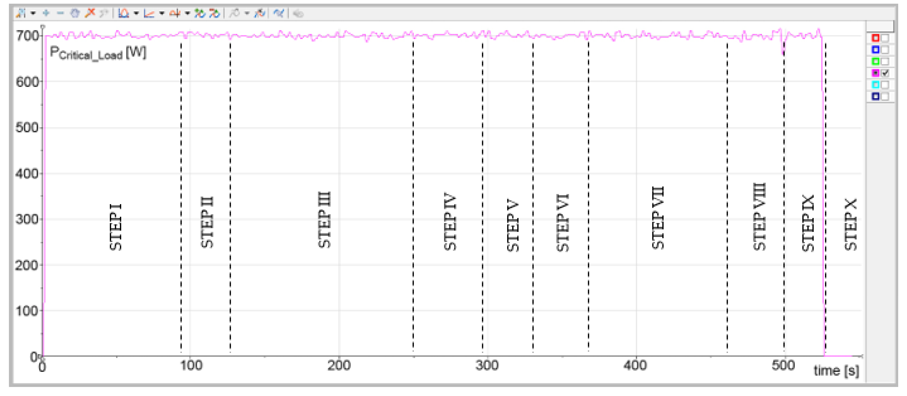
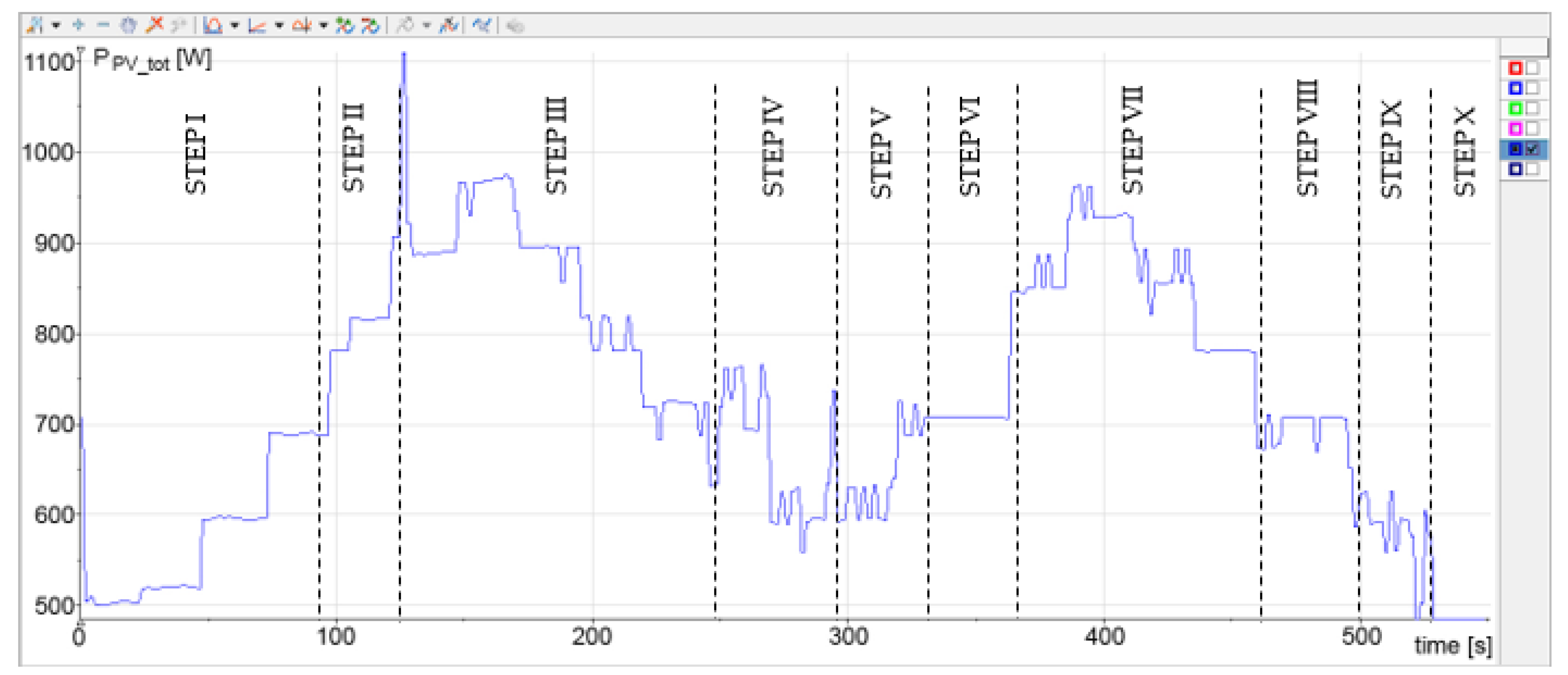
Figure 15 are reported the results in terms of power: The power exchanged from the EESS with the SUN (in
Figure 11), the power absorbed from the critical loads (in
Figure 12), the power production by the PV plant summed to the power production of the PV simulator (in
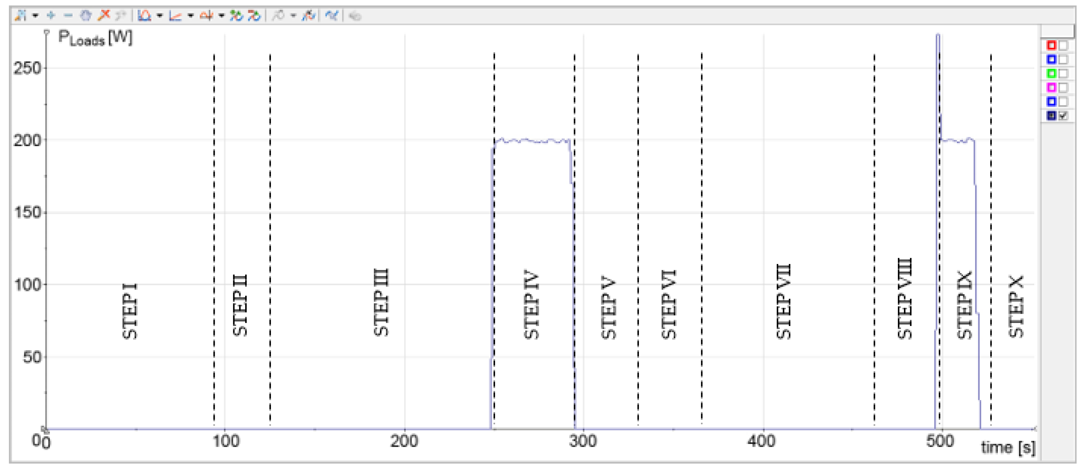
Figure 13), the power absorbed from the non-critical loads (in
Figure 14) and the power exchanged between the SUN and the grid by the PEI (in
Figure 15).
The experimental time-interval is 550 s. In this time-interval the PV production is constant and about 500 W from the PV plant, plus a variable PV production from the PV simulator connected to the DC bus through the Conv1 (
Figure 5 and
Figure 6).
The power absorbed by critical loads is about 700 W (
Figure 12); while non-critical loads absorb a total power about 200 W (
Figure 14).
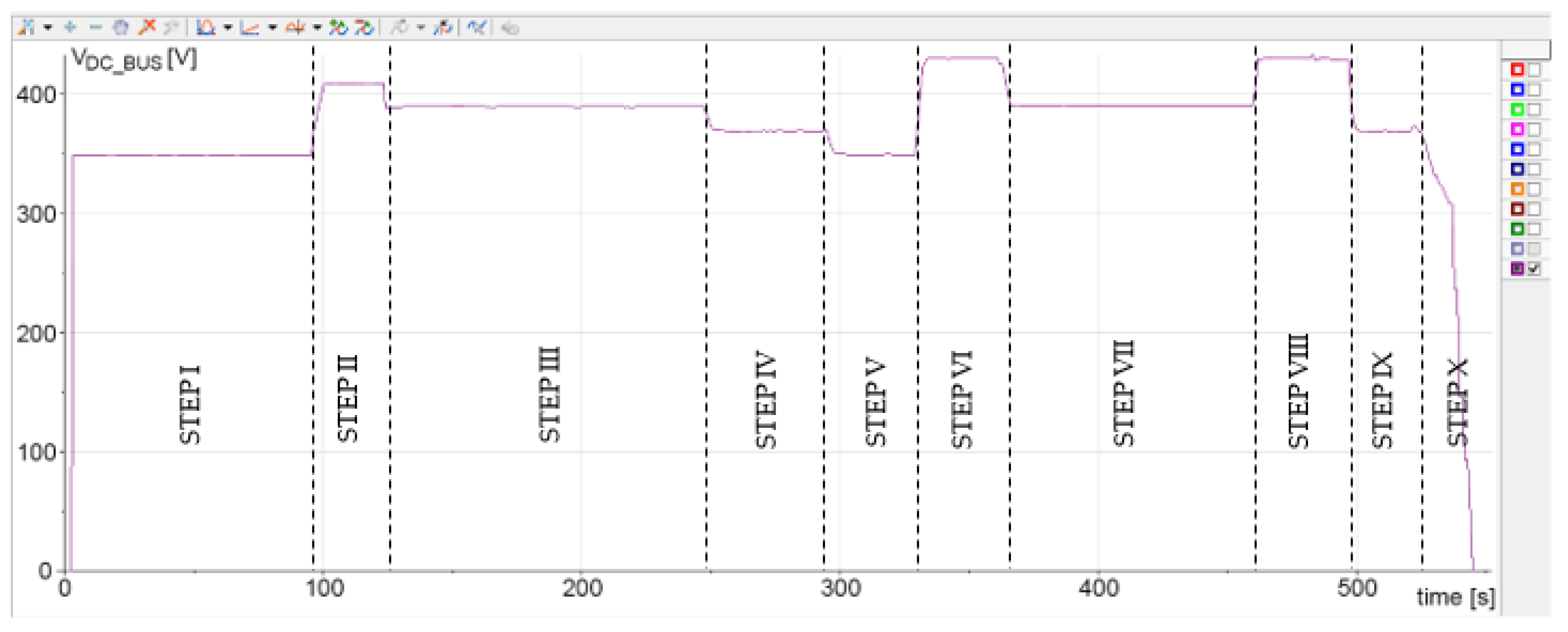
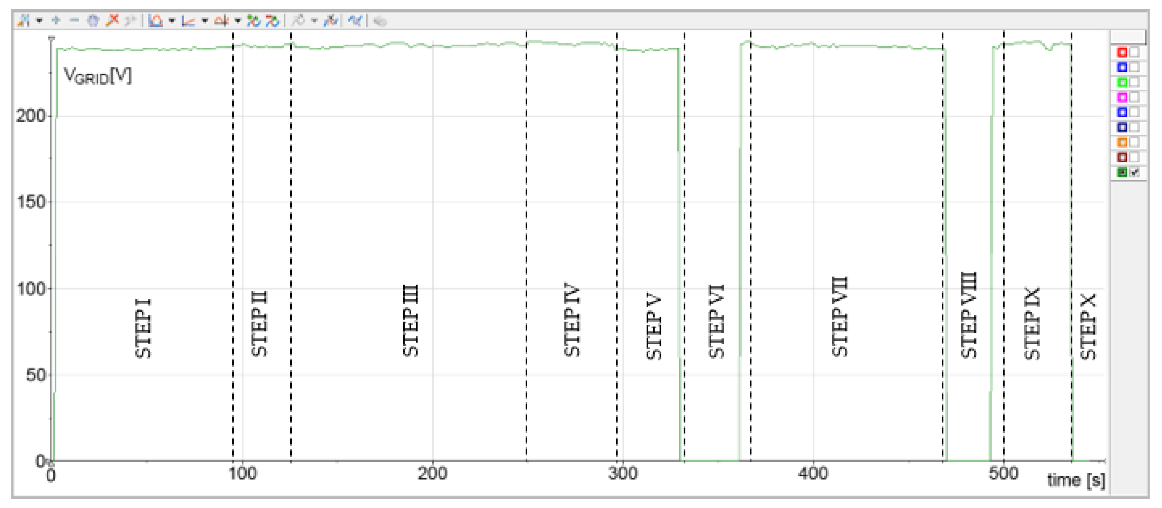
Observing the DC bus voltage profile, it is possible to individuate the different step of the experimental test, as described in the following.
STEP I (0–90 s): The EESS is disconnected from the SUN; the SUN starts and the PEI regulates the DC bus voltage to the reference voltage of 350 V (Mode 5,
Figure 8); the PEI absorbs from the grid the power deficit needed to supply the critical loads of the SUN. The power absorbed from the grid gradually decreases (
Figure 15), while the PV power production increases (
Figure 13).
STEP II (90–125 s): The EESS is yet disconnected; the PV power production increases and become greater than the power absorbed from the critical loads (
Figure 12 and
Figure 13), then the PV power surplus is injected into the grid (
Figure 15). The voltage of the DC bus increases at 410 V (Mode 2,
Figure 8).
STEP III (125–250 s): The EESS is connected to the SUN; all the PV power surplus is used to charge the EESS (
Figure 11), then P
Grid becomes zero (
Figure 15); the DC bus voltage decreases to 390 V (Mode 3,
Figure 8). Therefore, when the PV power increases (
Figure 13), the power absorbed by the EESS increases, while when the PV power production decreases, the power absorbed by the EESS decreases. In this step the power exchanged between the SUN and the grid is zero, because the EESS is able to absorb all PV power surplus.
STEP IV (250–290 s): The demonstration panel, simulating any loads, requires a power of 200 W, the PV power production is not sufficient to satisfy this power request, therefore the EESS begins to discharge (
Figure 11). The DC bus goes down to 370 V (Mode 4,
Figure 8). The PEI supplies at the AC side the power of 200 W to satisfy the power request of the demonstration panel (
Figure 6 and
Figure 15).
It is worth to underline that in the next steps V and VI, the EESS is disconnected from the SUN, in order to test the operation modes Mode 5 and 3.
STEP V (290–335 s): The EESS is disconnected; the demonstration panel power request is zero; the PV power production (
Figure 13) is less than the power absorbed by critical loads (
Figure 12), therefore the power deficit is supplied by the grid (
Figure 15). The DC bus decreases until to 350 V (Mode 5,
Figure 8).
STEP VI (335–365 s): A grid blackout occurs (
Figure 10), the DC bus voltage increases to 430 V (Mode 3,
Figure 8); being the PV power production (
Figure 13) greater than the power absorbed from the critical loads (
Figure 12), the Conv1 (
Figure 6) has to work in voltage constant mode.
STEP VII (365–465 s): The EESS is reconnected to the SUN; the PV power production increases (
Figure 13) and the PV power surplus is used priority to charge the EESS (
Figure 11); moreover, although the grid is resumed working (
Figure 10), the power exchanged with the grid is zero (
Figure 15), because the EESS is able to absorb all PV power surplus. The DC bus voltage decreases to 390 V (Mode 3,
Figure 8).
STEP VIII (465–495 s): A new grid blackout occurs (
Figure 10); the EESS is fully charged (SOC > 95%), therefore the PV power surplus cannot be used to charge the EESS, then the DC bus voltage increases to 430 V (Mode 1,
Figure 8); the PV power production is limited by the Conv1 (
Figure 6 and
Figure 13) to satisfy the power loads demand and limit the increase of the DC bus voltage.
STEP IX (495–520 s): The grid is resumed working (
Figure 10); the demonstration panel sends to the PEI a power request of 200 W (
Figure 14); the PV power production is less than the total loads demand (
Figure 13), then power deficit is supplied by the EESS (
Figure 11). The DC bus voltage decreases to 370 V (Mode 4,
Figure 8).
STEP X (520–550 s): The SUN is shutdown, therefore all voltages and power progressively decrease to zero.
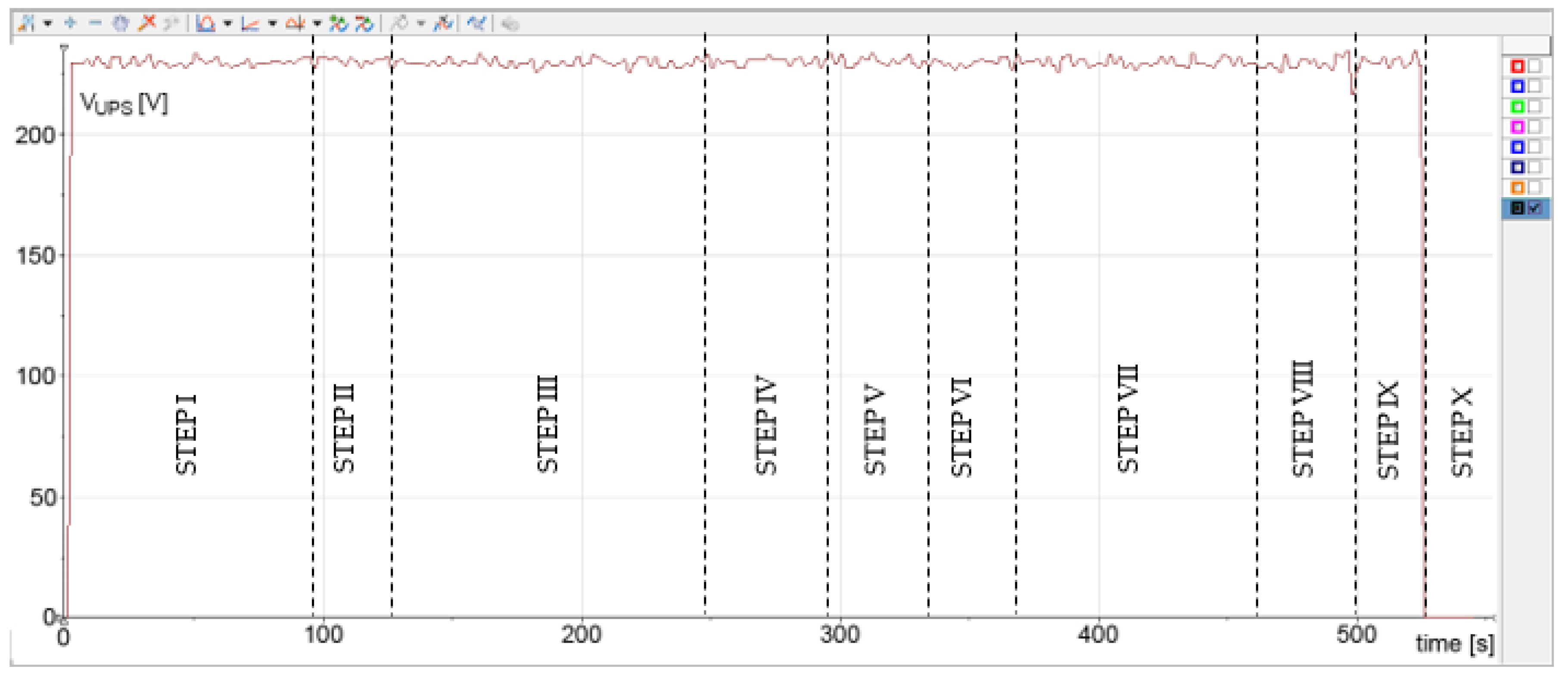
It worth to underline that in all experimental steps, the voltage of critical loads (
Figure 9) is guaranteed at 230 V, 50 Hz by the Conv3 (
Figure 6).

 ,
, 


