Insulation Coordination of Arcing Horns on HVDC Electrode Lines: Protection Performance Evaluation, Influence Factors and Improvement Method


Abstract
:1. Introduction
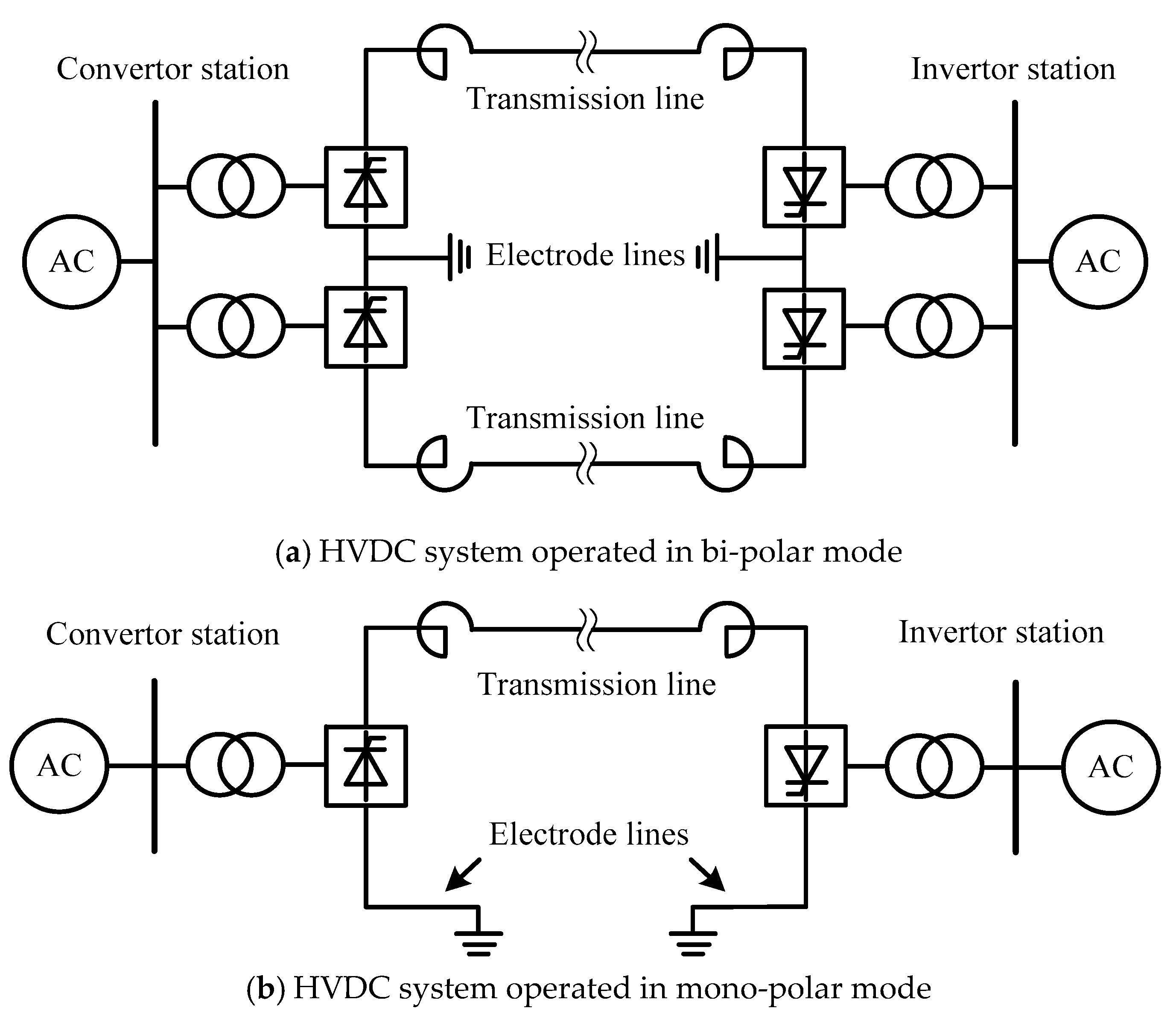
1.1. Insulation Coordination Problem of Arcing Horns on HVDC Electrode Lines
1.2. Current Reaserches on Insulation Coordination of Arcing Horns on HVDC Electrode Lines
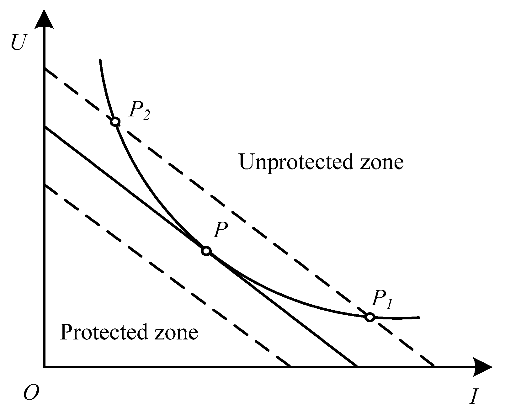
1.3. Static Stability Criterion of Fault Arc on HVDC System (U-I Characteristic Method)
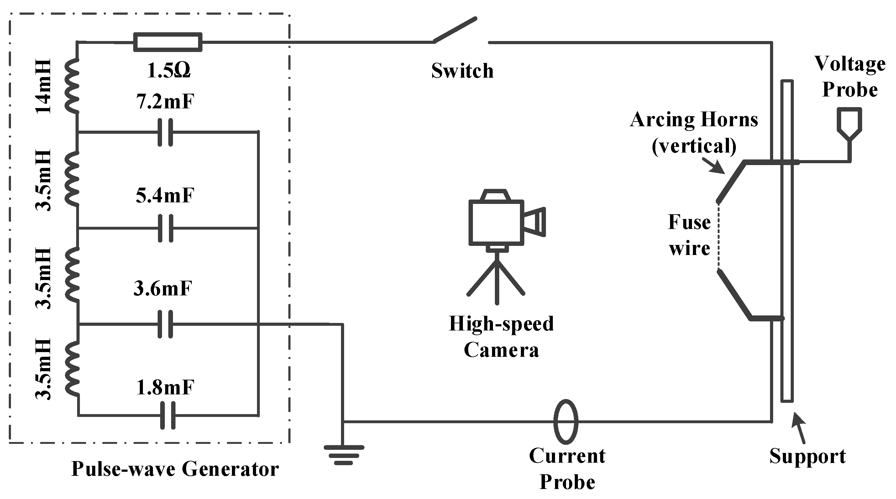
2. Experimental Settings
3. Behaviors and Characteristics of Long Free Burning Arc
3.1. Behaviors of Long Free Burning Arc
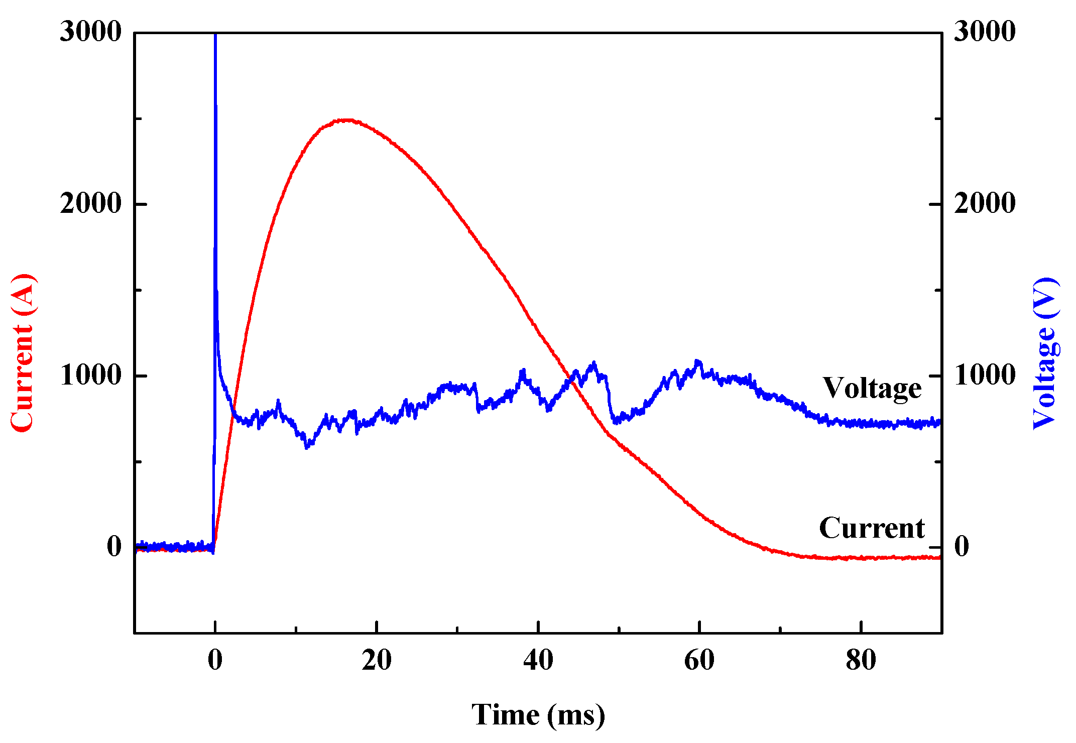
3.1.1. Typical Waveforms
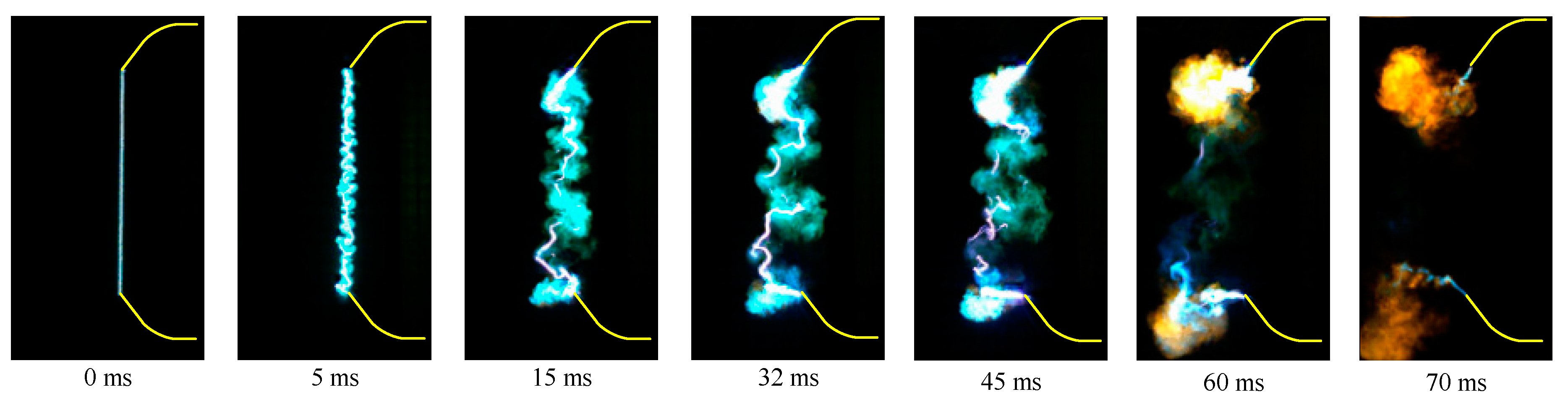
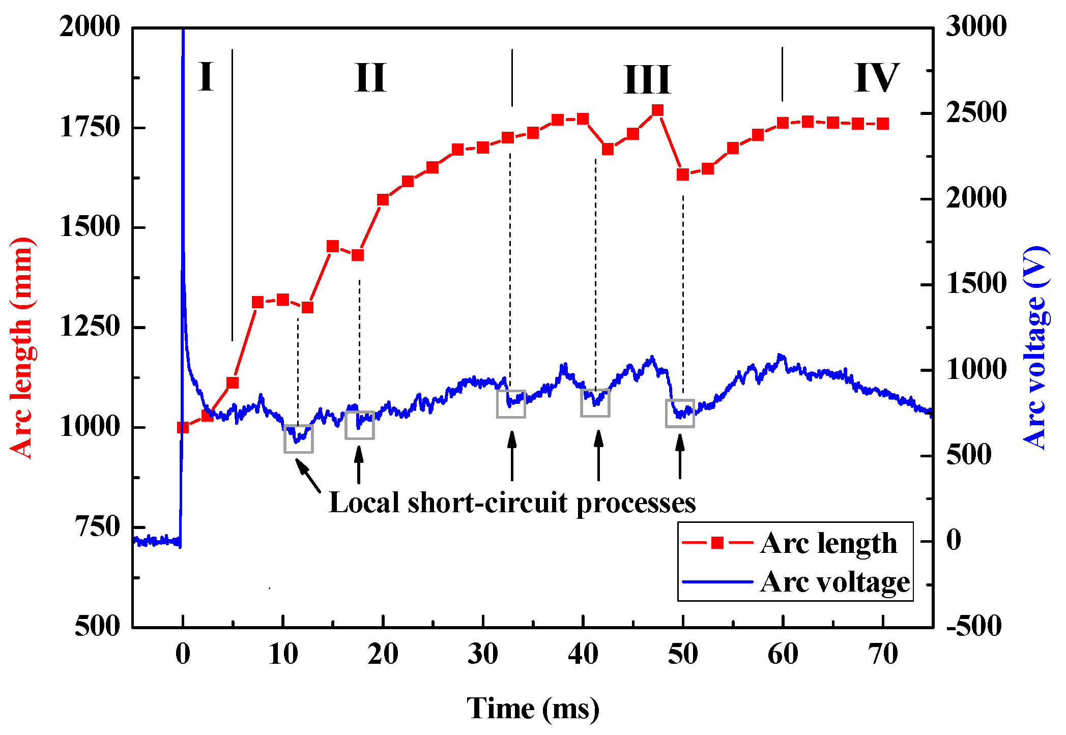
3.1.2. Development Process of a Long Free Burning Arc
- Phase I (0.1–3 ms): This phase is called the slow expansion phase. The arc motion is gentle, the arc expansion speed is slow and the arc column is stable with a clear shape.
- Phase II (3–32 ms): This phase is called the fast expansion phase. The arc motion is violent, the arc expansion speed is fast, and the arc column is relative stable. It can be seen that there are blurs around the arc column making the shape of arc column unclear. The blurs are conductive, which will induce the local short circuit processes of arc columns.
- Phase III (32–60 ms): This phase is called the violent motion phase. The arc motion becomes more violent, however, the arc expansion slows down. The blurs around the arc column are diffused which leads frequent local short circuit processes making the arc column unstable and without a clear shape.
- Phase IV (60–70 ms): This phase is called the extinction phase, in which both the arc motion and expansion cease, and the arc is quenched to its final extinction.
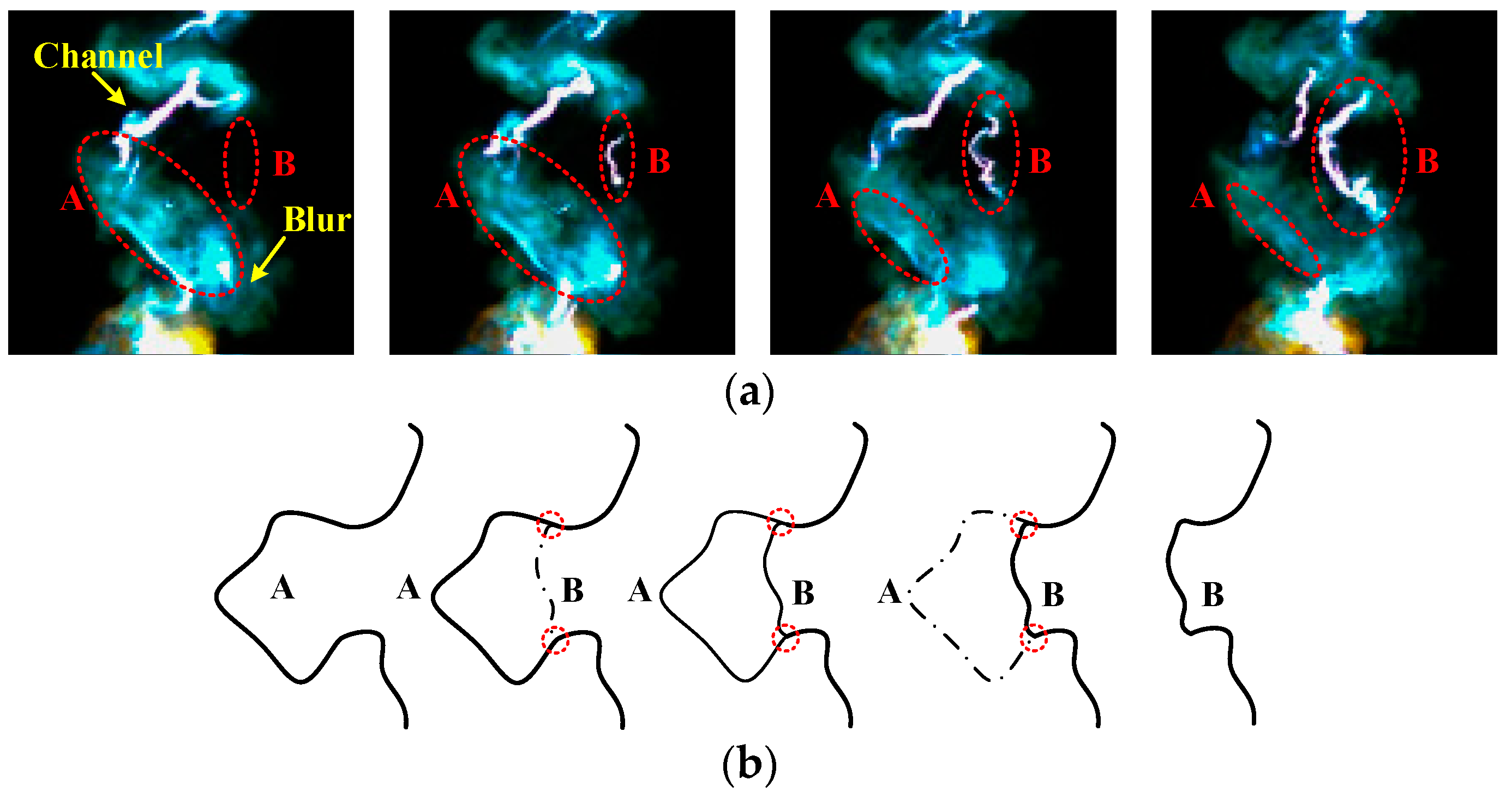
3.1.3. Instability of Long Free Burning Arc
3.2. Electric Characteristic of Long Free Burning Arcs
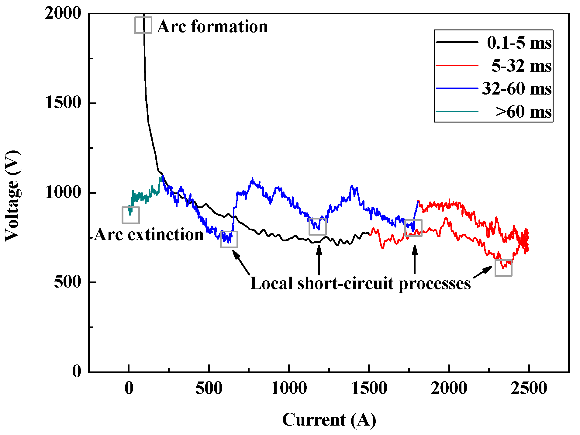
3.2.1. U-I Characteristic of Long Free Burning Arc
- Phase I (0.1–3 ms): In this phase, the arc current Iarc rises but the arc voltage Uarc falls off quickly. The U-I characteristic curve Uarc(Iarc) approximately obeys a negative power function law.
- Phase II (3–32 ms): In this phase, the arc current remains at a high level, and on the other hand, the arc voltage shows a slight uptrend with vibrations caused by the local short circuit processes.
- Phase III (32–60 ms): In this phase, the arc current decreases continuously, the arc voltage vibrations are more violent and frequent, which implies frequent local short circuit processes.
- Phase IV (60–70 ms): In this phase, the arc goes into the extinction state, and both the arc current and voltage are decreasing.
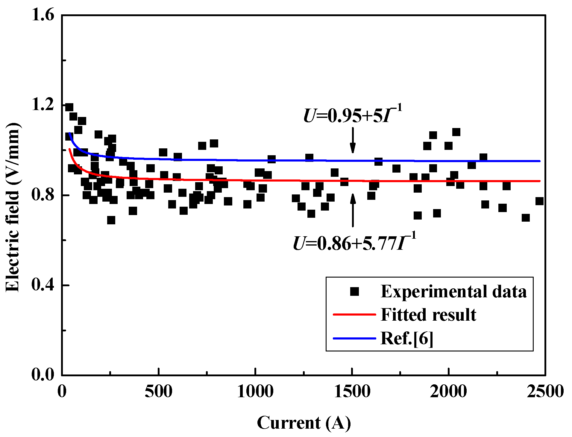
3.2.2. E-I Characteristic of Long Free Burning Arc
4. Insulation Coordination of Arcing Horns on HVDC Electrode Lines
4.1. U-I Characteristic of HVDC Electrode Lines and Fault Arc
4.1.1. U-I Characteristic of HVDC Electrode Lines
4.1.2. U-I Characteristic of Fault Arc
4.2. Protection Region of Arcing Horns
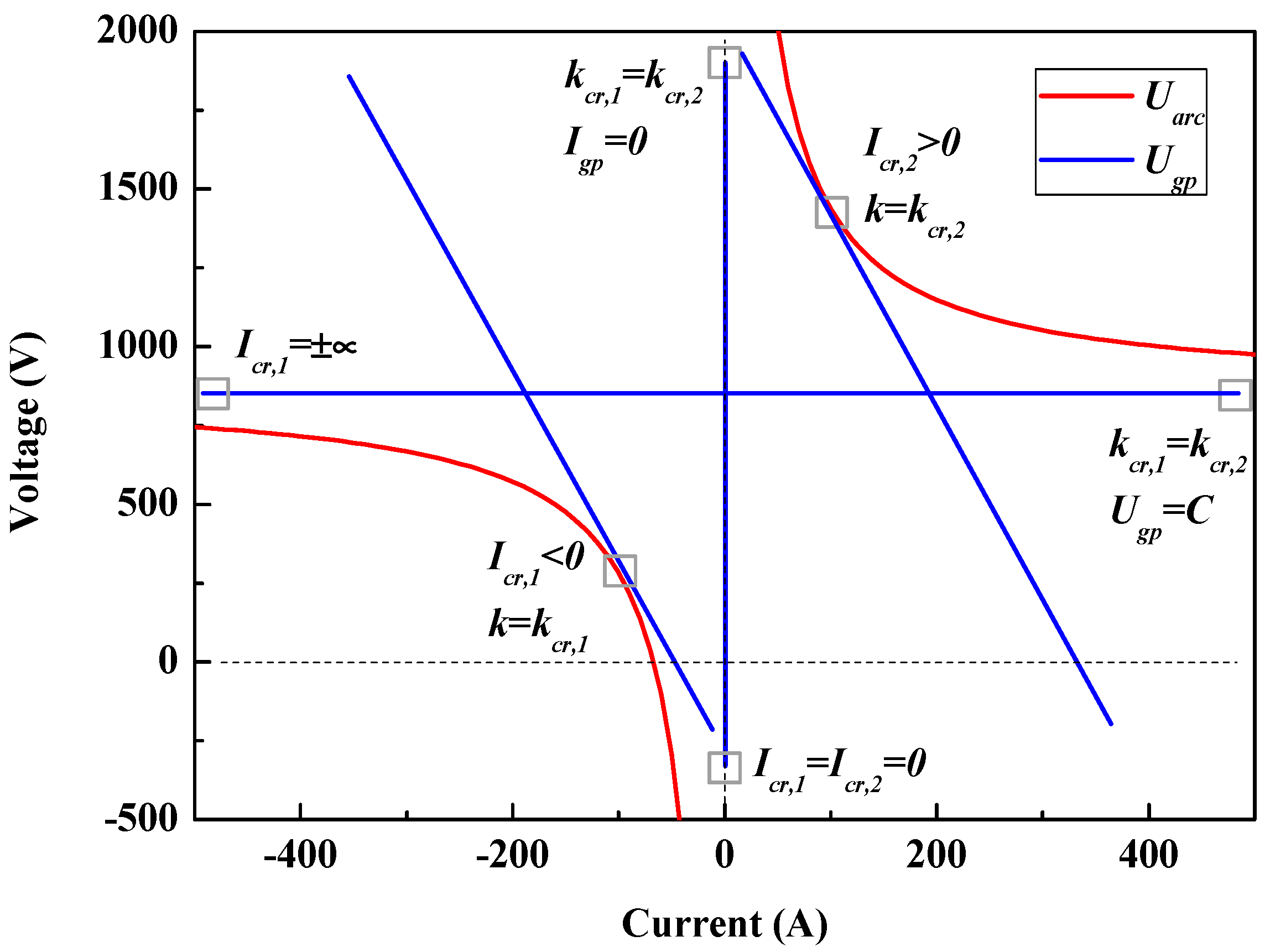
4.2.1. Solutions of State Equation
4.2.2. Protection Region of Arcing Horns
5. Influence Factors on Protection Performance of Arcing Horns
5.1. Analysis Method of Influence Factors Based on Power Balance
5.1.1. Relations between Power Balance, Protection Performance and U-I Characteristics
5.1.2. Influence of Circuit Parameters on U-I Characteristics
5.2. Variation of Protection Performance of Arcing Horns with Circuit Parameters
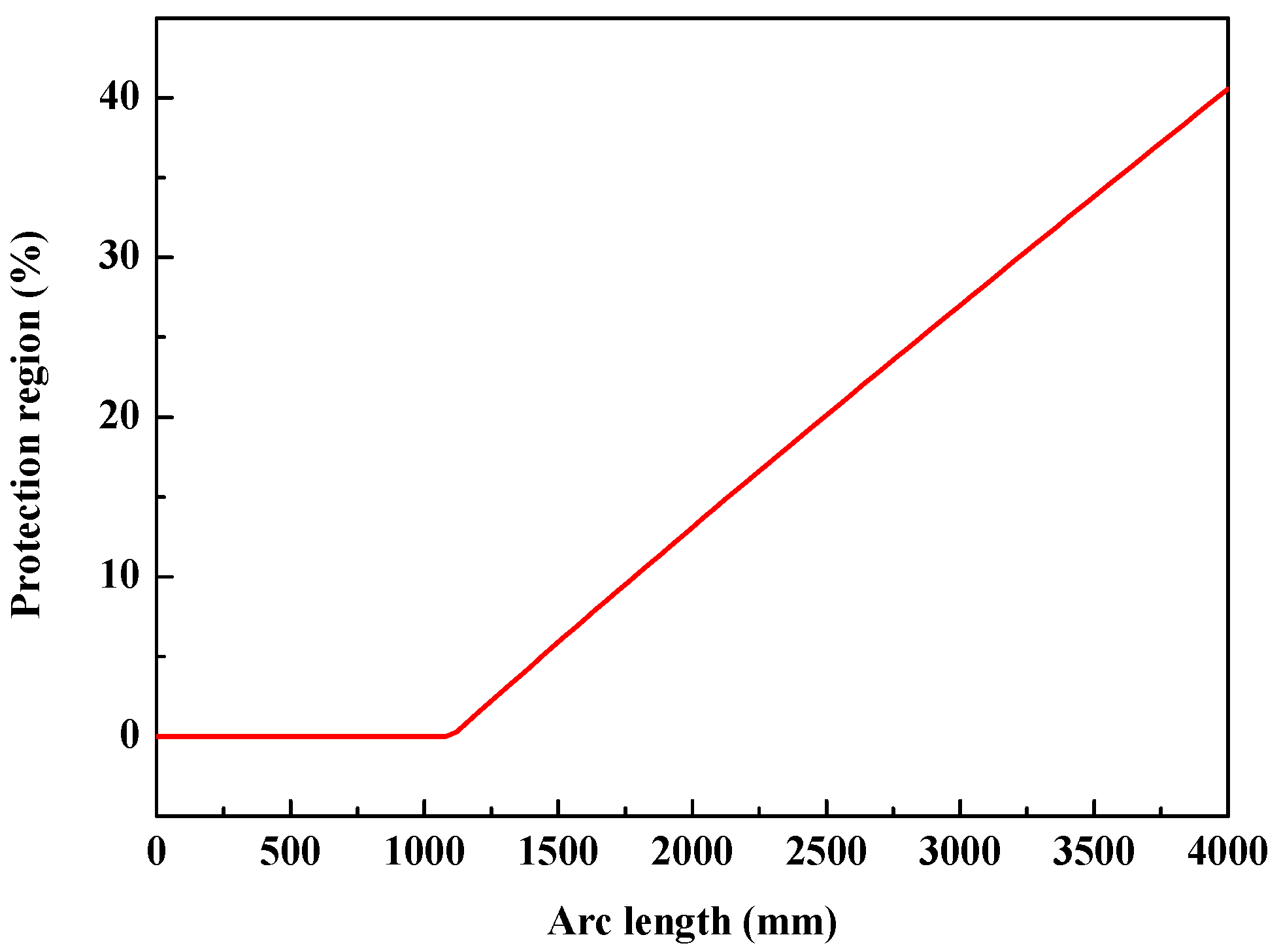
5.2.1. Arc Length
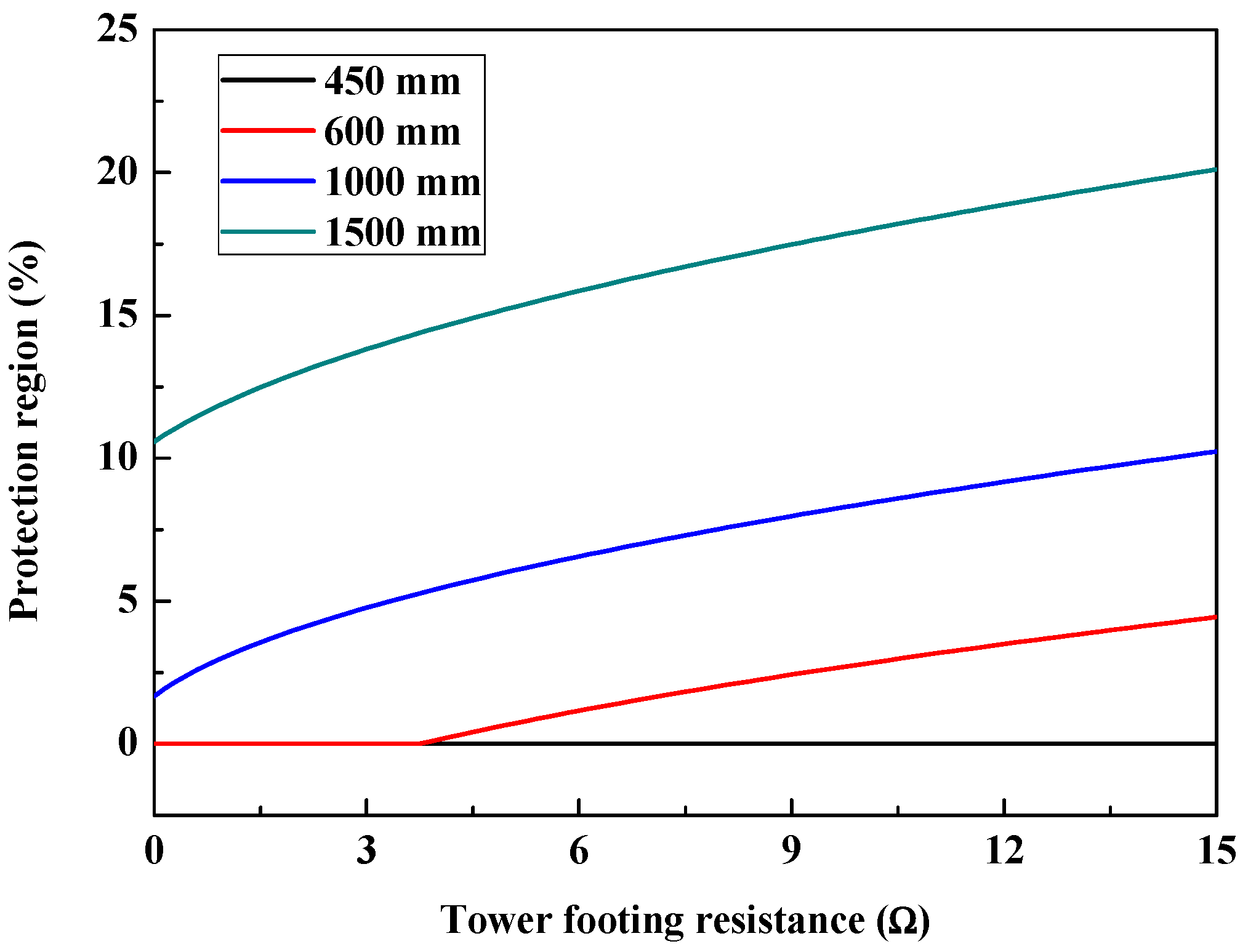
5.2.2. Tower Footing Resistance
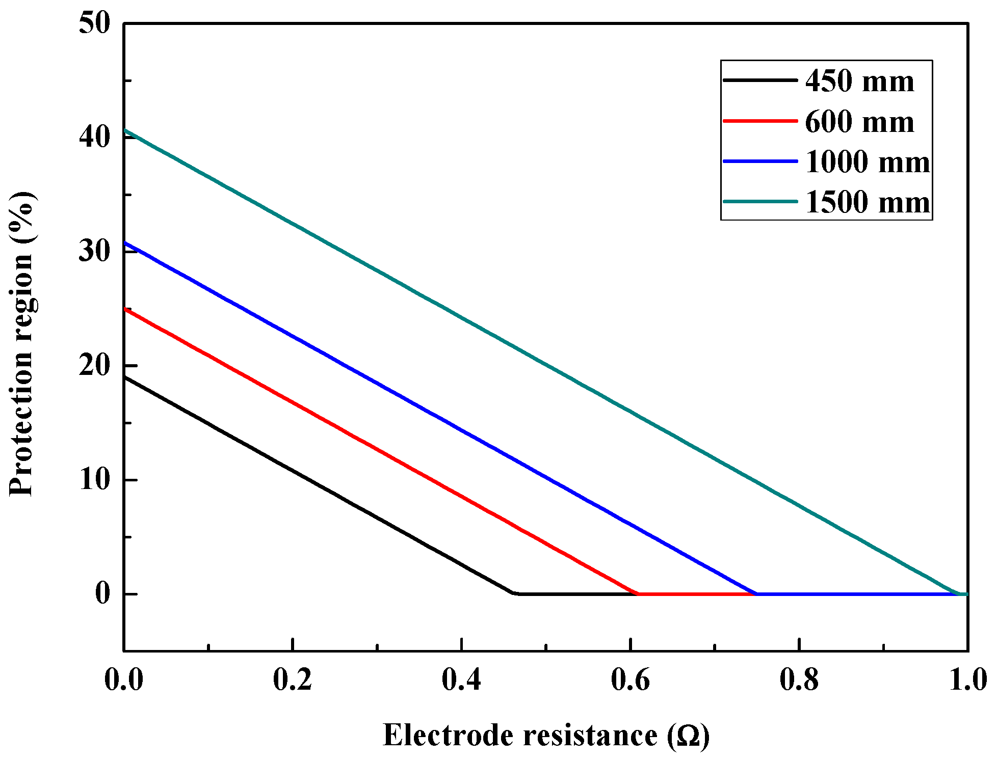
5.2.3. Electrode Resistance
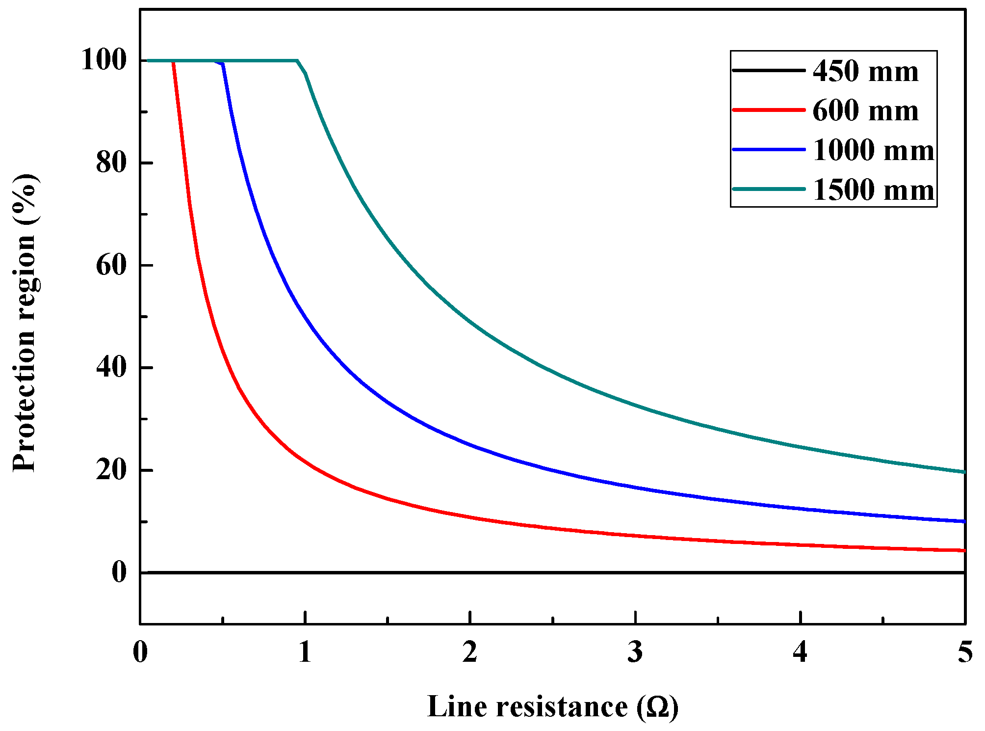
5.2.4. Line Resistance
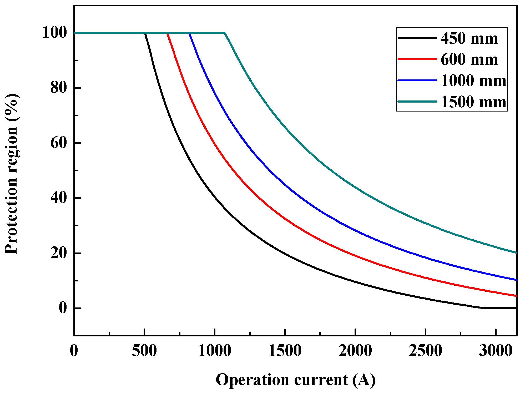
5.2.5. Operation Current
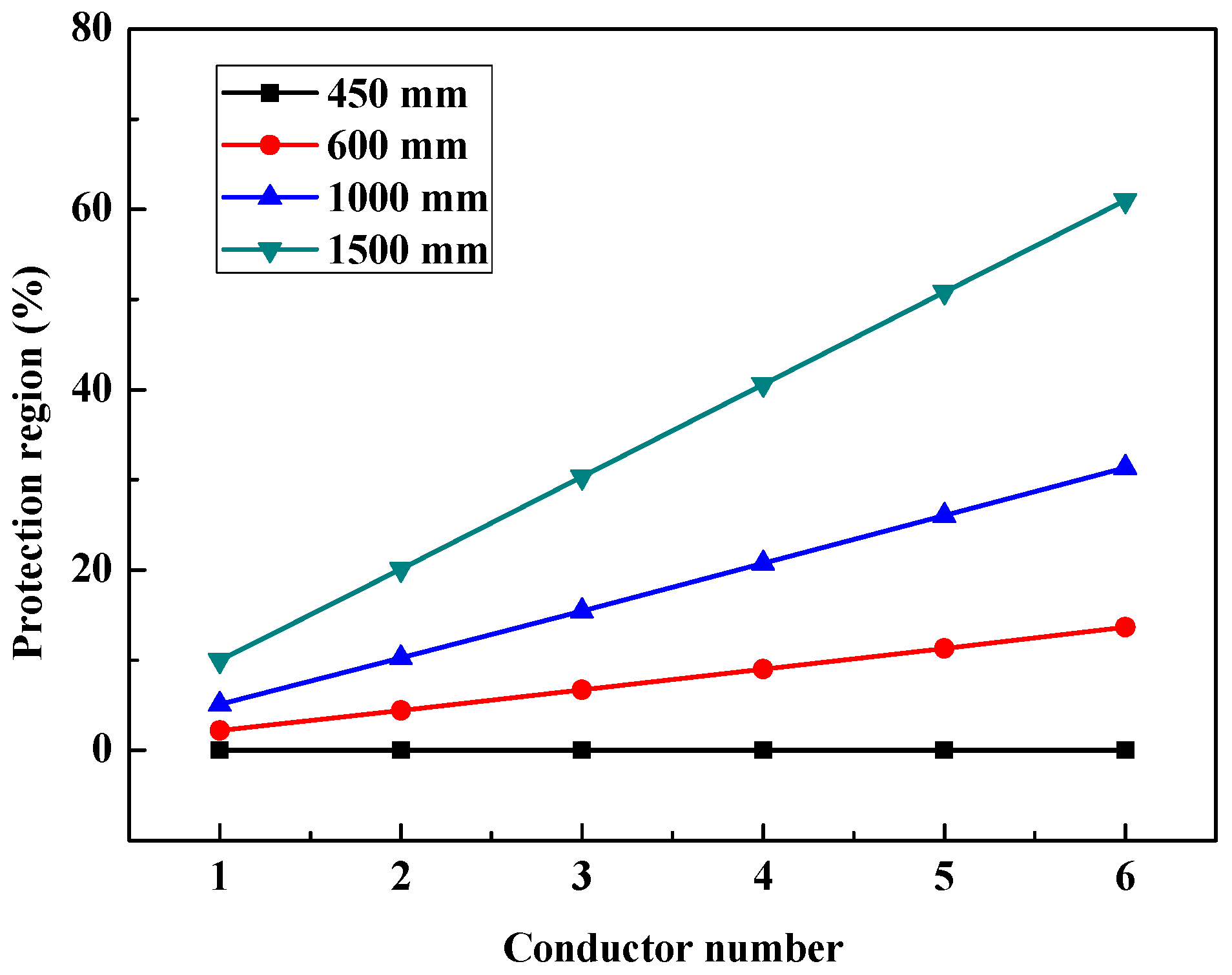
5.2.6. Conductor Number
5.3. Analysis on Influence Factors Based on Approximation Solution of State Equation
5.3.1. Approximation Solution of State Equation
5.3.2. Analysis on Influence of Circuit Parameters Based on Approximation Solutions
6. Protection Performance Improvement Methods for Arcing Horns
6.1. Protection Performance Improvement by Adjusting Circuit Parameters
6.2. Protection Performance Improvement by Diffirential Arcing Horns Configuration Strategy
7. Conclusions
- (1)
- The development process of long free burning arcs can be divided into slow expansion, fast expansion, violent motion and extinction phases. The long free burning arc column is very unstable and made up of segments of short channels and conductive blurs. The local short circuit is thought to be the main cause of the instability of arc column.
- (2)
- The arcing horns are only suitable for the HVDC electrode lines systems of low operation current and short distance. For the HVDC electrode lines systems of high operation current and long distance, the protection performance of arcing horns is limited, and additional auxiliary devices for arc extinction are needed to realize full protection.
- (3)
- The effect ways for the protection performance improvement of arcing horns are increasing the arc voltage and tower footing resistance, and reducing the total resistance of HDVC electrode line system. Differential arcing horns configuration strategy is recommended for cost saving.
Acknowledgments
Author Contributions
Conflicts of Interest
References
- Gu, S.Q.; He, J.L.; Zeng, R.; Zhang, B.; Xu, G.Z.; Chen, W.J. Motion characteristics of long ac arcs in atmospheric air. Appl. Phys. Lett. 2007, 90, 051501. [Google Scholar] [CrossRef]
- Li, Q.M.; Cong, H.X.; Sun, Q.Q.; Xing, J.Y.; Chen, Q. Characteristics of Secondary AC Arc Column Motion Near Power Transmission Line Insulator String. IEEE Trans. Power Deliv. 2014, 29, 2324–2331. [Google Scholar] [CrossRef]
- Sima, W.X.; Tan, W.; Yang, Q.; Luo, B.; Luo, L. Experimental research on power frequency arc movement process of 110 kV composite insulators in rod shape parallel gap lightning protection devices. Proc. CSEE 2011, 32, 114–121. [Google Scholar]
- Kinya, S.; Inaba, T. Electric and moving characteristics of dc kilo-ampere high current arcs in atmospheric air. Electr. Eng. Jpn. 1990, 110, 9–20. [Google Scholar]
- Stokes, A.D.; Oppenlander, W.T. Electric arcs in open air. J. Phys. D Appl. Phys. 1991, 24, 26–35. [Google Scholar] [CrossRef]
- Goda, Y.; Iwata, M.; Ikeda, K.; Tanaka, S. Arc voltage characteristics of high current fault arcs in long gaps. IEEE Trans. Power Deliv. 2000, 15, 791–795. [Google Scholar] [CrossRef]
- Terzija, V.; Preston, G.; Popov, M.; Terzija, N. New static “airarc” EMTP model of long arc in free air. IEEE Trans. Power Deliv. 2011, 26, 1344–1353. [Google Scholar] [CrossRef]
- Strachan, D.C. High-current, steel-cathode, free-burning arcs. J. Phys. D Appl. Phys. 1977, 10, 361–370. [Google Scholar] [CrossRef]
- Sölver, C.E. Electric Arcs and Arc Interruption. Chalmers University of Technology, Götenburg, Sweden, EEK 195 High Voltage Technology, Lecture. Available online: http://193.140.122.139/high_voltage/elkraft/www.elkraft.chalmers.se/GU/EEK195/lectures/Lecture7.pdf (accessed on 17 January 2018).
- Paukert, J. The arc voltage and the resistance of LV fault arcs. In Proceedings of the 7th International Symposium on Switching Arc Phenomena, Łódź, Poland, 27 September–11 October 1993; pp. 49–51. [Google Scholar]
- Ammerman, R.F.; Gammon, T.; Sen, P.K.; Nelson, J.P. DC-arc models and incident-energy calculations. IEEE Trans. Ind. Appl. 2010, 46, 1810–1819. [Google Scholar] [CrossRef]
- Canellas, J.; Clarke, C.D.; Portela, C.M. DC Arc Extinction on Long Electrode Lines for HVDC Transmission. In Proceedings of the International Conference on DC Power Transmission (ICDCPT), Montreal, QC, Canada, 4–8 June 1984; pp. 127–133. [Google Scholar]
- Jankov, V.; Stobart, M. HVDC system performance with a neutral conductor. In Proceedings of the 2010 International Conference on High Voltage Engineering and Application (ICHVE), New Orleans, LA, USA, 11–14 October 2010; pp. 188–191. [Google Scholar]
- Li, X.D.; Li, H.; Liu, Y.; Lin, F.C.; Xu, Z.J. Experimental study on insulation coordination of arcing horns on HVDC electrode lines. In Proceedings of the 19th International Symposium on High Voltage Engineering, Pilsen, Czech, 23–28 August 2015. [Google Scholar]
- Ohtaka, T.; Iwata, M.; Tanaka, S.; Goda, Y. Development of an EMTP simulation model of arcing horns interrupting fault current. IEEE Trans. Power Deliv. 2010, 25, 2017–2024. [Google Scholar] [CrossRef]
- Wang, J.F.; Liu, J.L.; Wu, G.Q.; Liu, Q.; Guo, W. Research and application of jet stream arc-quenching lightning protection gap (JSALPG) for transmission lines. IEEE Trans. Dielectr. Electr. Insul. 2015, 22, 782–788. [Google Scholar] [CrossRef]
- Wang, J.F.; Wu, D. Development of an arc-extinguishing lightning protection gap for 35 kV overhead power lines. IET Gener. Transm. Distrib. 2017, 11, 2897–2901. [Google Scholar] [CrossRef]


| Gap Distance (mm) | Average Stable Arc Length (mm) | |
|---|---|---|
| Vertical Gap | Horizontal Gap | |
| 450 | 1083 | 1142 |
| 600 | 1313 | 1384 |
| 1000 | 1762 | 1705 |
| 1500 | 2454 | 2512 |
| Rt (Ω) | Protection Region (%) | |||
|---|---|---|---|---|
| 450 mm | 600 mm | 1000 mm | 1500 mm | |
| 3 | 0 | 0 | 4.8 | 13.8 |
| 6 | 0 | 0 | 5.3 | 14.4 |
| 9 | 0 | 0.7 | 6.0 | 15.2 |
| 12 | 0 | 1.8 | 7.3 | 16.7 |
| 15 | 0 | 4.4 | 10.2 | 20.1 |
| Re (Ω) | Protection Region (%) | |||
|---|---|---|---|---|
| 450 mm | 600 mm | 1000 mm | 1500 mm | |
| 0.1 | 14.9 | 20.9 | 26.7 | 36.6 |
| 0.2 | 13.9 | 19.9 | 25.7 | 35.5 |
| 0.3 | 12.2 | 18.2 | 24.0 | 33.8 |
| 0.4 | 8.8 | 14.7 | 20.5 | 30.4 |
| 0.5 | 0 | 4.4 | 10.2 | 20.1 |
| Rl (Ω) | Protection Region (%) | |||
|---|---|---|---|---|
| 450 mm | 600 mm | 1000 mm | 1500 mm | |
| 0.977 | 0 | 22.2 | 51.0 | 99.8 |
| 1.954 | 0 | 17.7 | 40.8 | 80.0 |
| 2.931 | 0 | 13.3 | 30.7 | 60.1 |
| 3.908 | 0 | 8.9 | 20.5 | 40.1 |
| 4.885 | 0 | 4.4 | 10.2 | 20.1 |
| Idc (A) | Protection Region (%) | |||
|---|---|---|---|---|
| 450 mm | 600 mm | 1000 mm | 1500 mm | |
| 630 | 77.1 | 100.0 | 100.0 | 100.0 |
| 1260 | 57.3 | 81.6 | 100.0 | 100.0 |
| 1890 | 37.5 | 55.8 | 73.4 | 100.0 |
| 2520 | 17.8 | 29.9 | 41.7 | 61.6 |
| 3150 | 0 | 4.4 | 10.2 | 20.1 |
| n | Protection Region (%) | |||
|---|---|---|---|---|
| 450 mm | 600 mm | 1000 mm | 1500 mm | |
| 1 | 0 | 2.2 | 5.1 | 10.0 |
| 2 | 0 | 4.4 | 10.2 | 20.1 |
| 3 | 0 | 6.7 | 15.5 | 30.3 |
| 4 | 0 | 9.0 | 20.7 | 40.6 |
| 5 | 0 | 11.3 | 26.0 | 50.8 |
| 6 | 0 | 13.6 | 31.4 | 61.0 |
© 2018 by the authors. Licensee MDPI, Basel, Switzerland. This article is an open access article distributed under the terms and conditions of the Creative Commons Attribution (CC BY) license (http://creativecommons.org/licenses/by/4.0/).
Share and Cite
Li, X.; Li, H.; Liu, Y.; Lin, F. Insulation Coordination of Arcing Horns on HVDC Electrode Lines: Protection Performance Evaluation, Influence Factors and Improvement Method. Energies 2018, 11, 430. https://doi.org/10.3390/en11020430
Li X, Li H, Liu Y, Lin F. Insulation Coordination of Arcing Horns on HVDC Electrode Lines: Protection Performance Evaluation, Influence Factors and Improvement Method. Energies. 2018; 11(2):430. https://doi.org/10.3390/en11020430
Chicago/Turabian StyleLi, Xiandong, Hua Li, Yi Liu, and Fuchang Lin. 2018. "Insulation Coordination of Arcing Horns on HVDC Electrode Lines: Protection Performance Evaluation, Influence Factors and Improvement Method" Energies 11, no. 2: 430. https://doi.org/10.3390/en11020430