Thermodynamic Performance of Heat Exchangers in a Free Piston Stirling Engine


Abstract
:1. Introduction
2. Methodology
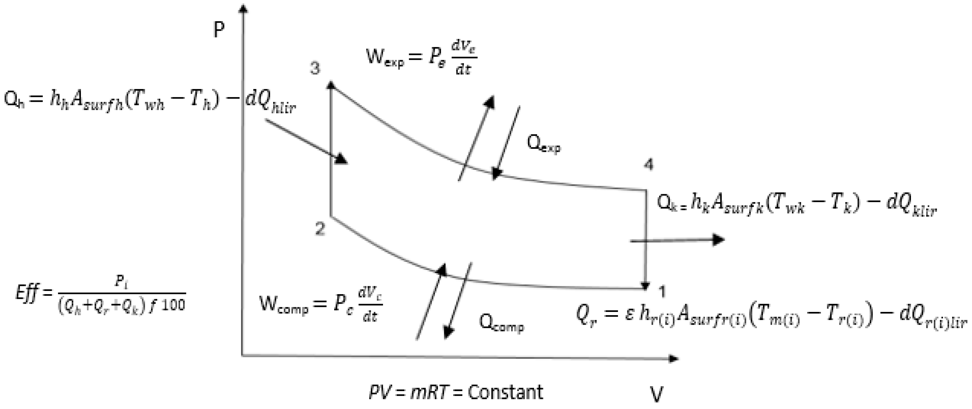
2.1. Thermodynamic Cycle of the Stirling Engine
- Isothermal compression (1–2): At the first stage of the cycle, there is compression of the working fluid between the moving elements (piston and displacer) by their oscillatory movements.
- Isochoric heating (2–3): The working fluid flows via the heat exchangers and there is heat transfer from the regenerator to the working fluid as the temperature increases.
- Isothermal expansion (3–4): At this stage, the working fluid exerts pressure on the displacer during the expansion in the hot space.
- Isochoric cooling (4–1): In the last stage of the cycle, there is heat transfer from the working fluid to the regenerator as it moves back via the heat exchanger.
2.2. Principle of FPSE Operation
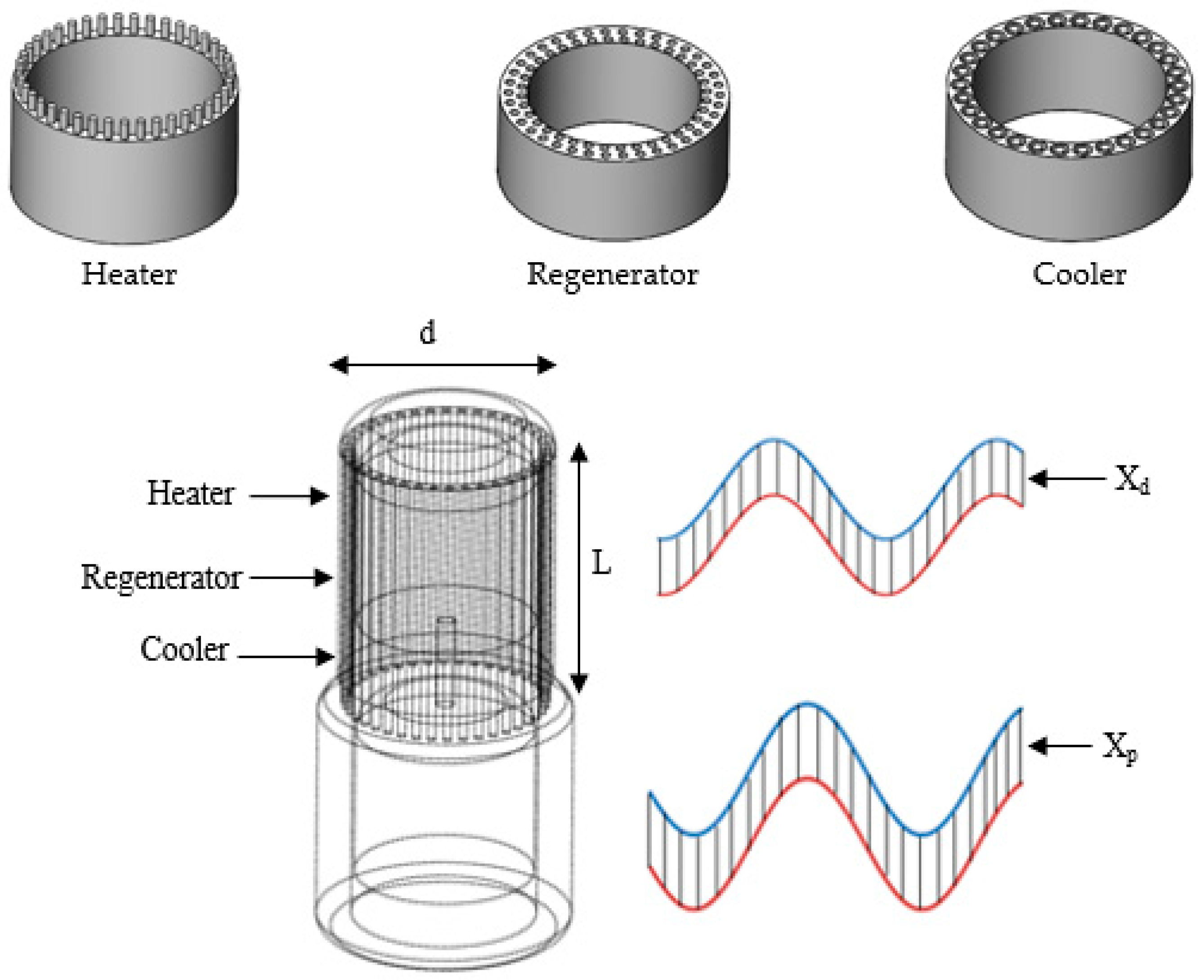
2.3. Specifications for the Free Piston Stirling Engine Model
- The heat losses are considered in the simulation.
- Under static equilibrium, the pressure of the working gas volume corresponds to the block pressure.
- The engine walls’ temperature encompassing the volume of the working gas varies with time.
- Leakage of working gas is not considered and is not expected to occur in the engine.
- The working gas is an ideal gas.
- The regenerator temperature is required to be corresponding to the average temperature of the cooler and heater.
- The FPSE is in a steady state operation.
2.4. Equations Used in the Mathematical Model
3. Results and Discussion
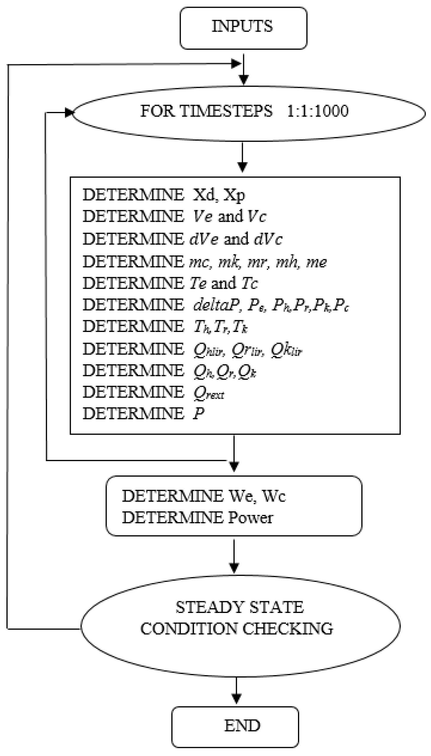
3.1. Numerical Simulation Procedure
3.2. Model Validation
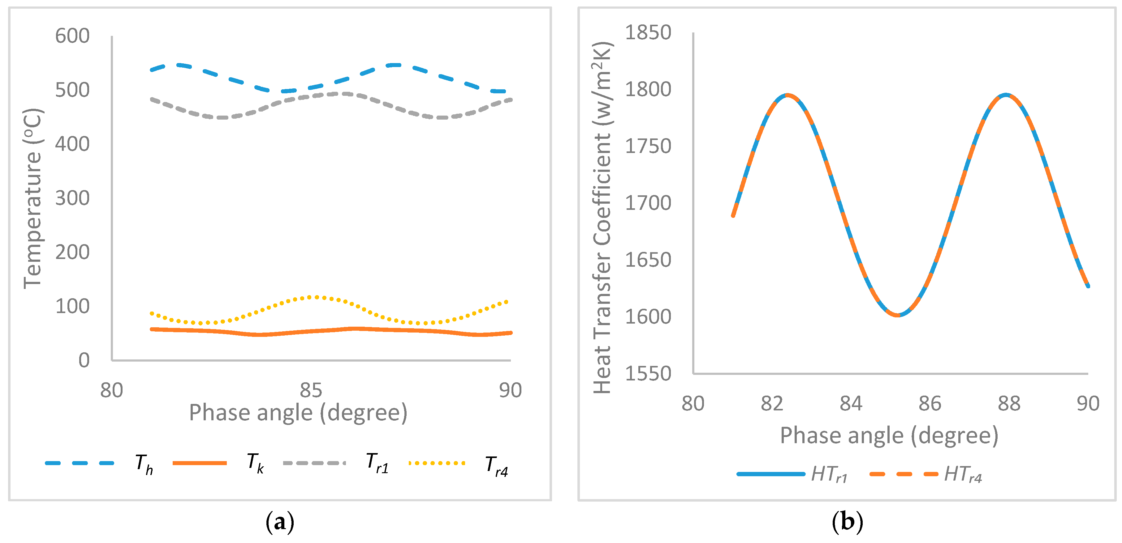
3.3. Numerical Simulation Results
3.4. Sensitivity Analysis of Design Parameters
3.4.1. Influence of Heater Temperature
3.4.2. Influence of Cooler Temperature
3.4.3. Influence of Regenerator Porosity
3.5. Design Implications
4. Conclusions
- The second order quasi-steady model of the FPSE is an advanced methodical approach employed to determine the performance of the engine. The thermal losses, hysteresis losses, temperature variation, working fluid properties and the physical and geometrical properties are considered which described accurately the heat and mass transfer processes in the system and provided a better understanding of the engine’s working process. The engine is split into number of control volumes in which the heat transfer between the working gas and chamber walls including the temperature variation of the chambers are taken into account. Especially in the first simulation, the comparison with the experimental output shows the quasi-steady model predicted an error of 0.4% and 0.3% both in the net work and output power, an error of 4.7% in the amplitude ratio and 36% in phase angle. Also the comparison with the evaluation published in literature indicates that the proposed model is suitable for different conditions. Hence, the model revealed a high accuracy of the FPSEs performance.
- The stable operation of the FPSE can be determined with a careful systematic approach to obtaining the accurate damping load of the piston and displacer as employed in this study.
- The geometry and features of the heater and cooler’s temperature influence on the regenerator based on the design parameters indicate considerable effects on the performance characteristics of the regenerator effectiveness in terms of output power, efficiency, thermal losses and temperature variation.
- The temperature distribution in different parts of the regenerator shows that accurate calculation is required to obtain the heat transfer, heat losses and regenerator temperature. It is observed that at the working gas temperature of 514.3 °C in the heater and 49.8 °C in the cooler, the FPSE resulted to a power output of 996.7 W at a thermal efficiency of 23%.
- The performance of the FPSE is particularly sensitive to the geometry and characteristics of heat exchangers. The influence of the heater and cooler on the engine’s performance is of considerable measure. Especially the regenerator porosity, gradual increment from 0.6 to 0.75 increased the power output and net work of the FPSE, then a further increase reduced the performance of the engine due to increase in the hydraulic resistance in the regenerator, while the increase in the regenerator porosity reduced the thermal efficiency due to the increase in the internal and external conduction losses in the regenerator.
Author Contributions
Conflicts of Interest
Nomenclature
| Cross-sectional area of the piston () | |
| Cross-sectional area of the displacer () | |
| Spring stiffness of displacer (N/m) | |
| Spring stiffness of piston (N/m) | |
| Specific heat at constant pressure (J/kgK) | |
| Specific heat at constant volume (J/kgK) | |
| Damping load of displacer (Ns/m) | |
| Damping load of piston (Ns/m) | |
| D | Diameter (m) |
| l | Length (m) |
| 1-4 | Parts of the regenerator |
| Mass flow rate from the first part of the regenerator to the heater (kg/s) | |
| Mass flow from the cooler to the fourth part of the regenerator (kg/s) | |
| Mass flow rate from the compression space to the cooler (kg/s) | |
| Mass flow rate from heater to expansion space (kg/s) | |
| diss | Heat loss due to the flow friction in the regenerator (W) |
| Thermal conductivity (W/mk) | |
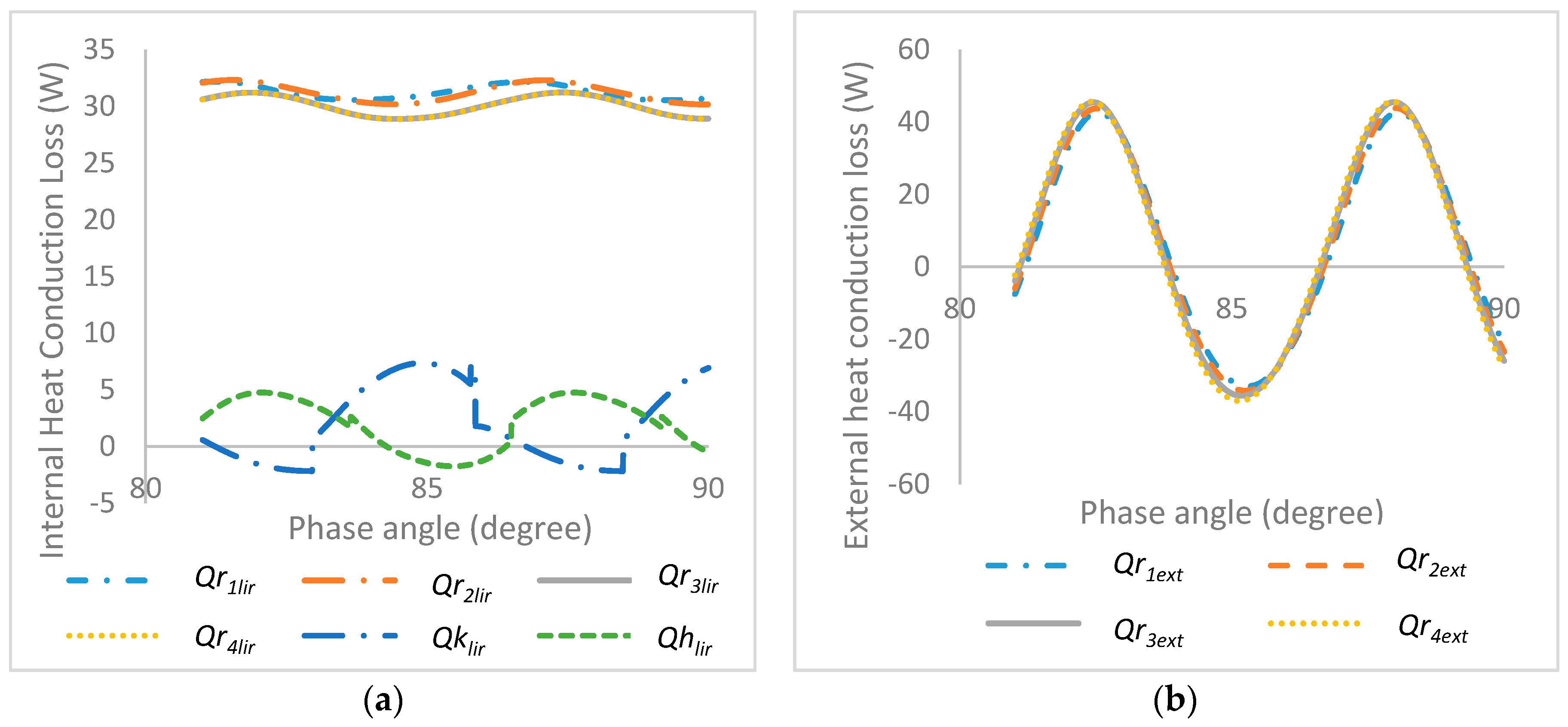
| lir | Heat loss by internal conduction (W) |
| ext | Heat loss by external conduction (W) |
| Mass of the displacer | |
| mp | Mass of the piston |
| Cooler temperature (K) | |
| Regenerator temperature (K) | |
| Heater temperature (K) | |
| Temperature of working gas from compression space to cooler (K) | |
| Temperature of working gas from heater to expansion space (K) | |
| Temperature of working gas from regenerator to heater (K) | |
| Temperature of working gas from cooler to regenerator (K) | |
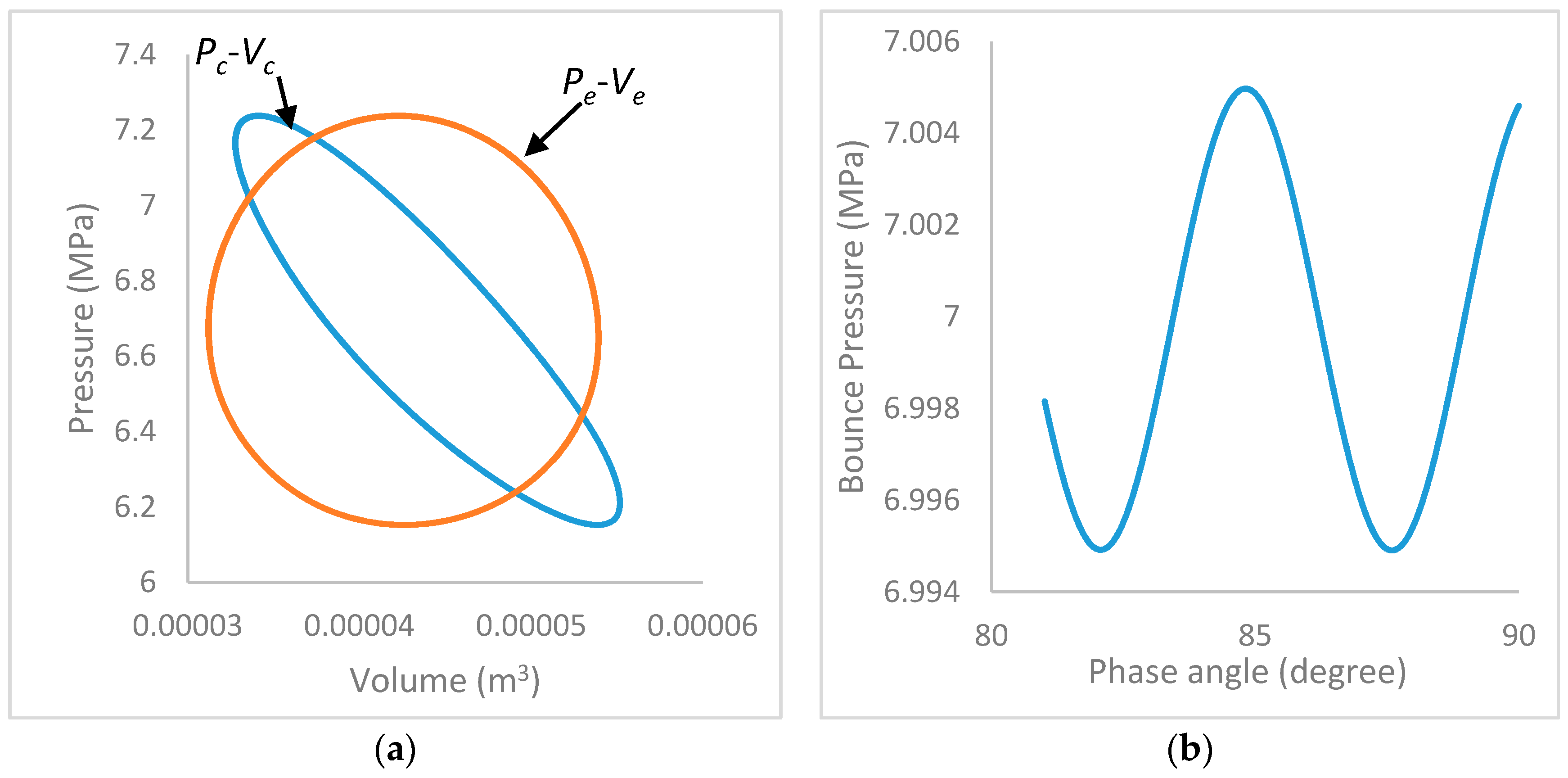
| Bounce space volume ) | |
| Volume of the regenerator ) | |
| Volume of the heater ) | |
| Volume of the cooler ) | |
| Compression space clearance volume ) | |
| Expansion space clearance volume ) | |
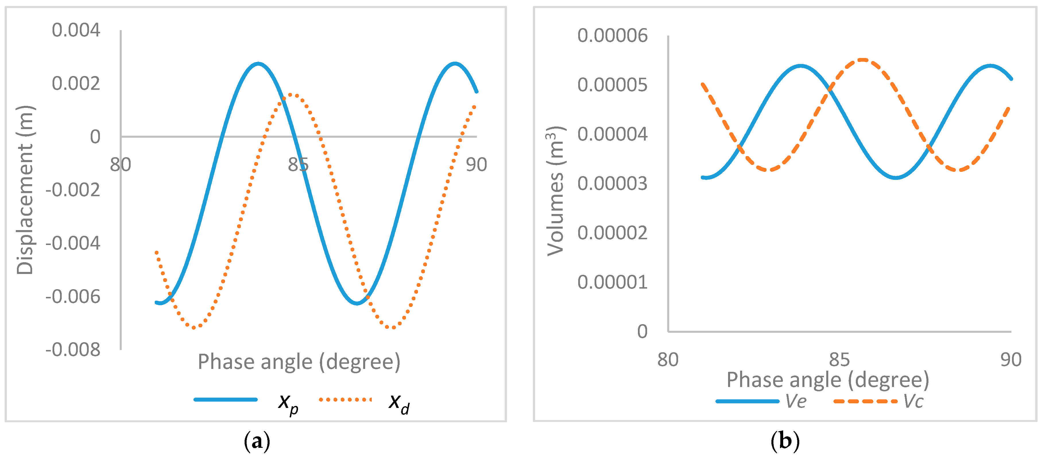
| xp | Displacement of piston () |
| Velocity of piston () | |
| Acceleration of piston | |
| Displacement of displacer () | |
| Velocity of displacer () | |
| Acceleration of displacer (m/s2) | |
| R | Gas constant value |
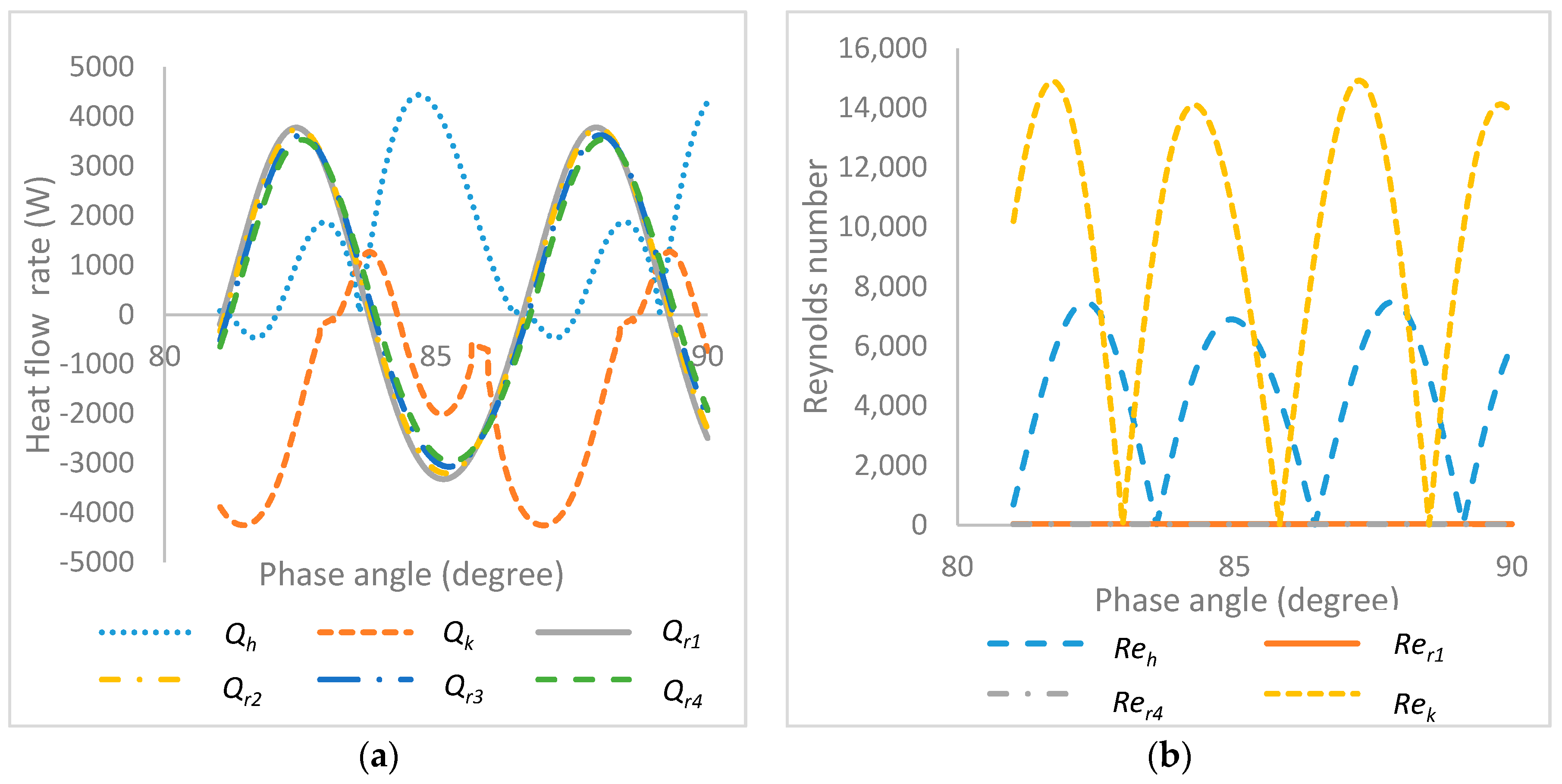
| Re | Reynolds number |
| Q | Heat transfer rate (W) |
| Free surface area () | |
| Pe | Pressure in expansion space (Pa) |
| Pc | Pressure in compression space (Pa) |
| FPSE | Free piston Stirling engine |
| CFD | Computational fluid dynamics |
References
- Rogdakis, E.D.; Bormpilas, N.A.; Koniakos, I.K. A thermodynamic study for the optimization of stable operation of free piston Stirling engines. Energy Convers. Manag. 2004, 45, 575–593. [Google Scholar] [CrossRef]
- Riofrio, J.A.; Al-Dakkan, K.; Hofacker, M.E.; Barth, E.J. Control-based design of free-piston Stirling engines. In Proceedings of the 2008 American Control Conference, Seattle, WA, USA, 11–13 June 2008; pp. 1533–1538. [Google Scholar]
- Bégota, S.; Layes, G.; Lanzetta, F.; Nika, P. Stability analysis of free piston Stirling engines. Eur. Phys. J. Appl. Phys. 2013, 61. [Google Scholar] [CrossRef]
- Sowale, A. Modelling and Optimisation of a Free Piston Stirling Engine for Micro-CHP Applications. Ph.D. Thesis, Northumbria University, Newcastle upon Tyne, UK, 2015. [Google Scholar]
- Formosa, F.; Frechette, L.G. Scaling laws for free piston Stirling engine design: Benefits and challenges of miniaturization. Energy 2013, 57, 796–808. [Google Scholar] [CrossRef]
- Chmielewski, A.; Guminski, R.; Maczak, J. Dynamic model of a free-piston Stirling engine with four degrees of freedom combined with the thermodynamic submodel. In Proceedings of the 2016 21st International Conference on Methods and Models in Automation and Robotics (MMAR), Miedzyzdroje, Poland, 29 August–1 September 2016; pp. 583–588. [Google Scholar]
- Jia, B.; Smallbone, A.; Feng, H.; Tian, G.; Zuo, Z.; Roskilly, A.P. A fast response free-piston engine generator numerical model for control applications. Appl. Energy 2016, 162, 321–329. [Google Scholar] [CrossRef]
- Boucher, J.; Lanzetta, F.; Nika, P. Optimization of a dual free piston Stirling engine. Appl. Therm. Eng. 2007, 27, 802–811. [Google Scholar] [CrossRef]
- Mikalsen, R.; Roskilly, A.P. Performance simulation of a spark ignited free-piston engine generator. Appl. Therm. Eng. 2008, 28, 1726–1733. [Google Scholar] [CrossRef]
- Jia, B.; Zuo, Z.; Tian, G.; Feng, H.; Roskilly, A.P. Development and validation of a free-piston engine generator numerical model. Energy Convers. Manag. 2015, 91, 333–341. [Google Scholar] [CrossRef]
- Mao, J.; Zuo, Z.; Li, W.; Feng, H. Multi-dimensional scavenging analysis of a free-piston linear alternator based on numerical simulation. Appl. Energy 2011, 88, 1140–1152. [Google Scholar] [CrossRef]
- Zhang, C.; Li, K.; Sun, Z. Modeling of piston trajectory-based HCCI combustion enabled by a free piston engine. Appl. Energy 2015, 139, 313–326. [Google Scholar] [CrossRef]
- Jia, B.; Tian, G.; Feng, H.; Zuo, Z.; Roskilly, A.P. An experimental investigation into the starting process of free-piston engine generator. Appl. Energy 2015, 157, 798–804. [Google Scholar] [CrossRef]
- Xiao, J.; Li, Q.; Huang, Z. Motion characteristic of a free piston linear engine. Appl. Energy 2010, 87, 1288–1294. [Google Scholar] [CrossRef]
- Wu, W.; Hu, J.; Yuan, S. Semi-analytical modelling of a hydraulic free-piston engine. Appl. Energy 2014, 120, 75–84. [Google Scholar] [CrossRef]
- Yang, Q.; Luo, E.; Dai, W.; Yu, G. Thermoacoustic model of a modified free piston Stirling engine with a thermal buffer tube. Appl. Energy 2012, 90, 266–270. [Google Scholar] [CrossRef]
- Kim, J.; Bae, C.; Kim, G. Simulation on the effect of the combustion parameters on the piston dynamics and engine performance using the Wiebe function in a free piston engine. Appl. Energy 2013, 107, 446–455. [Google Scholar] [CrossRef]
- Ureli, I. Stirling Cycle Engine Analysis; A. Hilger: Bristol, UK, 1984. [Google Scholar]
- Thomas, B.; Pittman, D. Update on the evaluation of different correlations for the flow friction factor and heat transfer of Stirling engine regenerators. In Proceedings of the 35th Intersociety Energy Conversion Engineering Conference and Exhibit, Las Vegas, NV, USA, 24–28 July 2000; Volume 1, pp. 76–84. [Google Scholar]
- Kraitong, K. Numerical Modelling and Design Optimisation of Stirling Engines for Power Production. Ph.D. Thesis, Northumbria University, Newcastle upon Tyne, UK, 2014. [Google Scholar]
- Asnaghi, A.; Ladjevardi, S.M.; Saleh Izadkhast, P.; Kashani, A.H. Thermodynamics Performance Analysis of Solar Stirling Engines. ISRN Renew. Energy 2012, 2012, 321923. [Google Scholar] [CrossRef]


| Parameters | Expression |
|---|---|
| Motion of displacer | |
| Motion of piston | ) |
| Pressure | |
| Expansion volume | |
| Compression volume | |
| Expansion space temperature | |
| Compression space temperature | |
| Temperature of regenerator’s parts | |
| Energy conservation equations applied to the control volumes | |
| Friction factor of regenerator | |
| Coefficient of heat transfe | |
| Internal heat conduction loss | |
| External heat conduction loss | |
| Heat transfer in heat exchangers | |
| Derivative of total pressure | |
| Work done | |
| Output power |
| Parameters | Boundary Conditions |
|---|---|
| Temperature | If
mck’ > 0 then Tck = Tc else Tck = Tk If mhe’ > 0 then The = Th else The = Te |
| Mass flow rate from heater to expansion space | If , If |
| Mass flow rate from regenerator to heater | If If |
| Mass flow rate from cooler to regenerator | If If |
| Mass flow rate from compression space to cooler | If If |
| Parameters | Heater | Regenerator | Cooler |
|---|---|---|---|
| Number of tubes | 35 | - | 125 |
| Porosity of Regenerator | - | 0.85 | - |
| Length (m) | 0.0792 | 0.06446 | 0.1834 |
| Diameter (m) | 0.0025 | 0.0025 | 0.0025 |
| Regenerator Matrix | - | 4 | - |
| Engine Data | Value |
|---|---|
| Mean Pressure (bar) | 71 |
| Heater Temperature (°C) | 541.3 |
| Cooler Temperature (°C) | 49.8 |
| Working gas | Helium |
| Oscillating frequency (Hz) | 30 |
| Piston damping load (Nsm−1) | 461.5 |
| Displacer damping load (Nsm−1) | 35.34 |
| Spring stiffness of piston (N/m) | 296,000 |
| Spring stiffness of displacer (N/m) | 25,000 |
| Mass of piston (kg) | 6.2 |
| Mass of displacer (kg) | 0.426 |
| Regenerator volume (cm3) | 56.37 |
| Heater volume (cm3) | 27.33 |
| Cooler volume (cm3) | 20.43 |
| Expansion space clearance volume (m3) | 0.01861 |
| Compression space clearance volume (m3) | 0.01830 |
| Parameters | Experiment RE-1000 | Urieli and Berchowitz | Simulation 1 | Simulation 2 | Error 1 (%) | Error 2 (%) |
|---|---|---|---|---|---|---|
| Frequency (Hz) | 30 | 33.2 | 30 | 33.2 | 0 | 0 |
| Output power (W) | 1000 | 1320 | 996 | 1258 | 0.4 | 4.7 |
| Net work (J) | 33.3 | 39.8 | 33.2 | 37.9 | 0.3 | 4.8 |
| Amplitude ratio | 1.06 | 0.62 | 1.01 | 0.82 | 4.7 | −32 |
| Phase angle (°) | −42.5 | −57.9 | −57.8 | −60.9 | 36 | 5.2 |
| Heater Temperature (°C) | Power Output (W) | Efficiency (%) | Net Work (J) | Qlir (W) | Qrextl (W) | Tr1 (°C) | Tr4 (°C) | mh (×10−4) (kg) | mk (×10−4) (kg) | mr (×10−5) (kg) | Reh | Rek | Rer |
|---|---|---|---|---|---|---|---|---|---|---|---|---|---|
| 400 | 36.94 | 10.06 | 1.23 | 8.09 | 0.22 | 654 | 345 | 2.08 | 1.34 | 5.45 | 3278 | 623 | 259 |
| 450 | 187 | 16.59 | 6.24 | 9.05 | 0.51 | 699 | 352 | 2.09 | 1.36 | 5.50 | 3013 | 1640 | 268 |
| 500 | 464 | 19.50 | 15.50 | 9.72 | 1.23 | 735 | 368 | 2.10 | 1.39 | 5.59 | 7183 | 3797 | 296 |
| 550 | 1010 | 22.13 | 33.70 | 10.15 | 2.84 | 760 | 390 | 2.20 | 1.48 | 5.76 | 10,003 | 8001 | 315 |
| 600 | 2006 | 24.27 | 66.90 | 10.36 | 4.52 | 810 | 420 | 2.40 | 1.53 | 6.02 | 12,141 | 11,056 | 352 |
| 650 | 2726 | 28.01 | 90.90 | 11.70 | 6.02 | 819 | 460 | 2.60 | 1.67 | 6.88 | 13,750 | 17,520 | 390 |
| 700 | 3205 | 31.67 | 118.2 | 12.07 | 8.70 | 850 | 417 | 2.90 | 1.74 | 7.72 | 14,274 | 19,241 | 413 |
| 750 | 3871 | 32.98 | 146.0 | 12.94 | 13.25 | 875 | 425 | 3.30 | 1.89 | 8.68 | 14,900 | 24,720 | 457 |
| Cooler Temperature (°C) | Power Output (W) | Efficiency (%) | Net Work (J) | Qlir (W) | Qrextl (W) | Tr1 (°C) | Tr4 (°C) | mh (×10−4) (kg) | mk (×10−4) (kg) | mr (×10−5) (kg) | Reh | Rek | Rer |
|---|---|---|---|---|---|---|---|---|---|---|---|---|---|
| 55 | 924 | 22.4 | 30.8 | 10.33 | 2.52 | 782 | 391 | 2.16 | 1.18 | 5.73 | 13,430 | 6792 | 291 |
| 60 | 711 | 21.2 | 23.7 | 10.25 | 1.67 | 767 | 388 | 2.08 | 1.17 | 5.40 | 11,254 | 5114 | 290 |
| 65 | 618 | 19.1 | 20.6 | 10.21 | 1.42 | 750 | 382 | 2.03 | 1.16 | 5.32 | 8954 | 4578 | 279 |
| 70 | 567 | 15.5 | 18.9 | 10.17 | 1.18 | 744 | 374 | 1.99 | 1.14 | 5.15 | 6947 | 3670 | 272 |
| 75 | 489 | 13.3 | 16.3 | 10.15 | 0.93 | 736 | 352 | 1.96 | 1.13 | 5.13 | 5214 | 3216 | 268 |
| 80 | 417 | 11.6 | 13.9 | 10.13 | 0.75 | 718 | 334 | 1.93 | 1.12 | 5.06 | 4958 | 2751 | 261 |
| 85 | 348 | 10.4 | 11.3 | 10.12 | 0.61 | 709 | 327 | 1.89 | 1.11 | 4.97 | 3821 | 2103 | 254 |
| 90 | 292 | 8.11 | 9.8 | 10.11 | 0.52 | 701 | 308 | 1.88 | 1.10 | 4.91 | 3358 | 1782 | 245 |
| Regenerator Porosity | Power Output (W) | Efficiency (%) | Net Work (J) | Qlir (W) | Qrextl (W) |
|---|---|---|---|---|---|
| 0.6 | 1389 | 38.4 | 57.3 | 10.4 | −1.25 |
| 0.65 | 1433 | 37.0 | 60.0 | 13.0 | −1.19 |
| 0.7 | 1476 | 36.0 | 61.5 | 37.0 | 1.5 |
| 0.75 | 1462 | 34.3 | 61.3 | 34.1 | 1.9 |
| 0.8 | 1417 | 30.7 | 58.7 | 25.0 | 2.5 |
| 0.85 | 1313 | 25.2 | 55.0 | 18.0 | 3.6 |
| 0.9 | 1076 | 17.7 | 45.2 | 12.7 | 5.8 |
© 2018 by the authors. Licensee MDPI, Basel, Switzerland. This article is an open access article distributed under the terms and conditions of the Creative Commons Attribution (CC BY) license (http://creativecommons.org/licenses/by/4.0/).
Share and Cite
Sowale, A.; Kolios, A.J. Thermodynamic Performance of Heat Exchangers in a Free Piston Stirling Engine. Energies 2018, 11, 505. https://doi.org/10.3390/en11030505
Sowale A, Kolios AJ. Thermodynamic Performance of Heat Exchangers in a Free Piston Stirling Engine. Energies. 2018; 11(3):505. https://doi.org/10.3390/en11030505
Chicago/Turabian StyleSowale, Ayodeji, and Athanasios J. Kolios. 2018. "Thermodynamic Performance of Heat Exchangers in a Free Piston Stirling Engine" Energies 11, no. 3: 505. https://doi.org/10.3390/en11030505