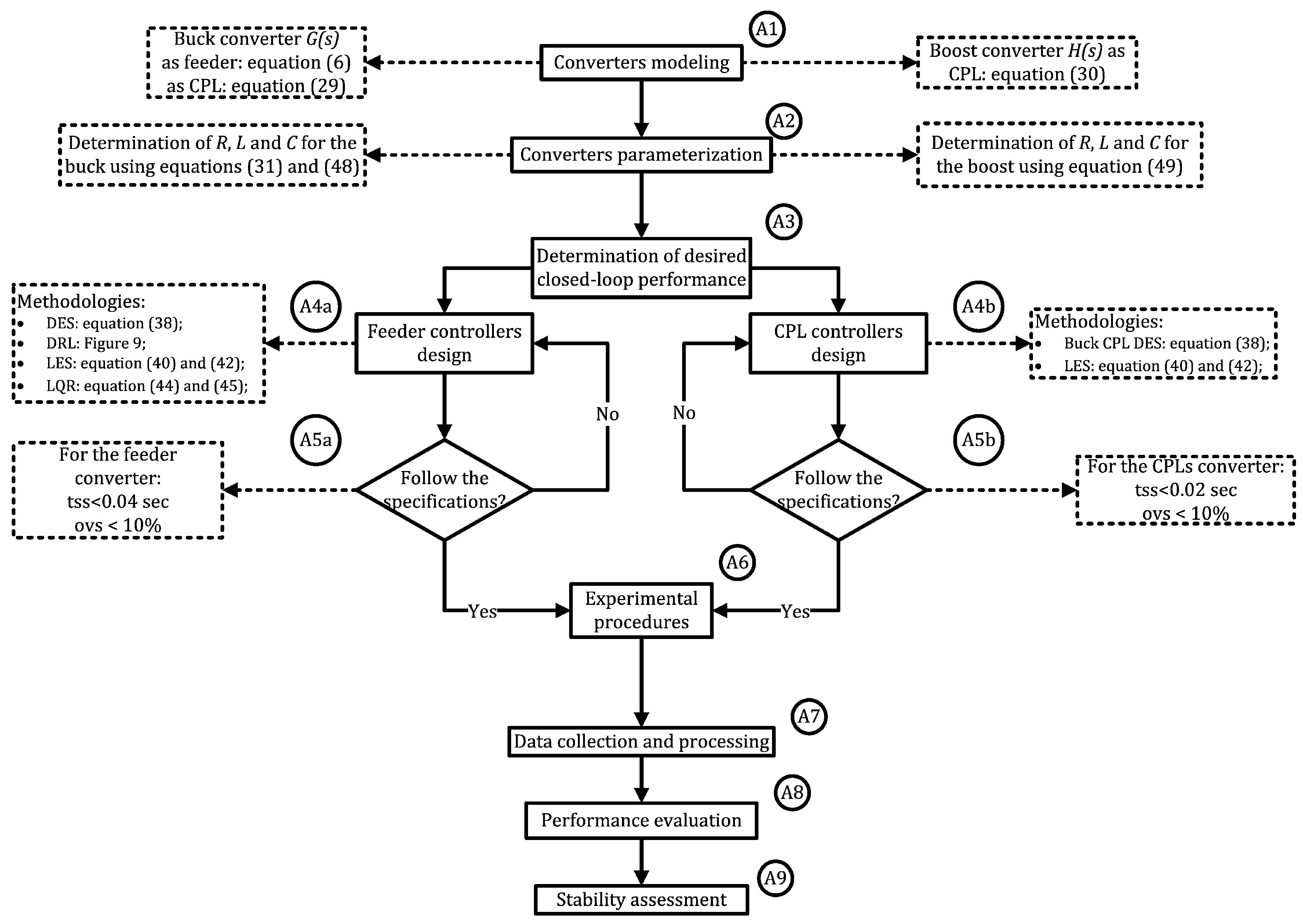
4.1. Feeder Controllers Design
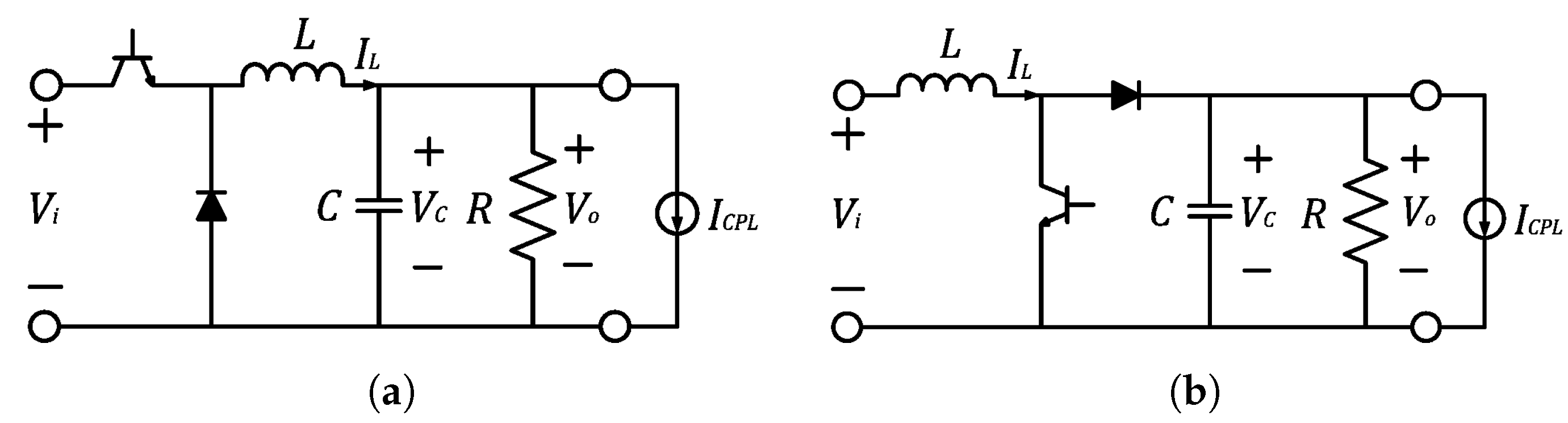
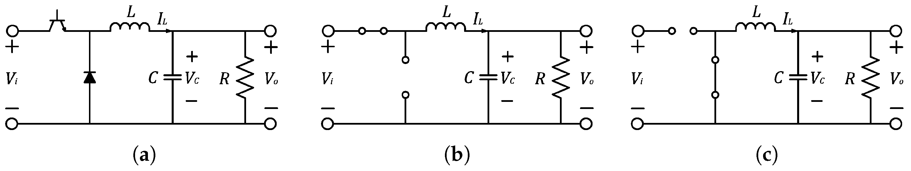
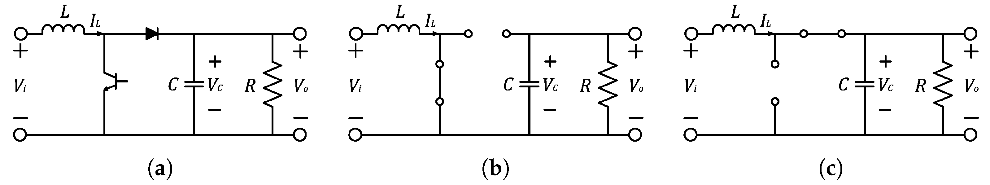
The feeder is designed from the buck converter shown in
Figure 1a. The first step is to determine parameters
R,
L and
C. For this, had available a 12 V voltage source with a maximum current supply of 6 A. The buck converter regulates this voltage for the DC bus with
V. A current ripple
in the inductor below 1 A and a voltage ripple
in the capacitor below 10% of the output voltage was desired. The switching frequency of 20 kHz of the converter was chosen based on the determination of the 1 mH inductor, which required a minimum frequency of 3 kHz for the CCM operation of the converter and a switching frequency below 100 kHz for correct operation of the IGBT used. Therefore, with the help of the set of equations in Equation (
31), the parameters were determined as indicated in
Table 1.
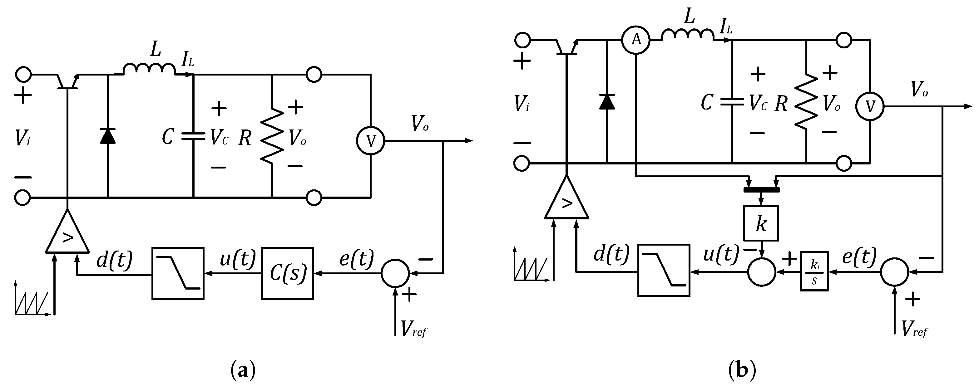
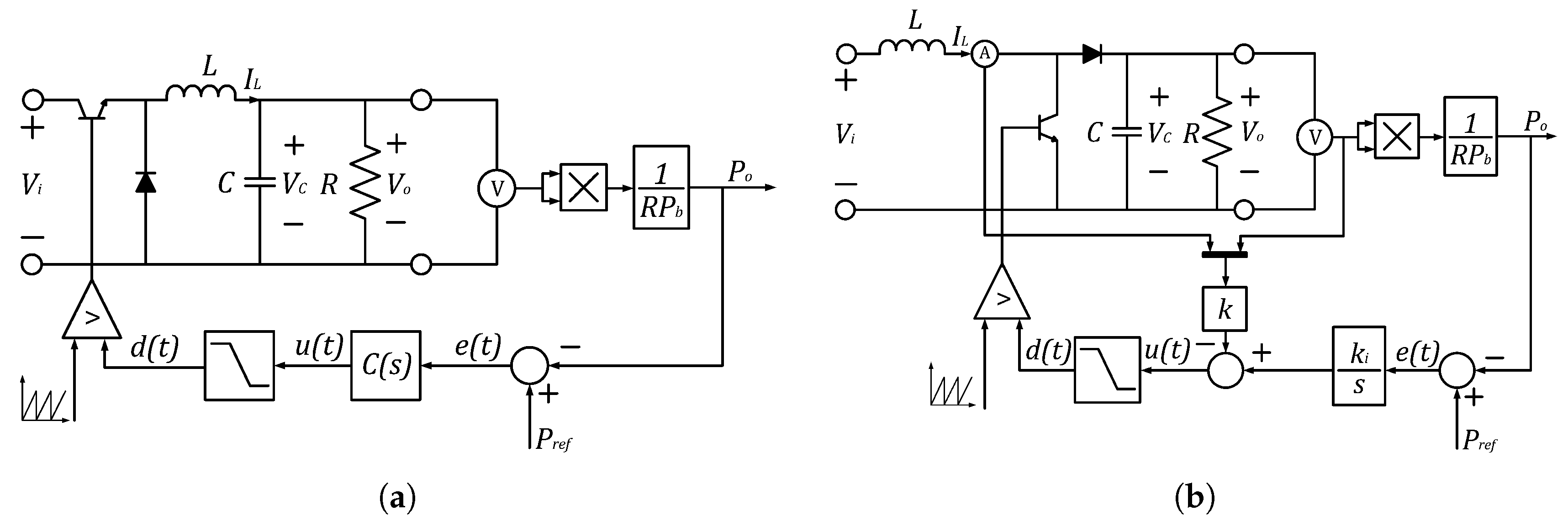
With the converter parameters determined, the next step is to design the controller that ensures system stability in addition to meeting performance specifications. In this sense, two control structures for the feeder project are addressed. The first is the output feedback shown in
Figure 8a. The second structure is the state feedback shown in
Figure 8b. The output feedback structure is based on determining the controller
based on performance specification. In this paper, the controller
is designed by using two techniques. The first is through the Diophantine equation solution (DES) and the second is using the graphical tool of the root locus (DRL). The state feedback structure is designed in order to determine the gains
k and
through the solution of the Lyapunov equation (LES) and through the solution of the Riccati’s equation for designing a linear-quadratic regulator (LQR).
The control design goal is to ensure that the converter has a settling time
less than 0.04 s and a maximum overshoot
less than 10% with the guarantee of zero error at the step. These performance specifications allows to compute the damping coefficient
and natural frequency
as follows.
Finally, the desired polynomial is constructed composed of an auxiliary pole
, as follows. Notice that the gains designed depends on the chosen control structure.
The plant dynamics and the controller for the buck converter is generically described as follows.
In sequel, the closed-loop characteristic polynomial is described by Equation (
36) that should be equivalent to Equation (
33), resulting in the Diophantine Equations (
36) and (
37). The solution of Diophantine equations determines the controller gains by DES.
To ease the compute process, Equation (
37) is rewritten in the matrix form, staying in the form of the Sylvester equation as indicated in Equation (
38).
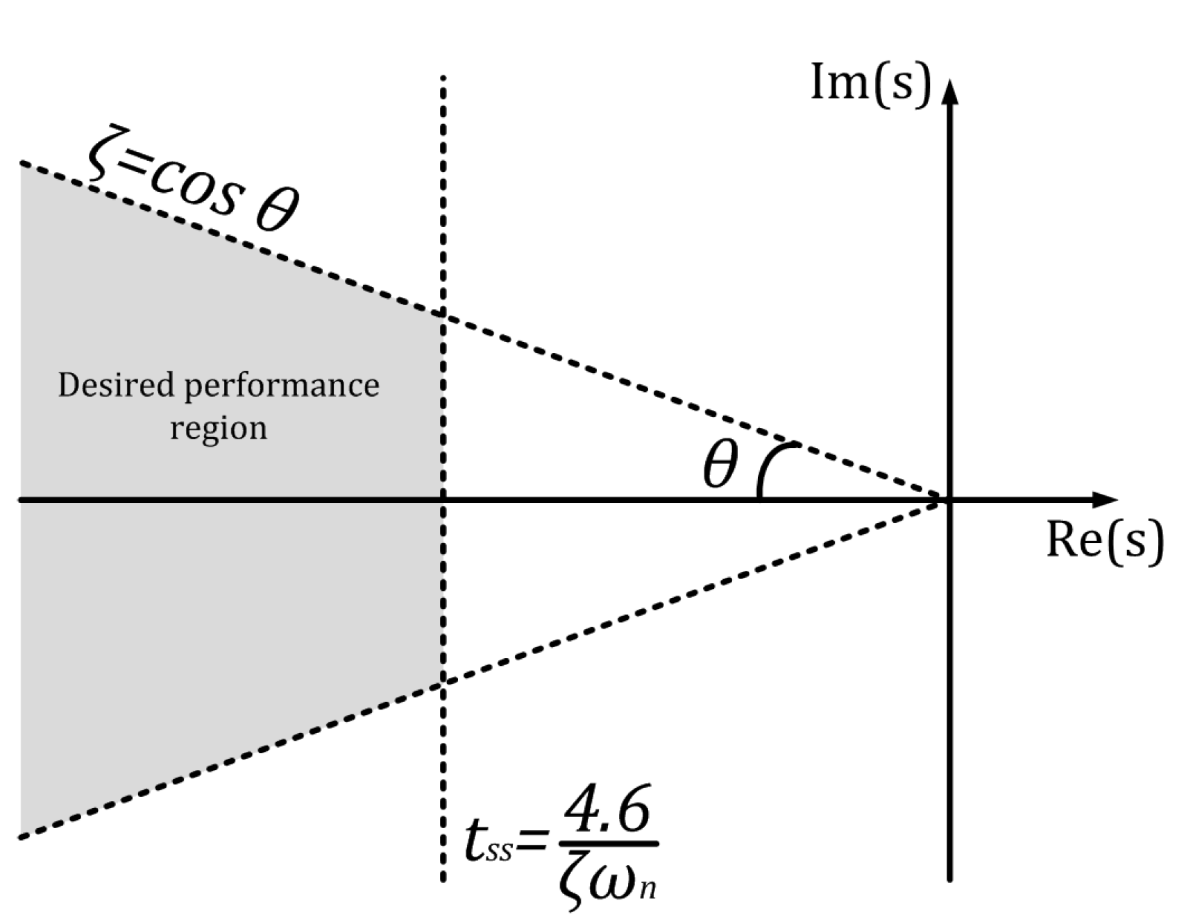
Another way to design the controller is based on the root locus, that is a graphical tool to plot the roots of the characteristic closed-loop polynomial shown in Equation (
36) in
s-plane. Thus, the DRL design specifies the desired performance region from a
and
as shown in
Figure 9 and the gains of
are computed to ensure that the roots are within that region.
For the state feedback structure with robust tracking, the augmented model is obtained to include the error dynamics and gains
and
should be computed. Therefore, the augmented model of the buck converter is described as follows
where
thus, it is possible to compute the controller’s gains by solving the LES
where,
is a matrix whose eigenvalues are the roots of the closed-loop characteristic polynomial and
are initial values where the set
is observable. In particular, the following
F is chosen based on performance specifications (cf. Equation (
32)) to obtain settling time and maximum overshoot lower than the specifications, since the dominant pole is real (
) and about 50 % further from the origin than the desired damped frequency circle, i.e., with radius equal to
.
The solution of Equation (
40) determines the value of
T, which allows compute the
as follows.
Finally, the LQR methodology consists in optimizing the following cost function to design
K:
where, the matrices
and
are gains that allow a trade-off between better performance or better control effort. Notice that Equation (
43) must comply with the Lyapunov criteria described in [
19,
20], and the Riccati equation is derived from in Equation (
44).
Considering the following matrices
Q and
R used to design the gains, and applying in Equation (
45), it is possible to compute the gains to achieve the desired behavior established in Equations (
43) and (
44).
Finally, the designed controllers are digitally implemented, so the controller described in Equation (
35) can be expressed in digital form for a sampling period
ms indicated in Equation (
46) through the exact discretization of matching poles and zeros using the
relationship.
However, the integral gain in the state feedback structure was discretized by using the euler method where
, therefore the integral controller is described by means in Equation (
47).
The digital controller gains for the feeder are summarized in
Table 2 considering the sampling time
ms. The resulting gains are presented in
Table 2. Notice that the
gain should be multiplied by the sampling time to obtain the control law to be embedded in the micro-controller.
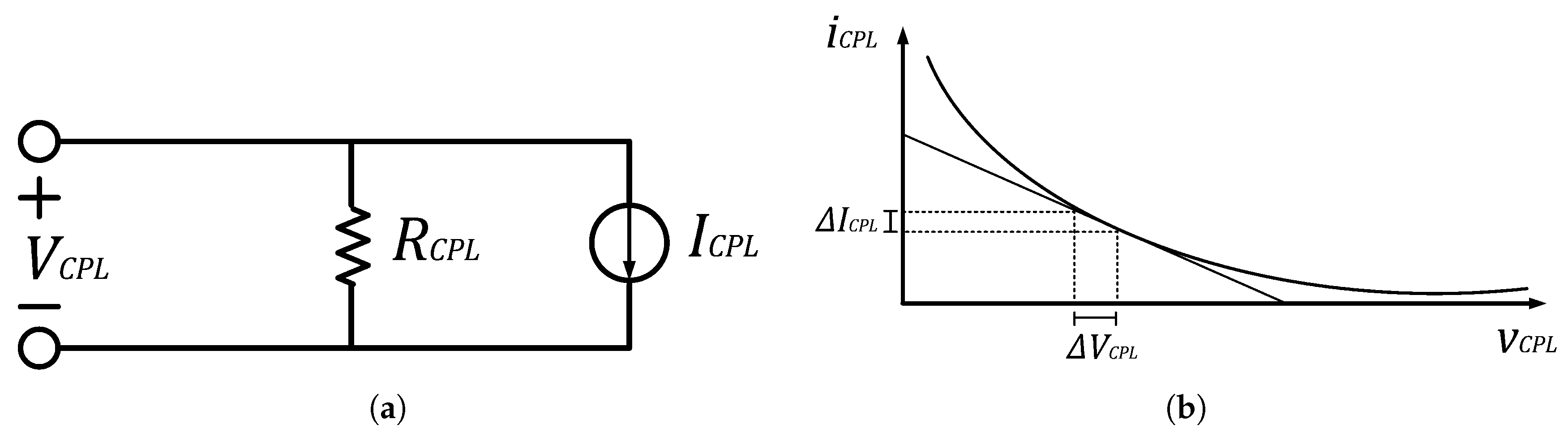
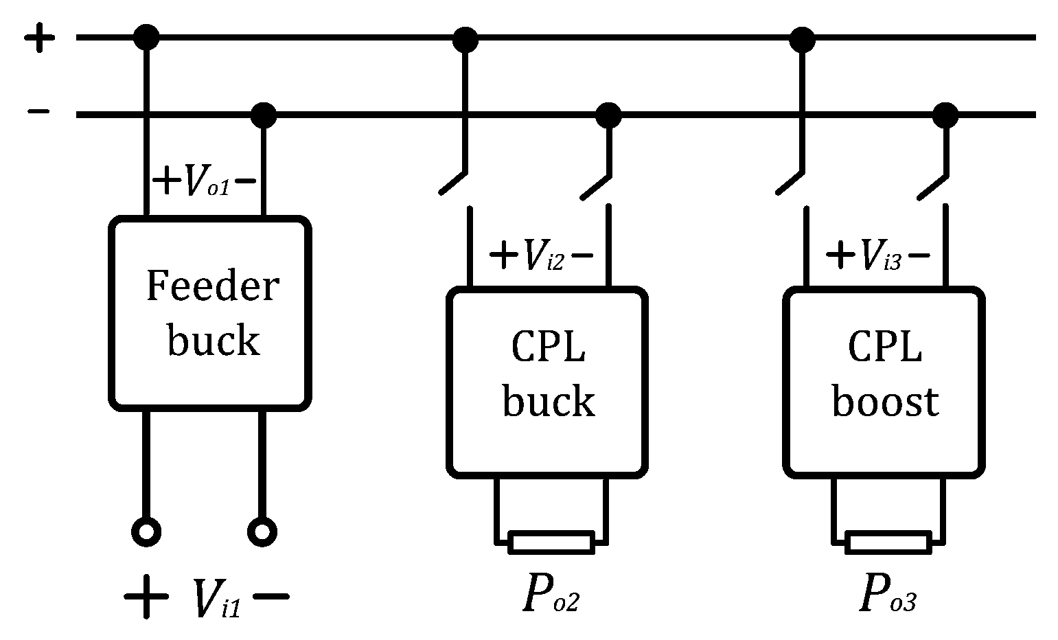
4.2. CPL Design
After the feeder design, the next step is to design the CPLs by using the buck and boost converters. CPLs are designed to be powered by a voltage of 6V to ensure that the demanded current is within the source limitations. For the CPL buck, a current ripple
A and a voltage ripple
% were considered. A
V supply with a switching frequency
kHz. For a duty cycle base
, the output power is specified for
p.u. by means of Equation (
48).
Whereas, for the CPL boost, a current ripple
A and a voltage ripple
% is considered and
V supply with a switching frequency
kHz. For a duty cycle base
, the output power was specified for
p.u., then through the set of equations in Equation (
49).
The parameters of the designed CPL converters are summarized in
Table 3. Finally, the controller gains to ensure the CPL operation of converters are computed. The buck converter is designed by using output feedback structure and the boost converter is designed by using the robust tracking state feedback structure as shown, respectively, in
Figure 7a,b. The design specifications are
s and
% to ensure that the CPL dynamics is faster than the feeder dynamics.
The CPL buck design is carried out from DES in the same way as indicated in the previous
Section 4.1. The CPL boost design is carried out through LES. The gains of CPL controllers are summarized in
Table 4, considering the discretization with sampling period
ms.
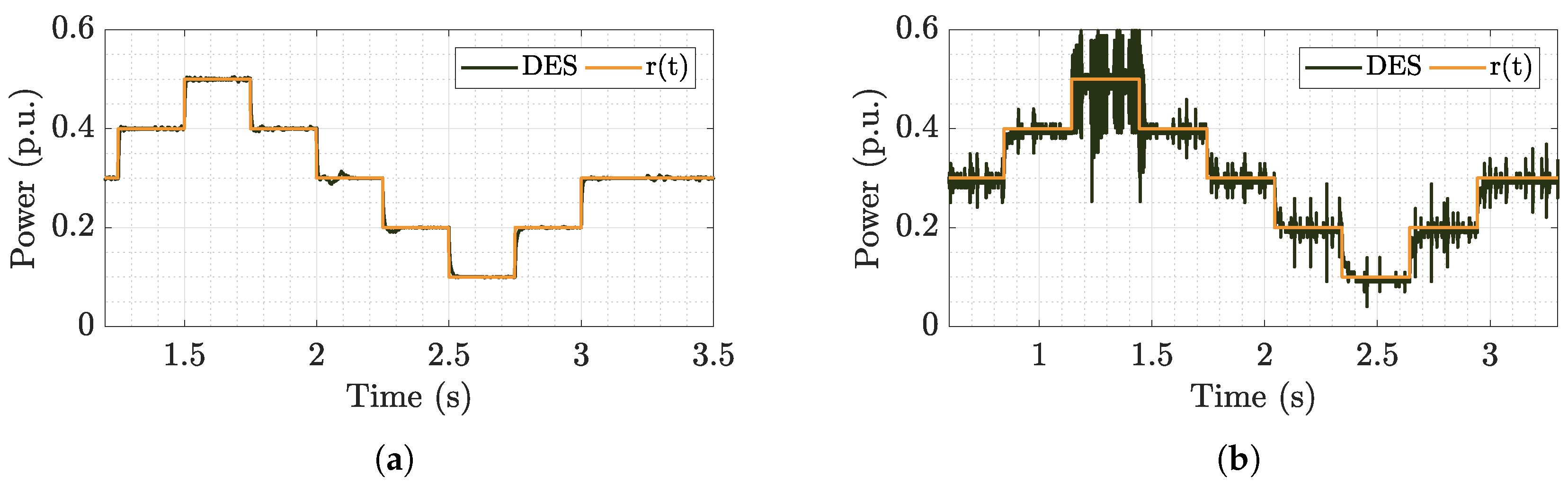
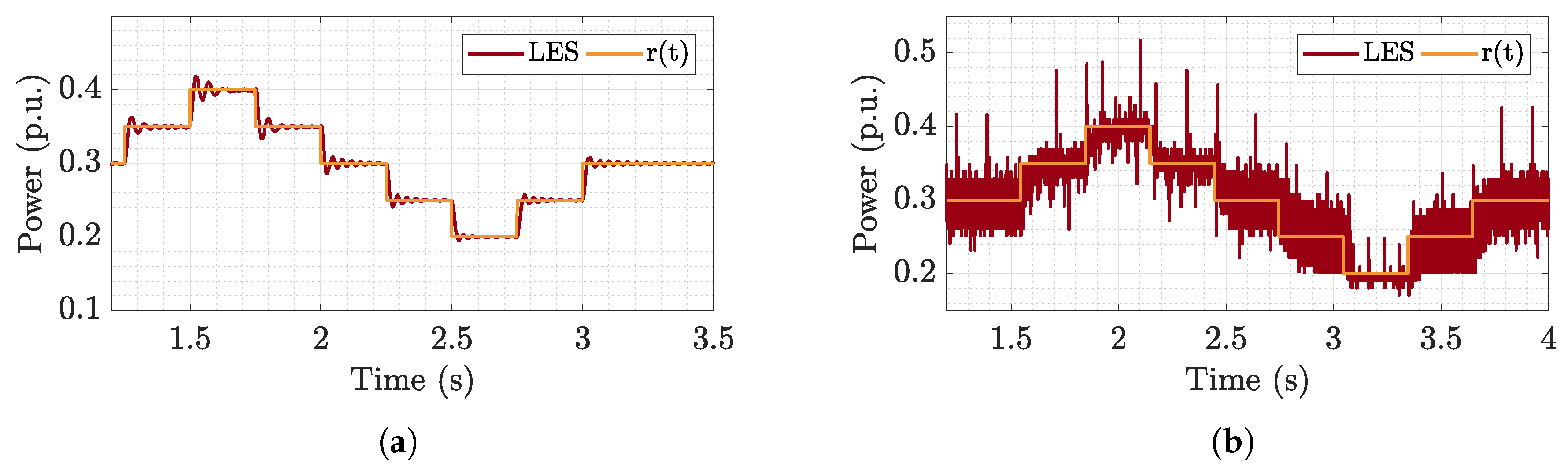
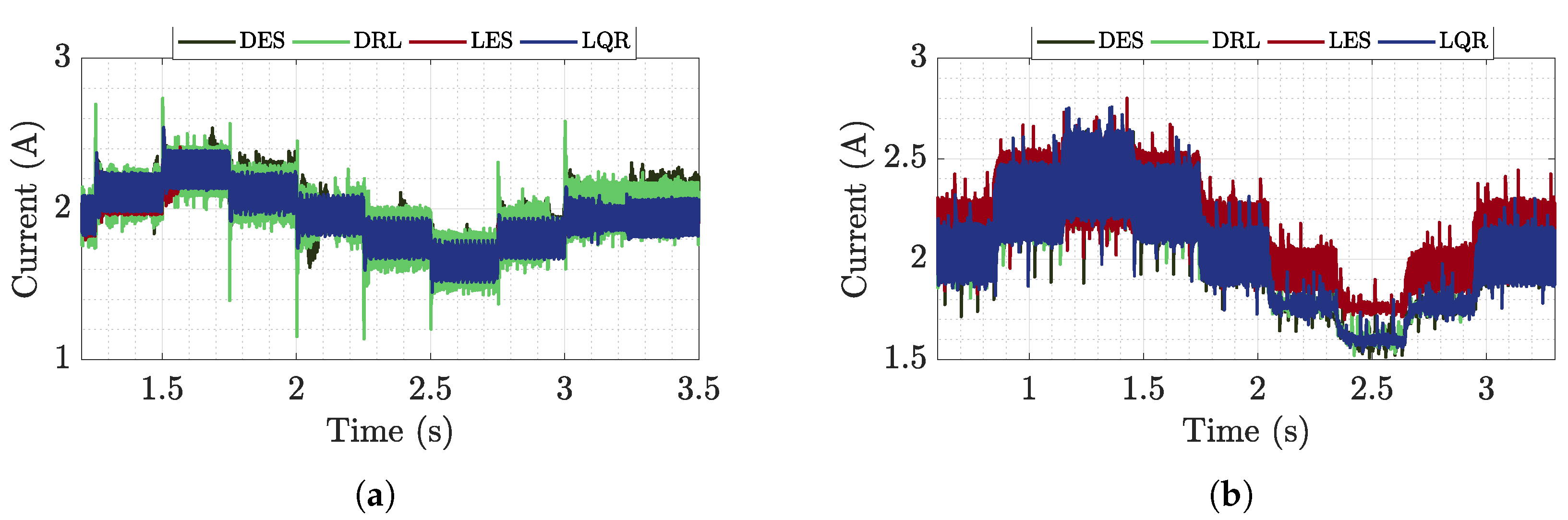
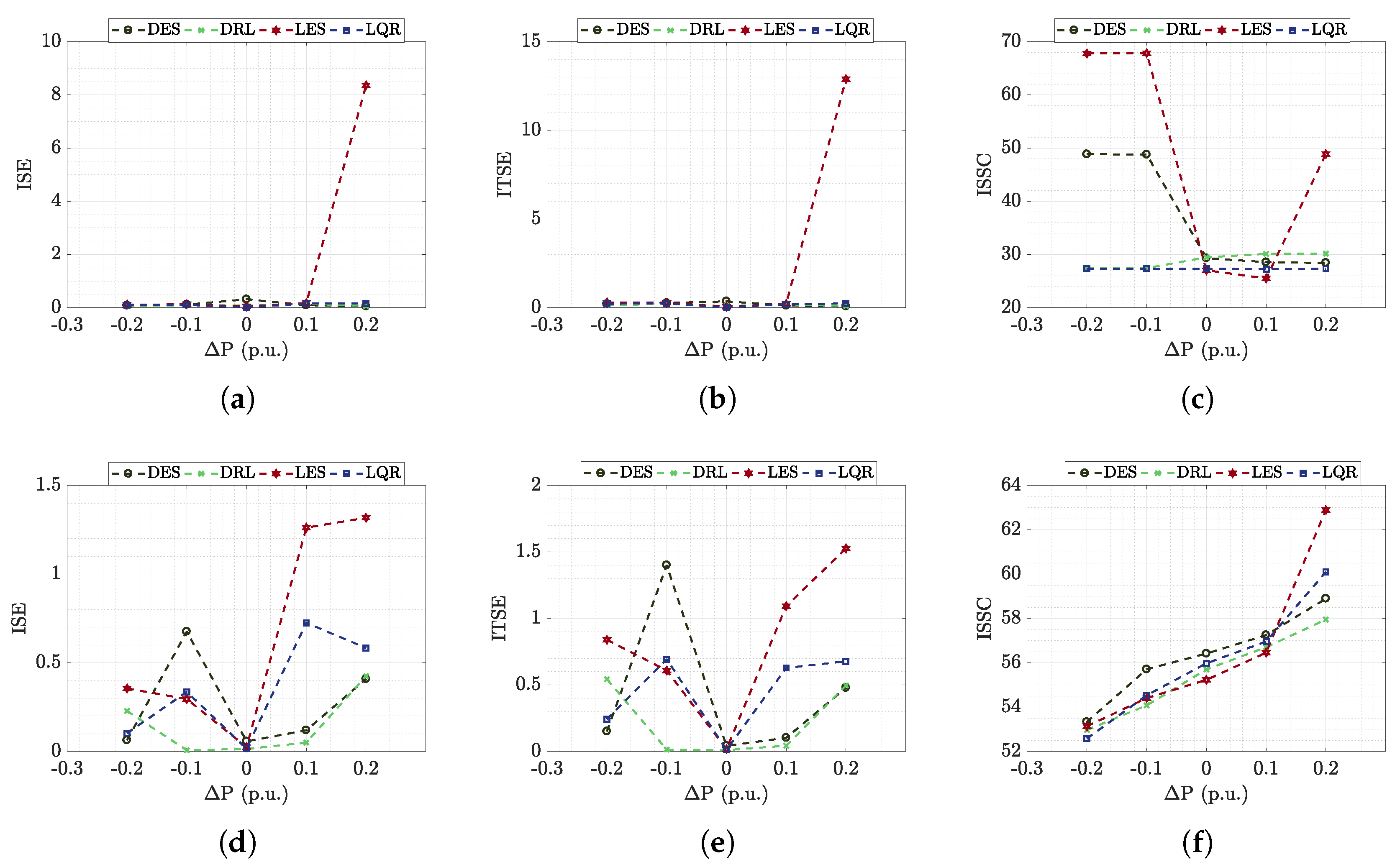
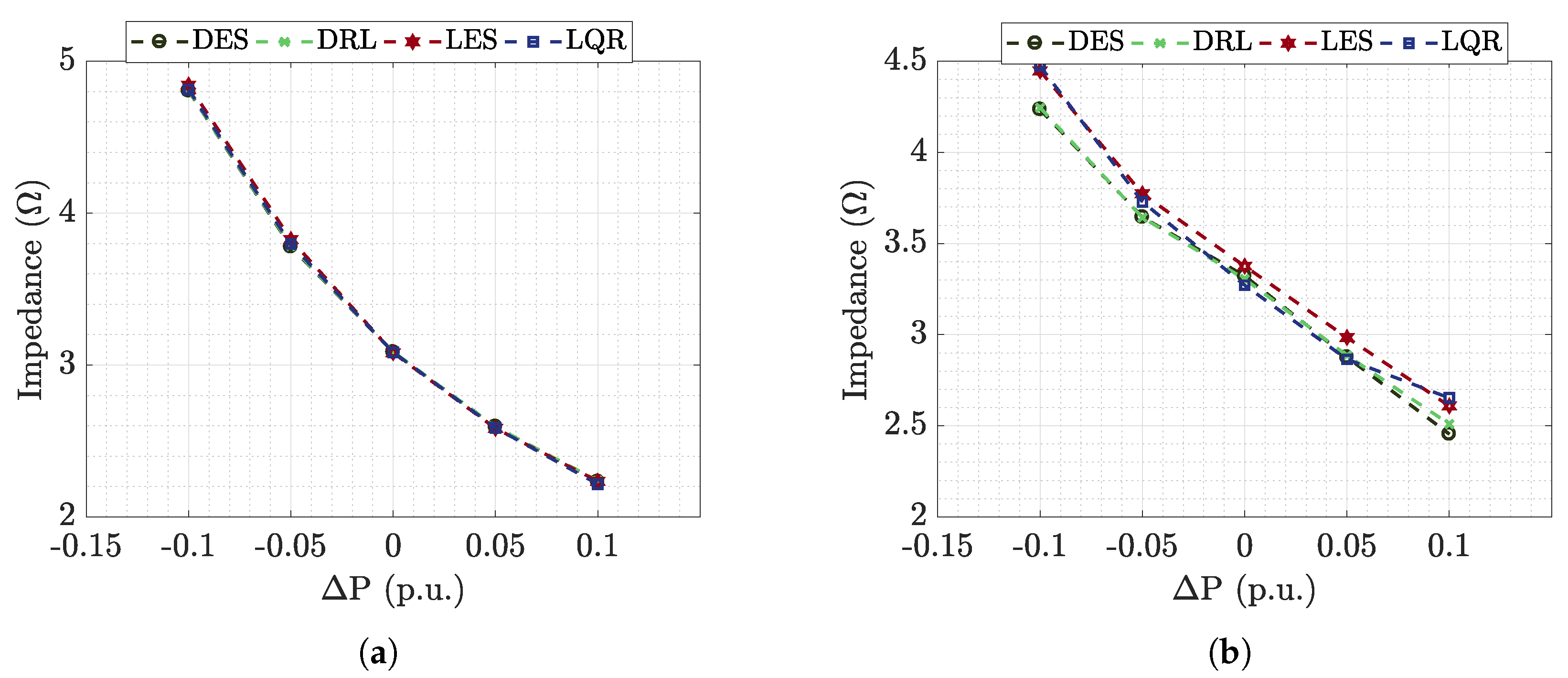
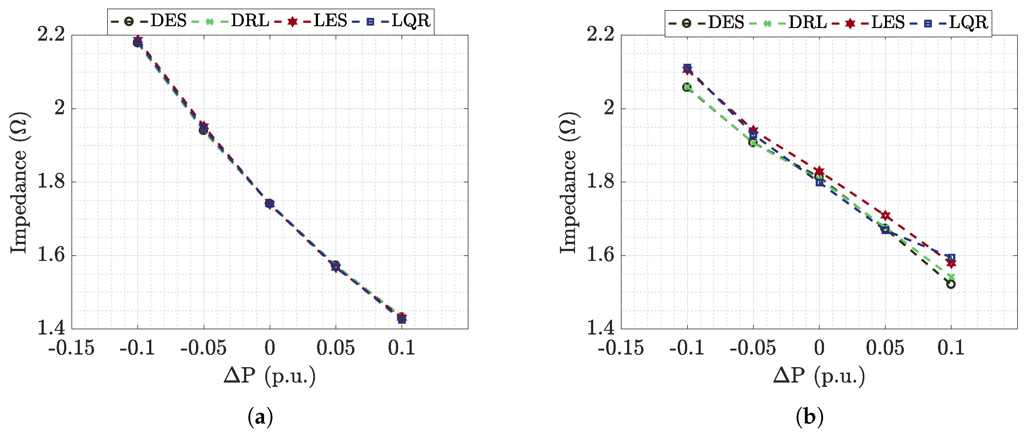
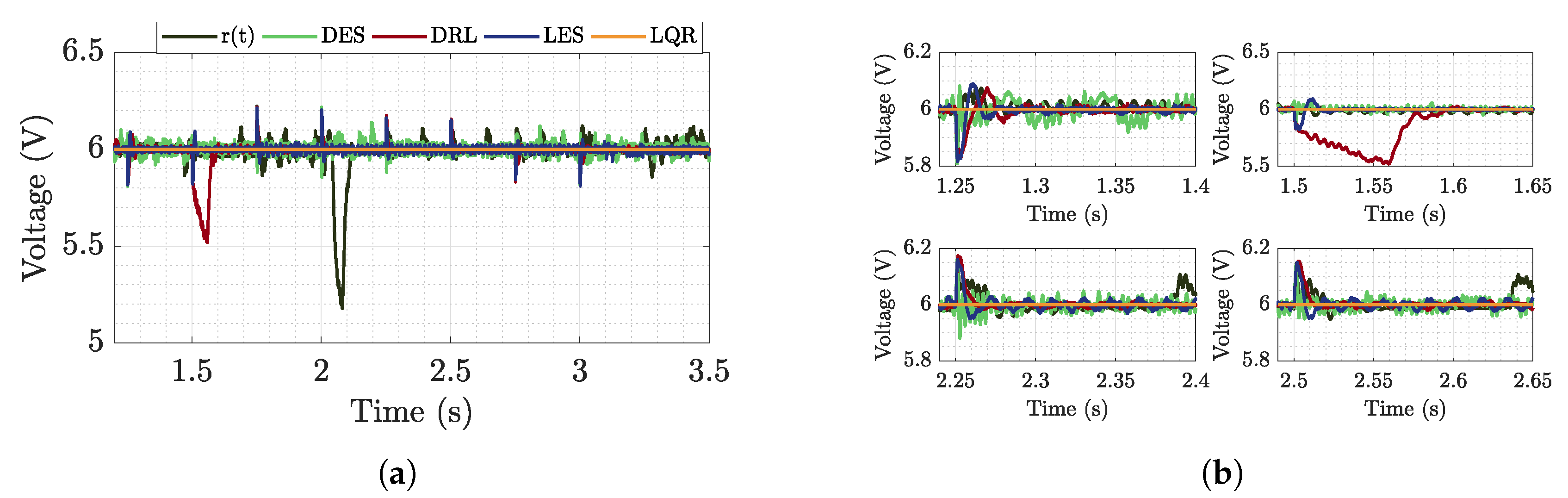
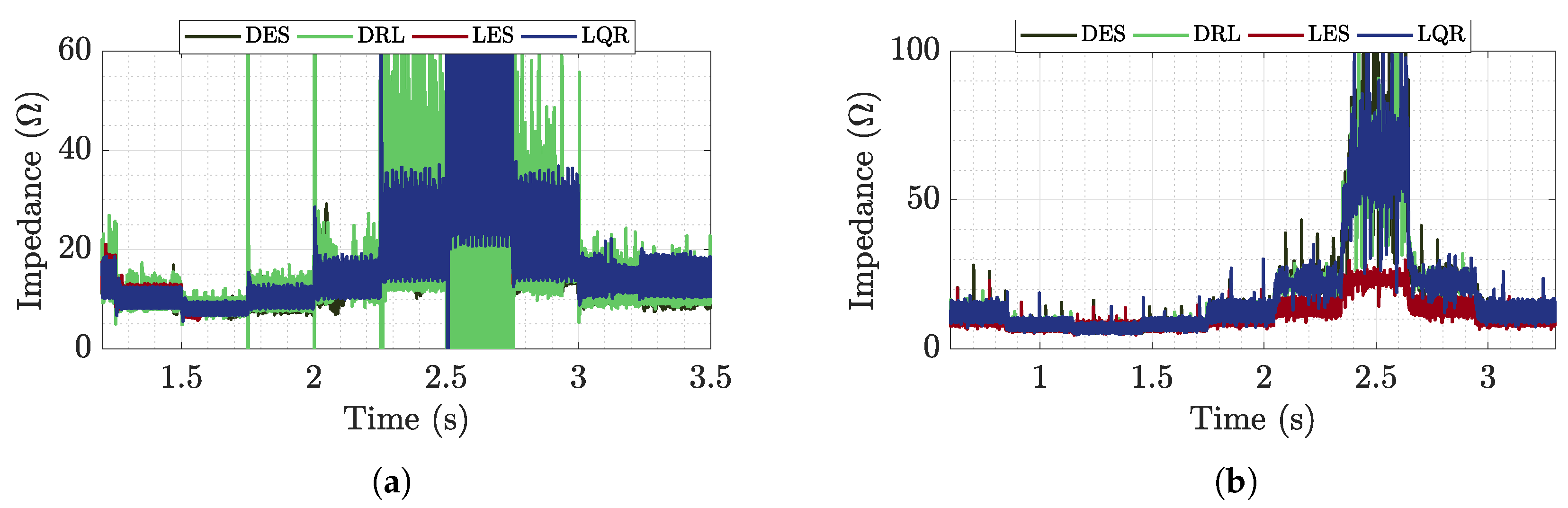
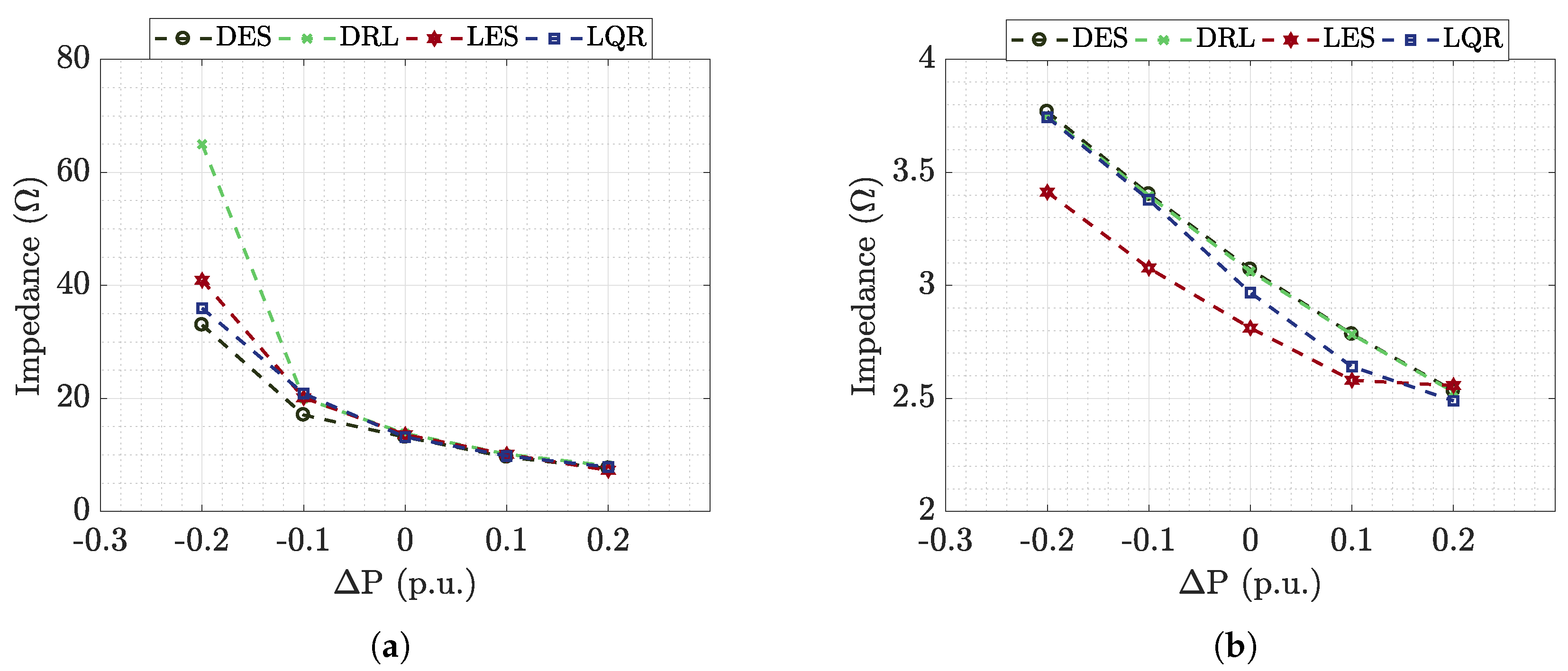
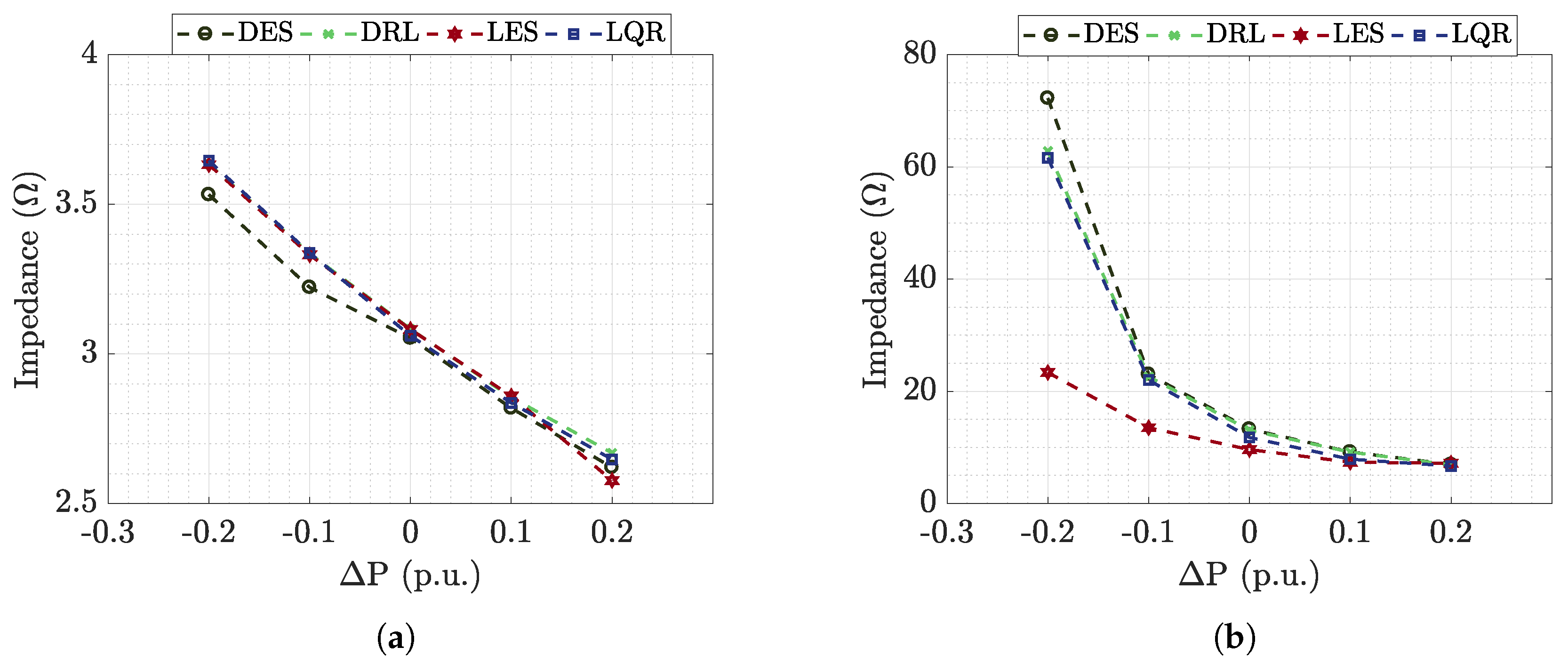
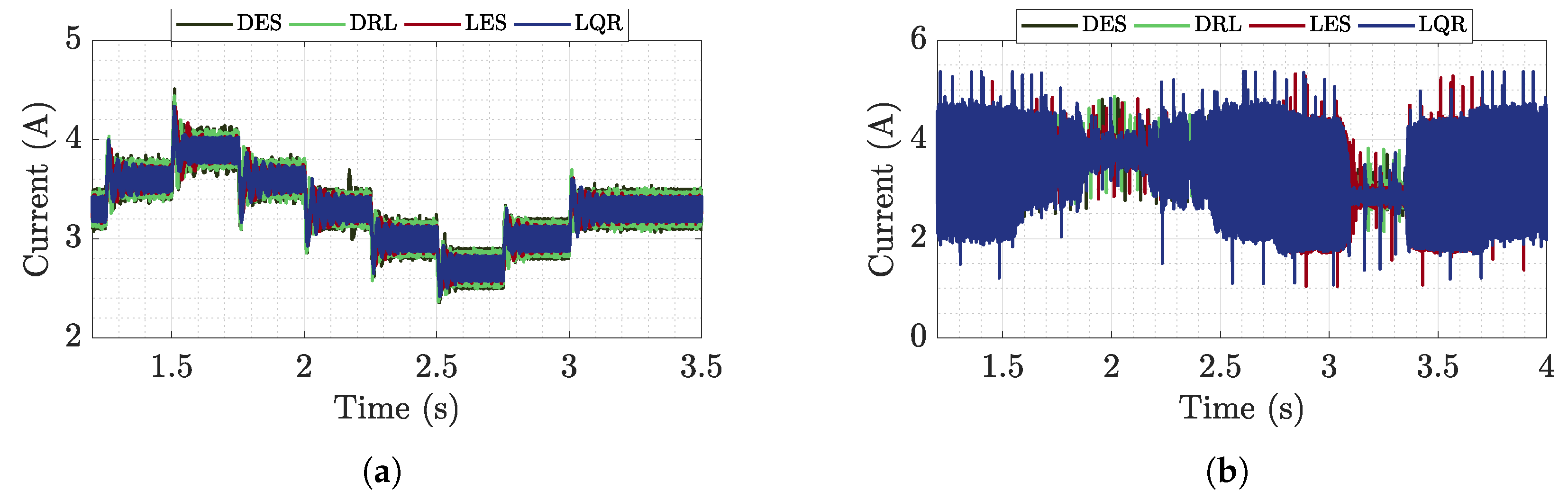
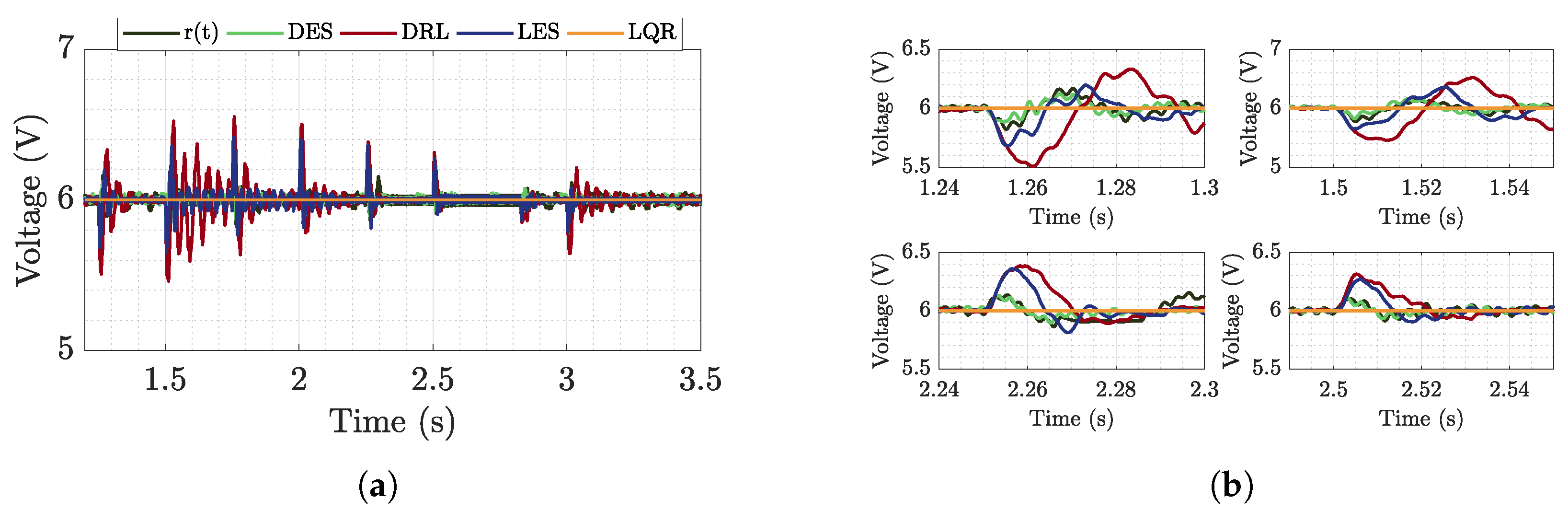
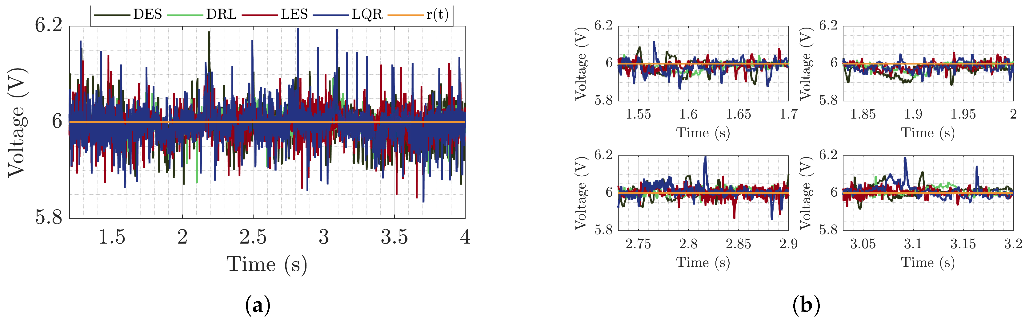
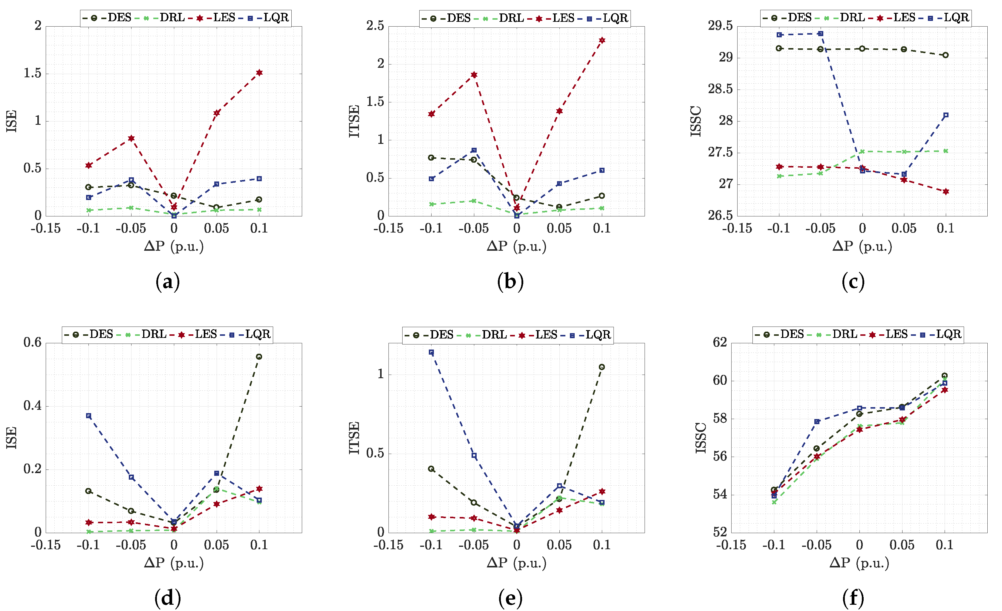
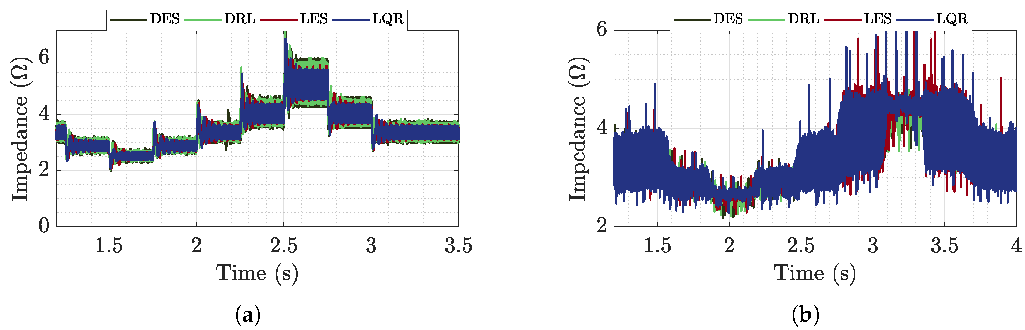
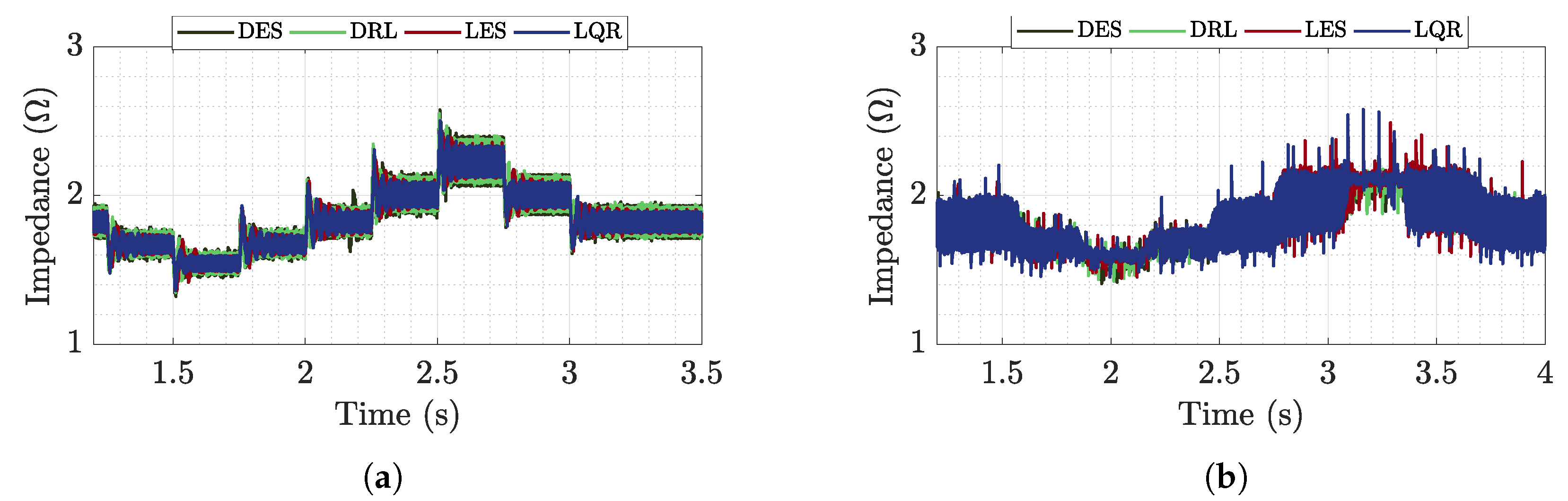
The validation of the CPL buck is shown in
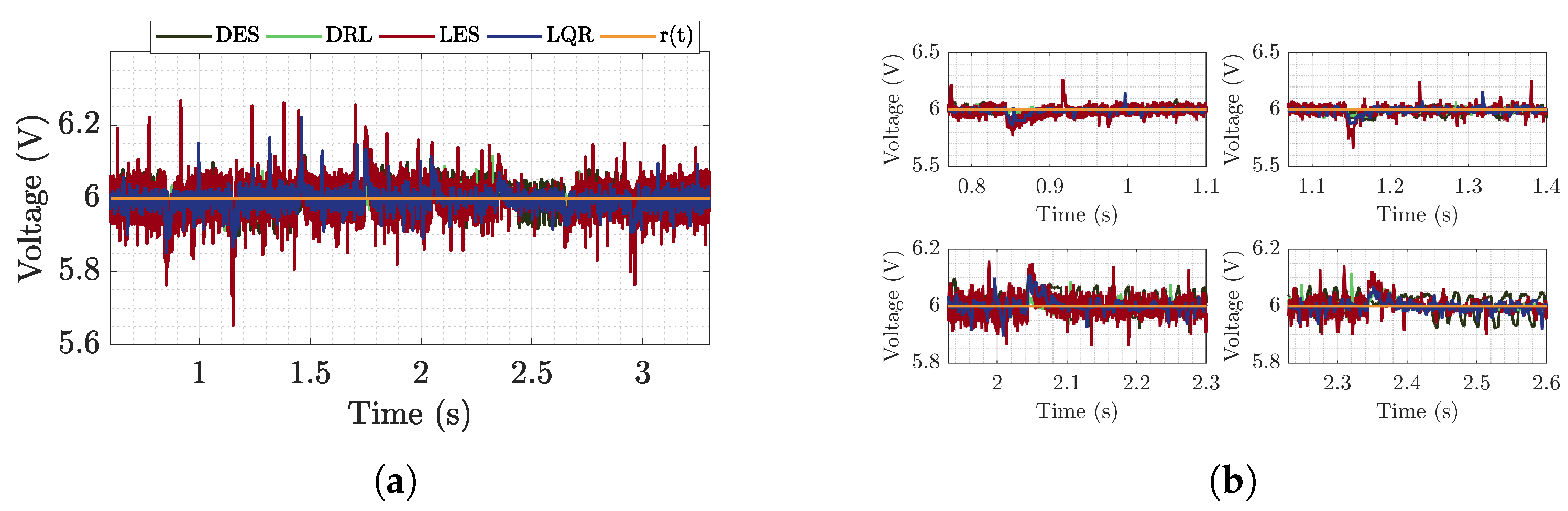
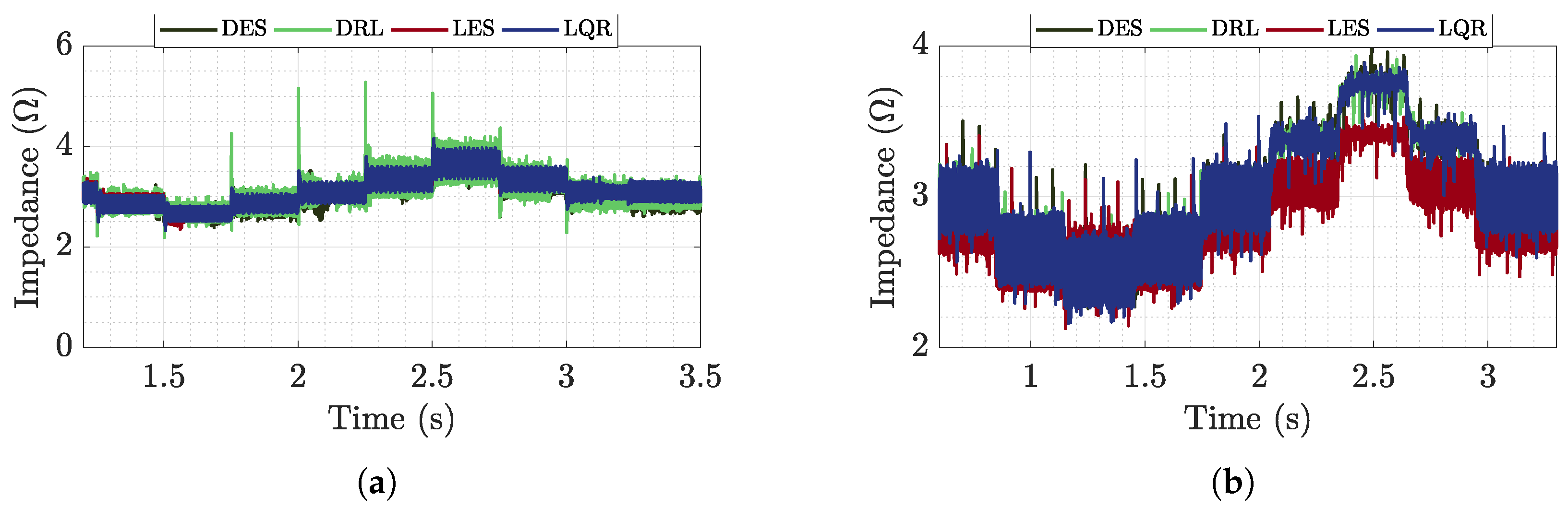
Figure 10, while the validation of the CPL boost is shown in
Figure 11 connected to the DC bus fed by the feeder, for each proposed methodology.
In both situations, the CPLs are validated by simulations and tests. The power variation applied to the boost converter is less than that of the buck converter due to the greater complexity of the boost converter (i.e., non-minimum-phase dynamics due to zero in the right semi-plane), which provides a higher current variation than the buck converter. The results indicate that both converters are able to operate as CPL, since the proposed performance requirements are met.

 ,
, 


