1. Introduction
Real-time simulation based monitoring of physical systems through digital twins is getting more attention due to the ever-increasing computational power of modern processors [
1,
2]. The term “digital twin” holds many definitions, each of them being more or less different, but it is commonly known as a set of accurate models capable of representing a physical system throughout all of its life cycle, from design phase to operation [
3,
4]. Real-time monitoring with a digital twin fed with sensor data coming from the actual system has many benefits, such as fault detection, output optimization and downtime planning. The challenge lies in developing accurate multi-physical models able to interact between each others.
For electrical machines, the core model is the electromagnetic model, which computes electrical quantities such as currents, voltages and electromagnetic torque. As of now, dq models are used extensively for real-time simulation due to their relative simplicity and small computation time, mainly for hardware-in-the-loop testing purpose [
5] and grid simulation [
6]. A computationally efficient model is needed because real-time constraints impose that the simulation time step be larger than the computation time it takes in real-world clock [
7]. However, dq models are based on numerous assumptions; phenomenons like space harmonics or magnetic imbalances are neglected. Furthermore, they only provide information about the quantities seen at the machine terminals.
That said, the only way to obtain a high order model capable of representing accurately any machine structure and computing local quantities as magnetic densities and current densities is by using the well-known finite element method (FEM). It computes locally the Maxwell’s equation solution for any given machine geometry considering even local magnetic saturation. The downside of this technique is the enormous computation time it takes for magnetodynamic resolution which make it challenging for real-time implementation.
Several detailed models of electrical machines have been developed as an alternative to FEM in an effort to make compromises between accuracy and computational requirement for implementation on real-time simulators [
8]. Among these, magnetic equivalent circuits (MEC) models and lumped circuit models using winding functions are the most prominent.
MEC [
9] is a model based on a network of flux tubes capable of representing the unique geometry and winding distribution of a machine. In [
10], an induction motor was implemented for real-time execution on a high clock speed FPGA with a time step of 500
s. A time step of 150
s is attained in [
11] for a switched reluctance motor. While adaquate accuracy can be achieved at a fraction of the time required by FEM, the amount of calculations required in one time step remains high.
On another hand, lumped circuit models using winding function calculations [
12] were also implemented for real-time. In [
13], a synchronous machine model was implemented at 20
s time step using a CPU-based real-time digital simulator. These models considers the geometry of the machine to a certain extent only, because simplifications are made to make analytical calculations manageable and efficient.
However, it was demonstrated in [
14] that, by using a magnetically coupled circuit approach using precomputed inductance functions with a FEM software, it is possible to reach relatively small computation times while keeping the accuracy of FEM. This model is called CFE-CC—Combination of Finite Element with Coupled Circuits [
15]. It has three major strong points:
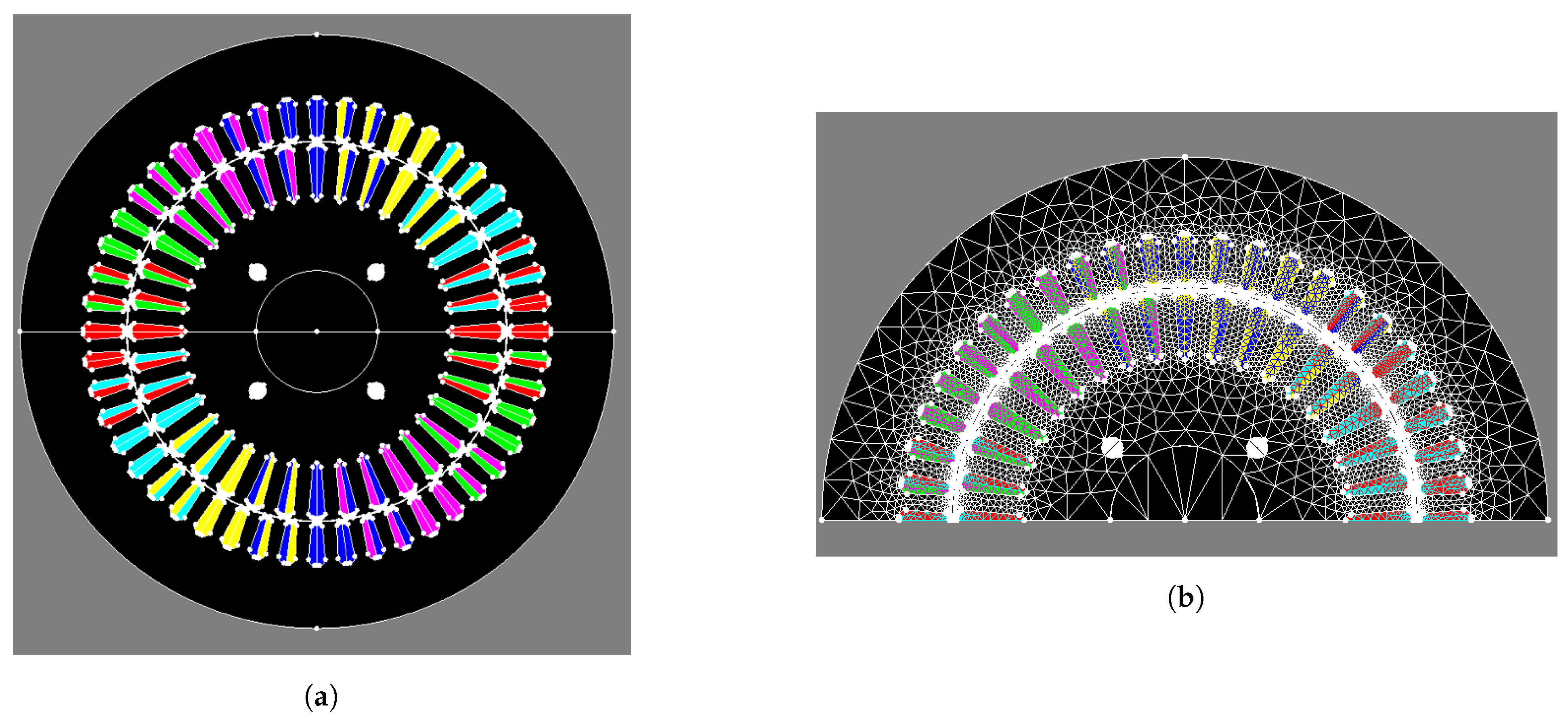
It considers space harmonics and magnetic imbalances since any machine geometry can be modeled in a FEM software;
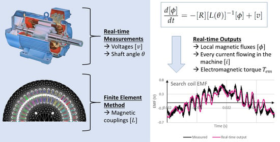
Any number of electrical circuits can be added to the models, including phase windings of course, but also bars, dampers and even search coils. This means the model can output actual currents flowing in bars and dampers and also local magnetic fluxes by using search coils.
It can compute distribution of power losses inside the machine [
16], allowing calculations of local temperature elevation if used with a thermal model [
17].
For these reasons, the CFE-CC model is very close to its physical counterpart. All it takes for building it is the FEM model, which is available from the design phase.
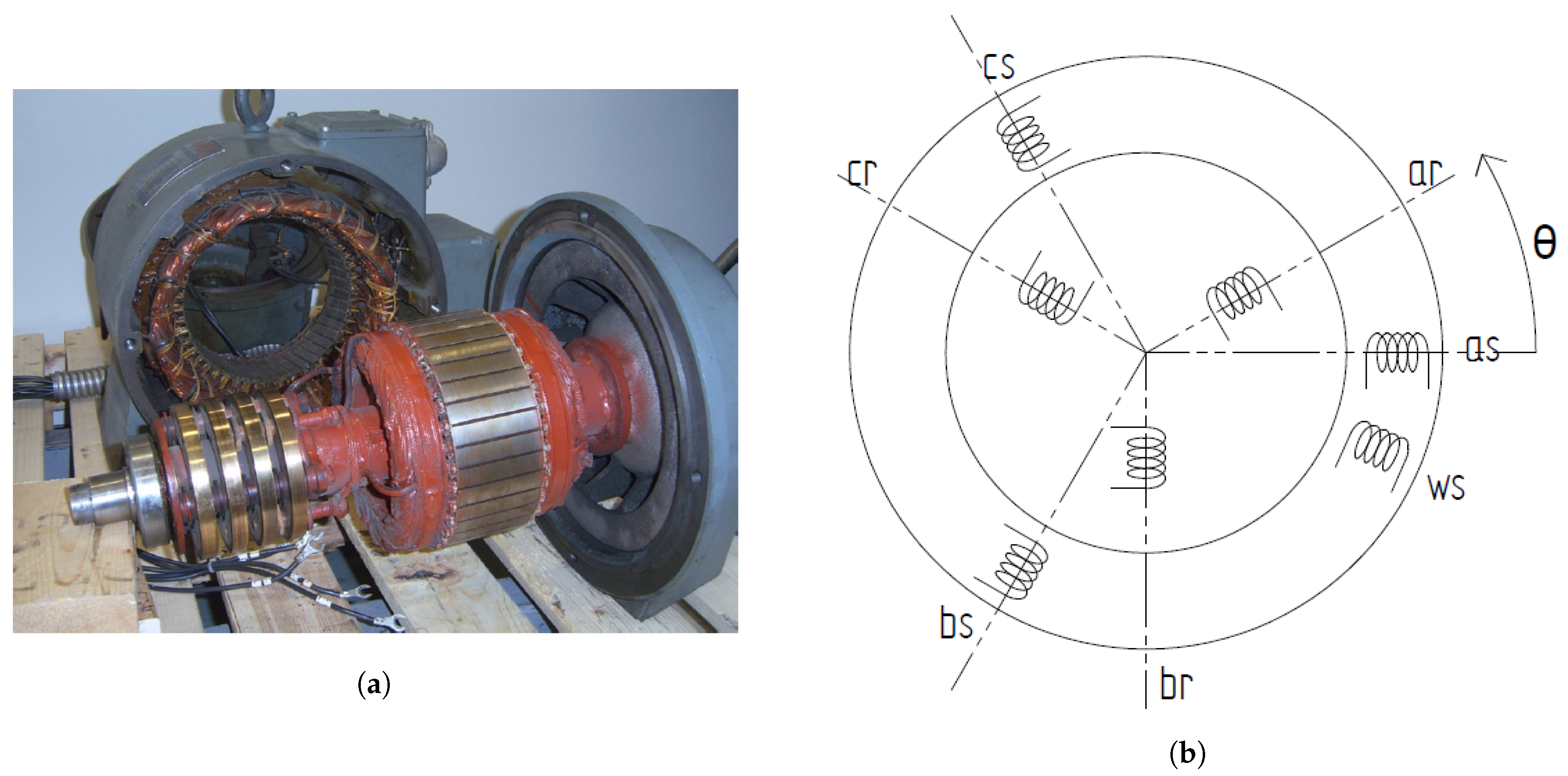
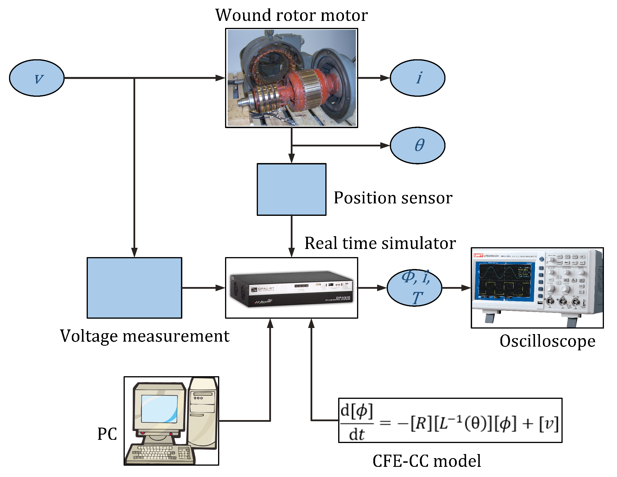
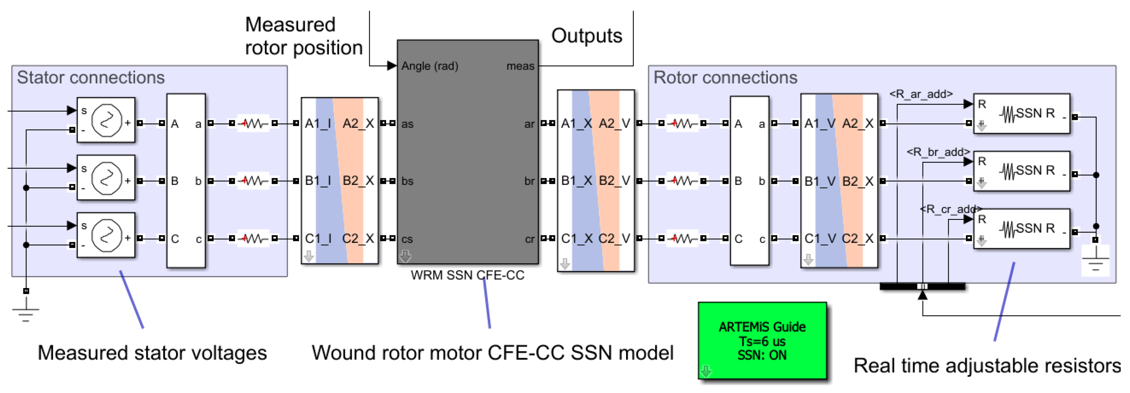
This work presents the methodology to implement for real-time execution the CFE-CC model fed with measurements taken from the real machine, thus allowing effective online monitoring of internal electromagnetic quantities. The proposed electromagnetic model can then be used alongside thermal and mechanical models to complement this real-time digital twin (RTDT). The machine used as case-study to realize the proposed RTDT is a wound rotor induction machine (WRIM), also known as doubly-fed induction machine. This particular type of machine was chosen because all of its electrical circuits are accessible for measurements, thus making it convenient for signal waveform validation. It is important to note however that the described method herein is applicable to every type of electrical machine. After a detailed explanation on the model’s construction and implementation on digital real-time simulator (DRTS), results are validated by comparing in real-time the RTDT’s outputs to the physical machine’s measurements.
5. Validation
Validation of the RTDT was performed by comparing its real-time outputs to measurements available on the physical WRIM during operation. Waveforms shown below are real-time raw data acquired by an oscilloscope. For comparison purpose, a dq model of the WRIM was also implemented on another core of the DRTS for parallel execution alongside the CFE-CC model.
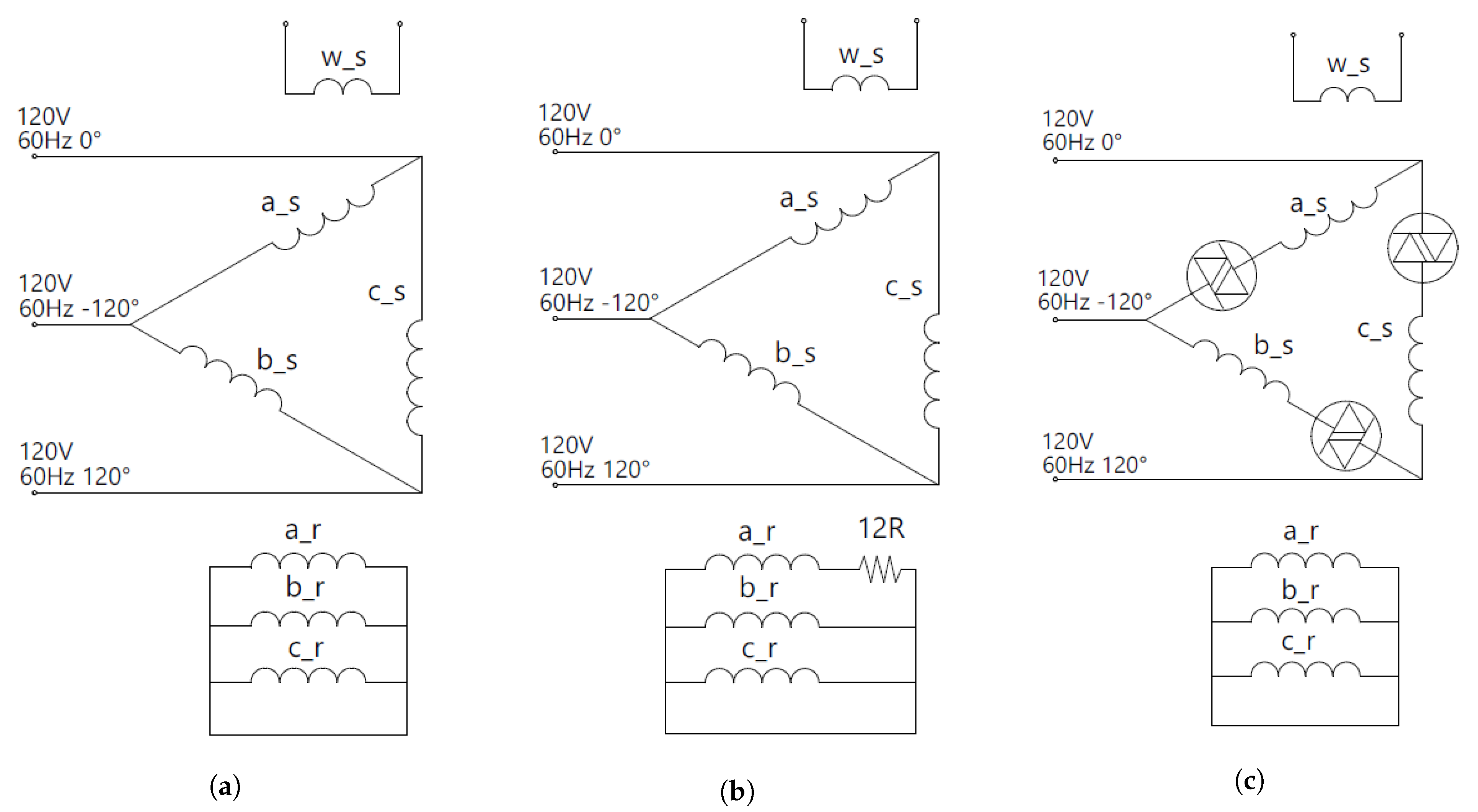
For the first setup, shown in
Figure 6a, the WRIM’s stator windings were connected to a three-phase 60 Hz autotransformer. It was used as an induction motor, so rotor terminals were short-circuited. The WRIM was mechanically coupled to a synchronous generator loaded by resistors.
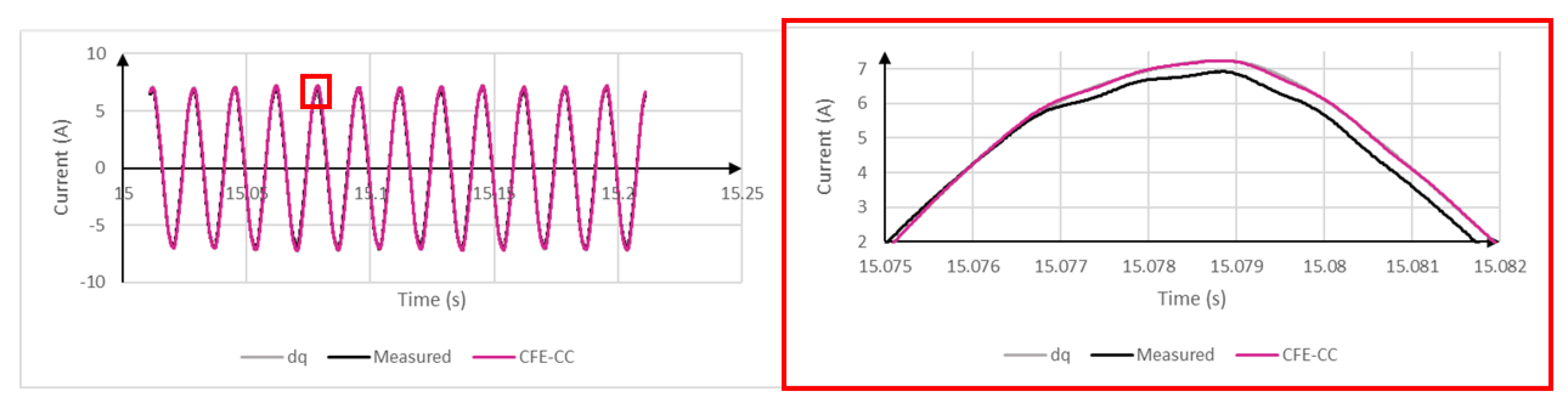
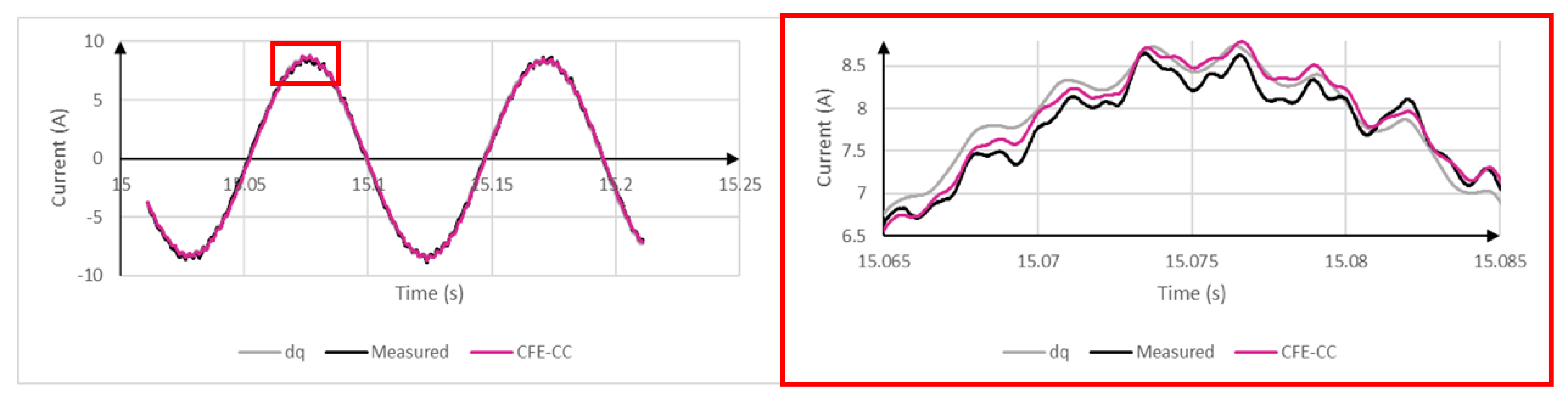
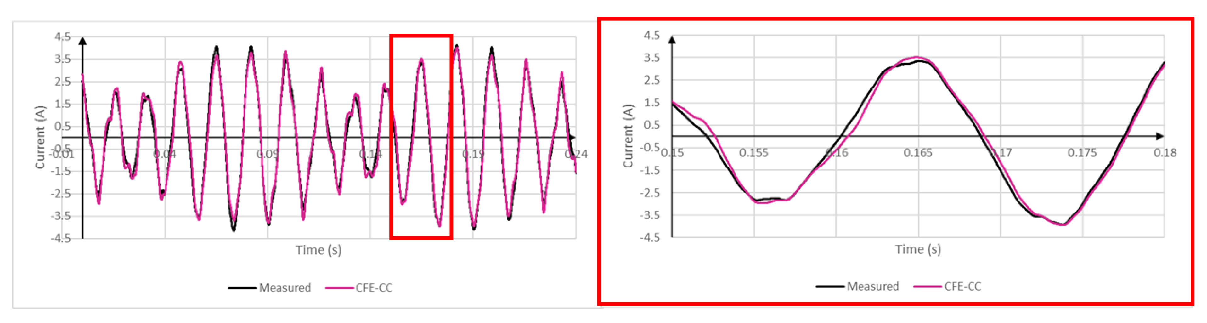
Figure 7 and
Figure 8 show waveform comparisons between measurements, CFE-CC model and dq model. Only winding
a is shown because
b and
c were only 120
phase-shifted. Both models yielded good accuracy, but it was possible to draw more conclusions from the frequency decomposition.
Table 3,
Table 4 and
Table 5 show the notables frequencies of the spectra. As expected, the CFE-CC model approximated well higher frequencies which were related to the geometry of the machine, whereas the dq model only computed harmonics related to input voltage.
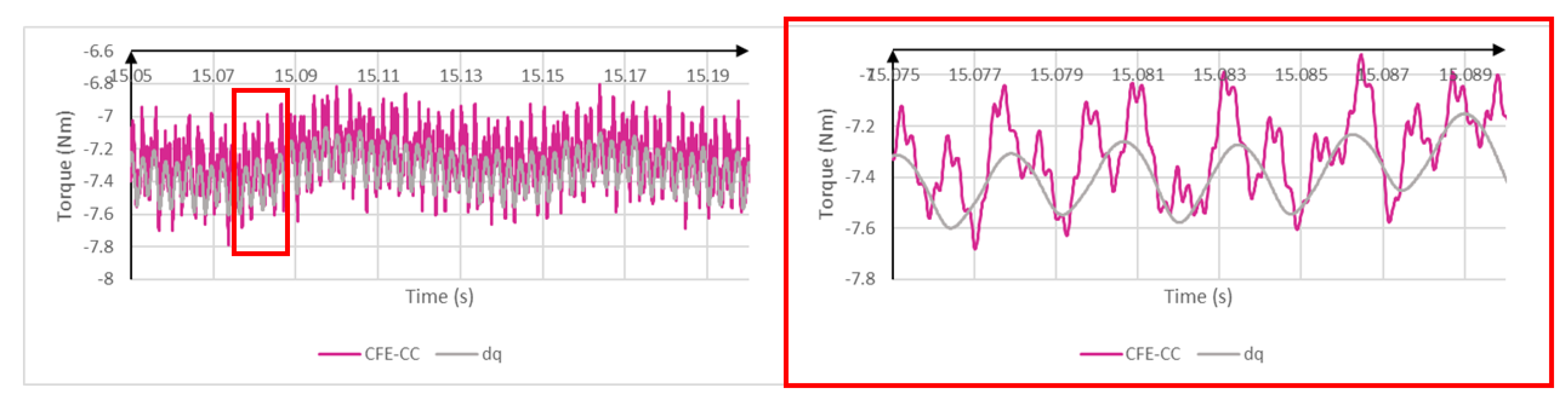
Geometric irregularities of the machine had an impact on the torque as well, as seen from
Figure 9. By analysing the electromagnetic torque of a machine, one can draw many conclusions about its condition.
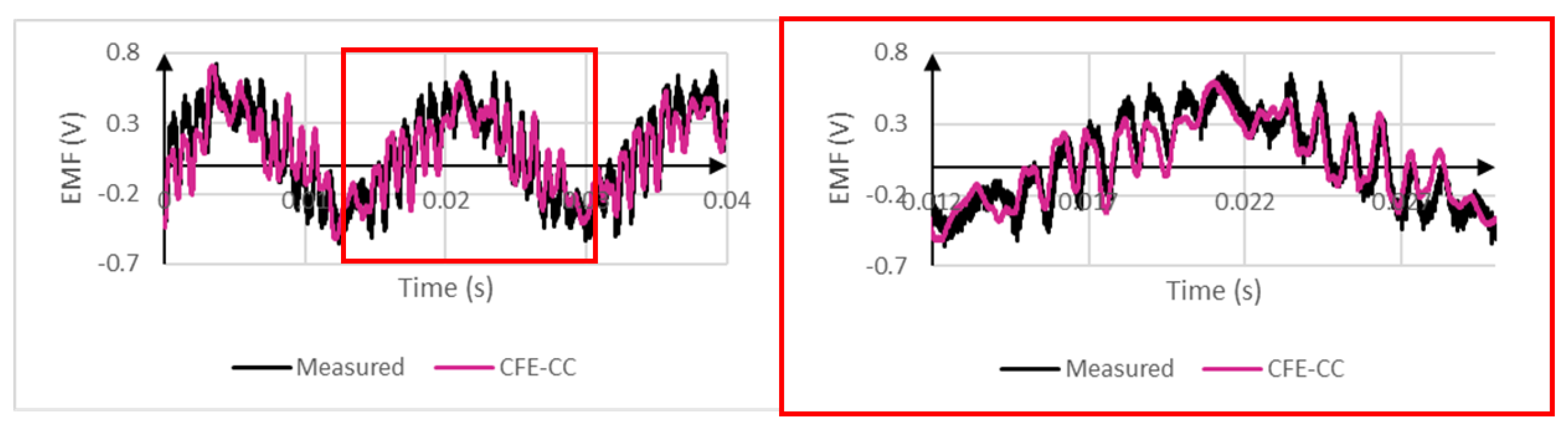
Figure 10 shows the clear congruence between real-time output of the search coil voltage and its measured counterpart. Search coil voltage gave a good indication of local magnetic flux linkage. Using Equation (
11), any number of search coils could be directly added to the machine’s winding configuration without restarting the FEM process. This also proved to be an interesting tool for online fault monitoring.
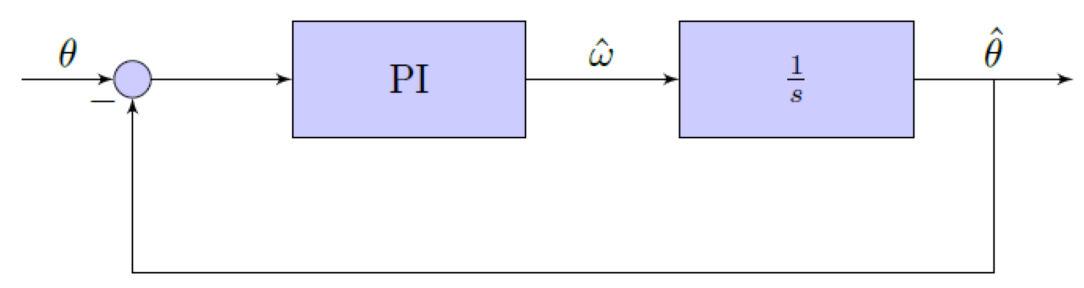
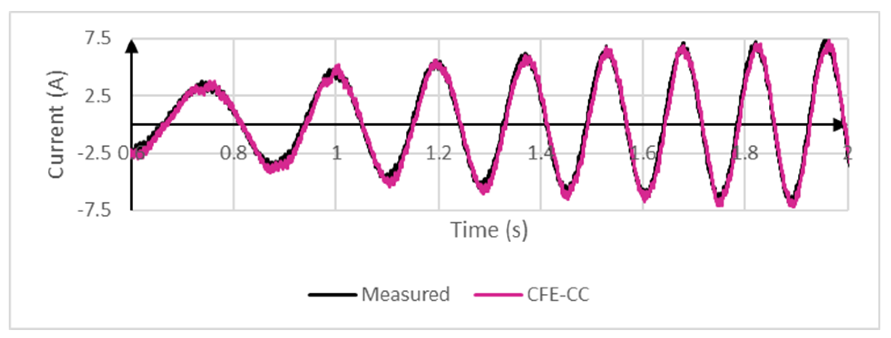
Figure 11 shows the dynamic response of rotor currents when the mechanical load was suddenly disconnected from the shaft. Here, the position tracking control loop played an important role. It needed to be fast enough to minimize the error during speed variations.
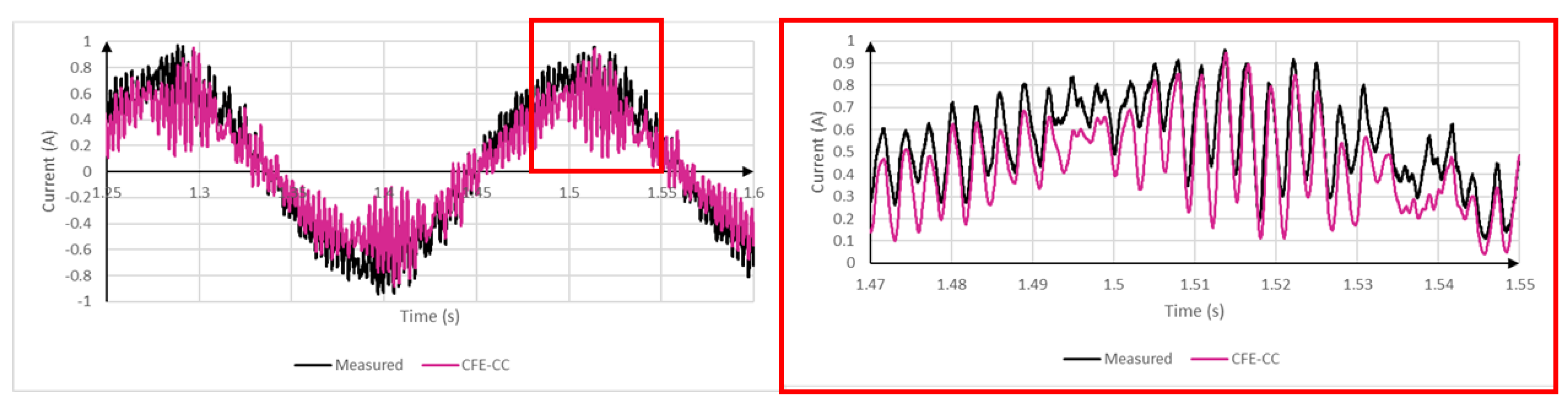
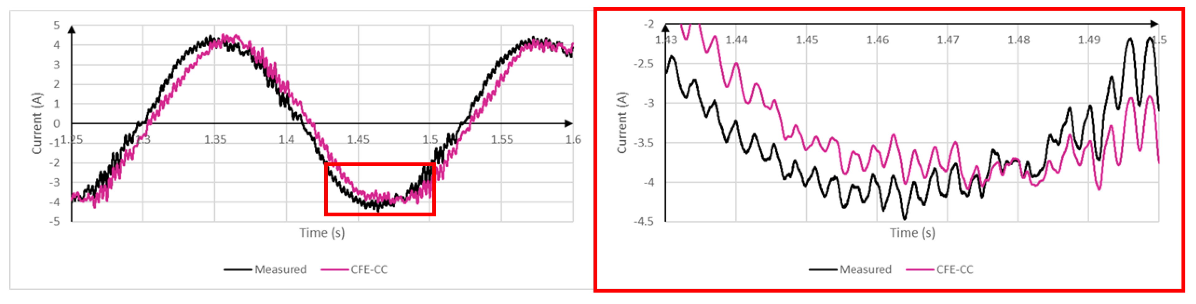
The following
Figure 12,
Figure 13 and
Figure 14 show the RTDT’s current outputs when a phase imbalance was introduced. The setup is depicted at
Figure 6b. A resistor was connected to winding
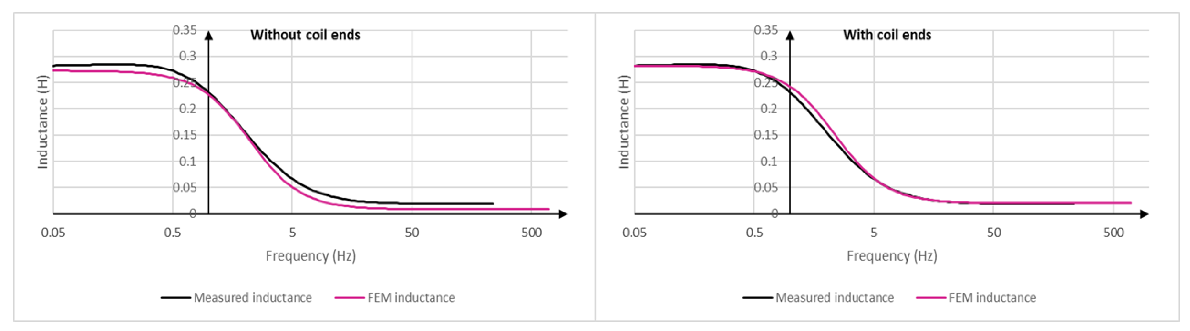
of the physical machine, and the same was done to the RTDT. While the frequency content was accurate, a small phase discrepancy was present at winding
and
. The cause could be related to the methodology employed to compute
in
Appendix A, such as the way the coil end inductances were added. Many assumptions were made. Magnetic saturation could also play a role since it was not taken into account in the model.
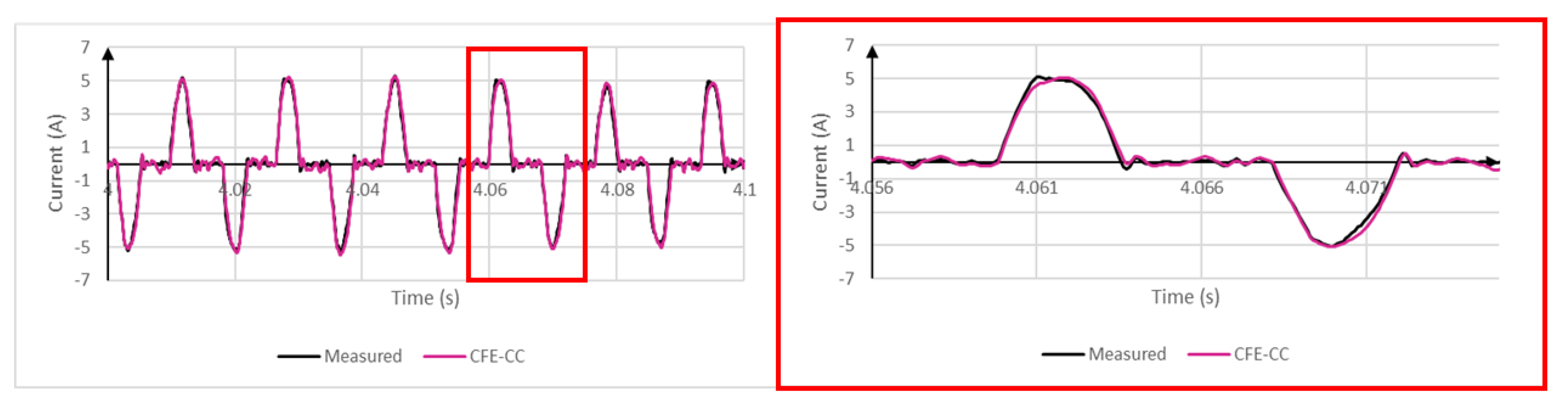
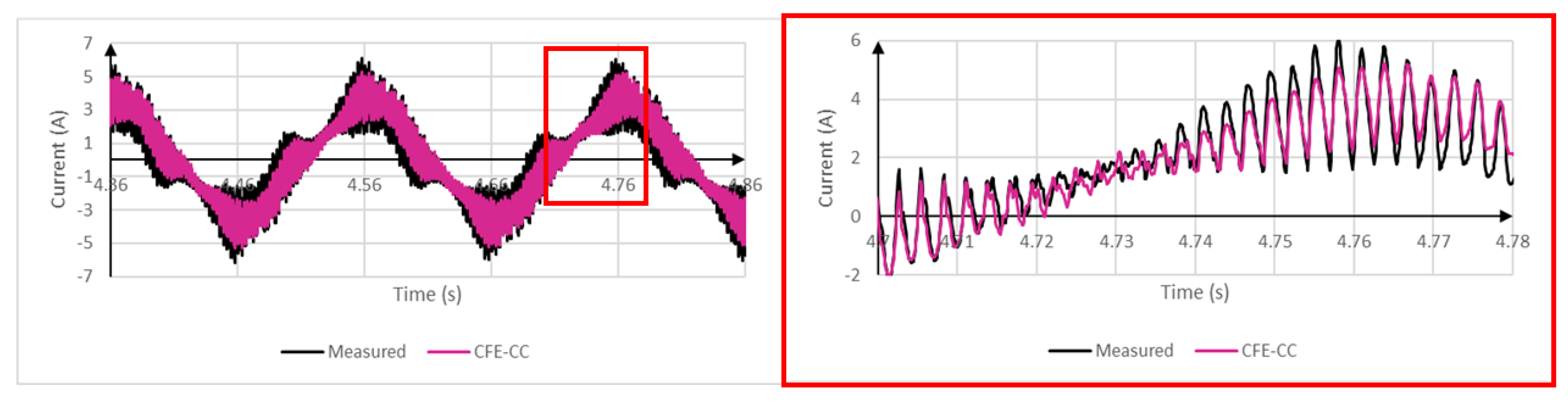
Finally, TRIACs were added inside the delta configuration as depicted in
Figure 6c. It demonstrated the RTDT’s behavior under switching converter’s voltage input for an unusual phase configuration.
Figure 15 and
Figure 16 show currents flowing in windings
and
. The RTDT yielded accurate estimations.


