1. Introduction
This paper is a continuation of the research presented in [
1] regarding the application of magnetic core saturation effects in induction motor diagnosis. In that paper, research on the application of the zero-sequence voltage component (ZSV) in the detection of rotor cage faults and eccentricity was undertaken. This method can be applied to star connected induction motors. The conducted research and analyses proved that the ZSV-based machine diagnosis approach is effective. To complete this study, similar considerations regarding zero-sequence current component (ZSC) applications in motor fault detection were undertaken. This can be applied to delta connected motors and the star connected motors with neutral connection, though this second connection is not practiced in the industry. The motor operating with the zero sequence current has a slightly lower efficiency. This was examined in detail in [
2,
3].
Over the years, many papers concerning ZSC applications in motor diagnostics have been published. In the paper [
4], a simplified model illustrating the interaction of the stator magnetomotive force and the air-gap permeance function is presented. On the basis of this model, the expected spectrum of the zero sequence current for some damages was defined. Conclusions from this analysis indicated further investigations using finite element method and laboratory tests [
5,
6,
7,
8]. More detailed method using a multiharmonic mathematical model of induction motors was presented in [
9]. Inductances of this model depend on the magnetic permeance function comprising effects of magnetic circuit saturation and slotting of stator and rotor cores. So, this mathematical model simulates operation of the whole machine in the considered range. Such modeling method was the background for determining spectrum of ZSV and ZSC characteristic for damages of the cage and three types of eccentric rotor position: static, dynamic, and mixed. This was applied in [
10], but without influence of the machine core slotting, and was used in the mentioned paper [
1]. In the presented paper the methodology of analysis is similar as applied in [
1] but concerns ZSC spectrum used for diagnosis of damages. The zero-sequence current component is a signal that carries a lot of information about a machine’s symmetry. This signal as a sum of all three-phase currents is very vulnerable to internal asymmetries (machine faults) and external asymmetries (an asymmetric supply source), hence it is a perfect signal for validating the machine’s state during manufacturing. Additionally, the zero-sequence current component was used not only for machine diagnosis, but it was used in fault detection for a converter [
11] or its control algorithm.
When analyzing the zero-sequence current, it is worth mentioning the zero-sequence voltage component [
1,
10,
12,
13,
14,
15], the spectrum of which has the same qualities as the zero-sequence current component [
10]. In ZSV and ZSC signals, the dominant harmonic is the harmonic of the frequency equal to triple the supply frequency originating from magnetic core saturation. Consideration of this effect in mathematical models is crucial in terms of the spectral analysis of signals, as it extends the set of characteristic frequencies for a specified type of fault [
9,
10].
The most commonly used diagnosis method is the motor current signature analysis (MCSA), which is based on spectrum analysis of the stator current in the steady state. This can be successfully combined with other stator-current-based methods used to diagnose the rotor cage faults [
16,
17,
18,
19,
20], rotor eccentricity [
17,
21,
22,
23], bearing faults [
17,
22,
24] and stator winding short circuits [
25,
26]. The basic advantage of this method is that it is very easy to perform stator current measurements. This can be done directly by connecting measuring clamps to power supply wires or to secondary windings of current transformers located in control cabinets. When measuring three supply currents—or in the case of a wye stator winding configuration without a neutral wire, only two—symmetrical-component-based spectral analysis methods can be used. Such a transformation of the currents puts in order the harmonics, simplifying the identification of the machine’s faults [
27,
28,
29]. A motor fault detection manner similar to that used in stator-current-based diagnostic methods is also used for motor condition assessment based on axial flux or leakage flux spectral analysis. Measurement of these fluxes is carried out using a dedicated coreless coil wound on the machine’s frame. The measurement coil can be situated on the motor’s housing rear cap side, centrally to its axis, or against the machine’s housing. Based on the current spectrum, it is possible to diagnose rotor cage faults [
30,
31,
32,
33,
34], eccentricity [
23,
35,
36], bearing faults [
35,
37], or the occurrence of winding short circuits [
31,
36]. Undoubtedly, the advantage of this method is that it allows contactless measurement and does not require any interference in the circuit, which in industrial conditions simplifies the measurement process.
Machine failure-related downtime generates not only repair costs but also costs related to industrial processes being stopped, hence hybrid methods [
16] that consider more than one signal for condition diagnosis are becoming more popular. The current state of the art and a description of the methods used in electric machine diagnosis can be found in [
38,
39,
40]. Induction machine diagnosis methods are constantly being developed due to the need for constant monitoring of machine conditions. Deep learning with smart sensors and artificial intelligence is constantly gaining popularity. A description of the used algorithms and a review of publications in this research field can be found in [
41]. At this point, it can be noticed that it is difficult to protect the motor from short-circuits in the stator winding with the use of spectrum measurement methods, because the operation of detecting and switching off the motor must take place before the end of the start-up. It is the subject of separate considerations with the use of artificial intelligence [
42].
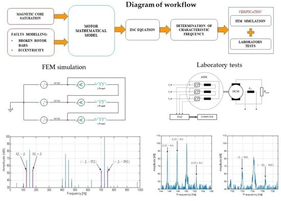
The studies presented in this paper start from analysis of the mathematical model of the squirrel cage induction motor in order to determine the characteristic spectrum of ZSC for the considered failures, despite the fact that the model formulated in this way has the necessary simplifications. This is presented in
Section 2,
Section 3 and
Section 4. In
Section 2, the definition of the zero-sequence current component and its measurement methods for various winding configurations are presented.
Section 3 contains crucial assumptions concerning inductance, especially the permeance model, which includes magnetic core saturation and eccentric situation of the rotor. In
Section 4, the mathematical model of the motor and mathematical analysis of the zero-sequence current component equation are presented. The influence of the winding configuration on ZSC is also studied.
Section 5 contains a finite element model of the motor and simulation results for the following cases: symmetry; rotor cage faults; static, dynamic, and mixed (superimposed static and dynamic) eccentricities. Short circuit detection of stator winding turns with the ZSC spectrum was not analyzed in this paper.
In
Section 6, laboratory tests and its results are described.
Section 7 contains discussion of the obtained results. Conclusions are developed in
Section 8.
Most of the considered machine failure cases can be diagnosed by other methods discussed in the cited literature, in particular by examining the stator current spectrum (MCSA). However, the use of the stator current zero sequence measurement (ZSC) allows for an unambiguous determination of mixed eccentricity.
2. Application of ZSC Induction Machine Fault Detection
The zero-sequence current component (ZSC)
descends from the power invariant transformation to symmetrical components
where
,
are stator phase currents and
are the stator current positive and negative symmetrical components, respectively.
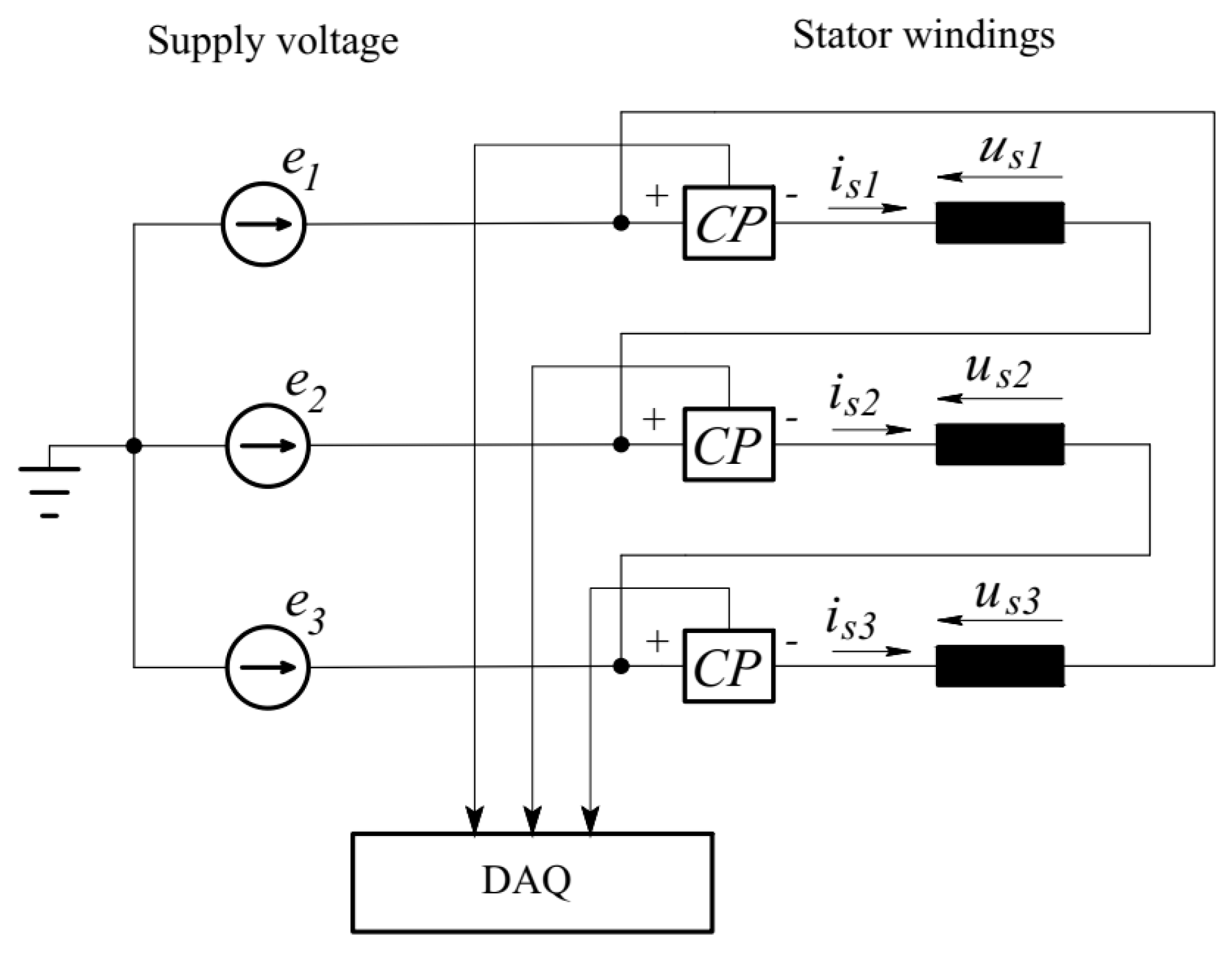
The ZSC measurement system in the case of a delta stator winding connection is shown in
Figure 1.
When the stator winding is delta-connected (
Figure 1), the zero-sequence voltage component
, since
In case of a wye configuration with the neutral wire, there is no need to measure each phase current separately. It is sufficient to measure the neutral wire current
in shown in
Figure 2.
Then, the zero-sequence current component can be calculated from the formula
where:
Stator-phase-induced voltages are equal to phase supply voltages (at the zero impedance of the neutral wire):
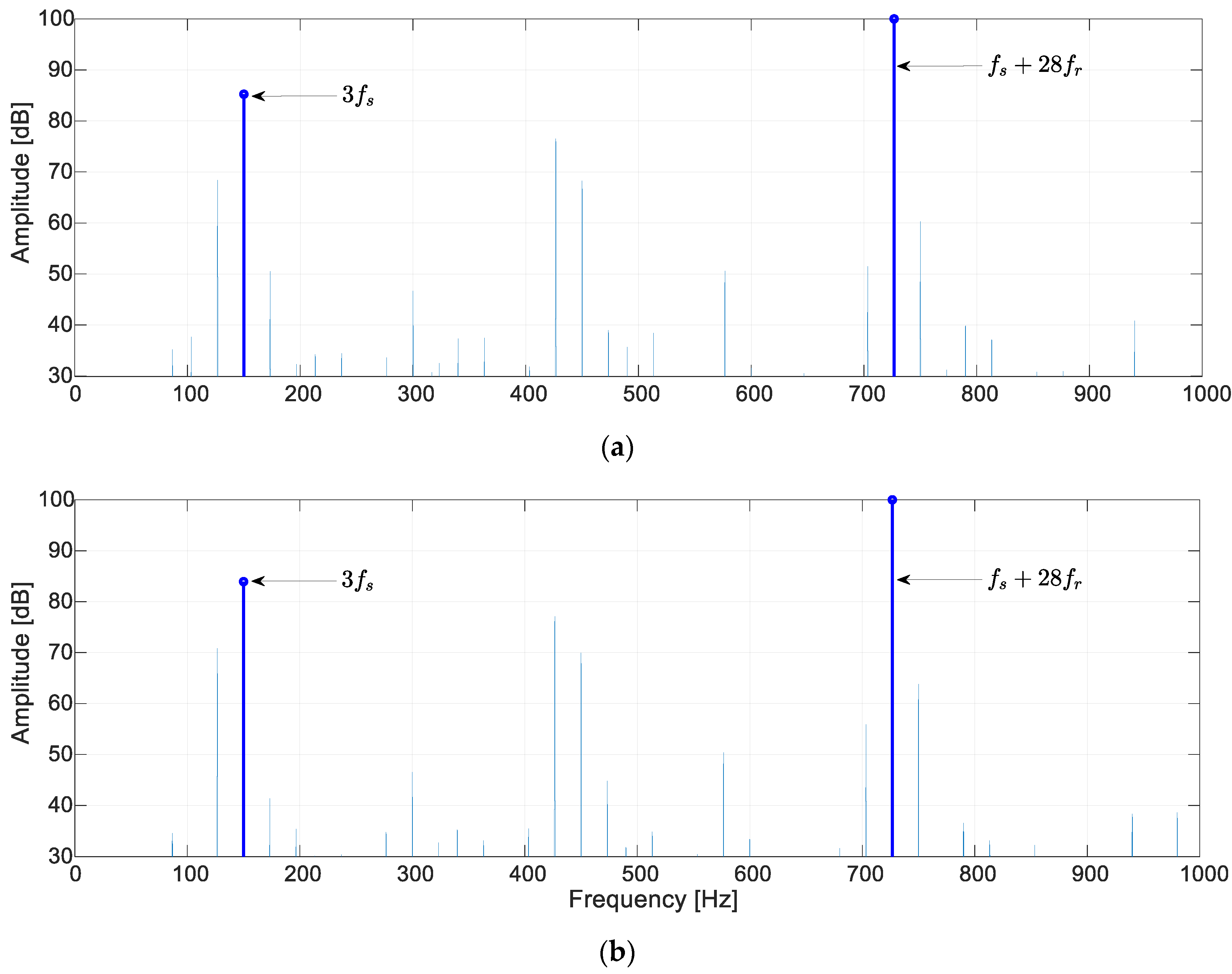
During the preliminary analysis of ZSC for three selected cases, namely symmetry, rotor cage fault, and mixed eccentricity cases, similarities to the zero-sequence voltage component (ZSV) were observed in the spectra [
1]. Since ZSC component depends on the ZSV component, it is vulnerable to any asymmetries related to the machine’s faults. An exemplary comparison of the spectra determined due to finite element modeling (FEM) for the asymmetry cases mentioned above is presented in
Figure 3 for induction motor with 2 pole pairs, 36 stator slots and 28 rotor cage bars.
One can see that the core saturation-related harmonic of the frequency equal to the triple supply frequency is dominant in both ZSV and ZSC signals [
10]. Including this phenomenon in further considerations will allow the mechanism of the origination of the new harmonics related to the machine’s faults to be explained.
To avoid noise interference in the measured signals, they are transmitted using shielded cables. Nevertheless, a certain level of noise is observed in the measured signals. However, the useful signal exists above the noise and can therefore be cut off easily.
3. Inductance Model
For zero-sequence current component spectrum interpretation, a poly-harmonic mathematical model of a cage induction machine is used, which was developed and is described in detail in [
1,
10]. The most important assumptions of the model will be presented in this paper.
The model is based on the per-unit permeance function, defined as [
9]:
which models the magnetic permeability variation caused by core saturation. This function depends on the amplitude
and the electrical angle
of the magnetizing current vector where
is the angular position with reference to the stator,
-pole pair number. For satisfactory approximation, it is enough to limit the set of harmonics to a constant component and the first alternating component of the series
. This manipulation is intentional, since it includes only the strongest effects related to saturation effects.
Another factor influencing the magnetic permeability is the variable air gap length caused by the rotor eccentricity. One can distinguish three types of eccentricity: static, dynamic, and mixed. The per-unit function that models this phenomenon can be derived based on geometrical dependencies and is written in the form of a Fourier series [
43]:
where
is an average air gap length considering the slot opening geometry with the Carter’s factor of a healthy motor,
is the air gap length variation function,
is the angle coordinate,
is the rotor rotation angle,
. Depending on the type of eccentricity, function (8) takes one of the forms presented in
Table 1.
The final form of the magnetic permeance function is the result of amplitude modulation of the so-called base permeance:
where
is an average air gap length considering the slot opening geometry of a healthy motor. The modulating function models the influence of the magnetic core non-linearity (7) and rotor eccentricity (8):
where:
The permeance function (10) models the influence of magnetic saturation and rotor eccentricity, but it neglects air gap length variation caused by the slotting of the stator and rotor. From the mathematical point of view, this function models a non-uniform air gap. Thus, the mutual inductance of the two windings “a” and “b” can be described using the relationships presented in [
44,
45,
46,
47]. For function (10), the mutual inductance takes the form:
In the above, are the number of phase winding turns; are winding factors for harmonics orders and ; p is the stator pole pair number; is the magnetic permeability of the vacuum; is the stator inner radius; is the length of the magnetic core; and z is the axial coordinate. For stator windings “a” and “b”, . For rotor cage meshes, . The stator windings “a” and “b” generate a magnetic field, and the distribution can be approximated by the Fourier series of orders or . For winding “a”, ; whereas for winding “b”, . The currents flowing in the symmetric rotor cage of N bars generate a magnetic field, the distribution of which is approximated by the Fourier series of the harmonic numbers for winding “a” and for winding “b”.
Coefficient
in (13) determines the existence of inductance. It is expressed in the form:
leading to the fundamental dependence between harmonic orders
belonging to the defined sets of harmonic orders
,
, and
. These sets determine the harmonic accuracy of the model.
4. Mathematical Model of a Cage Induction Motor
Based on inductance Formula (13), mathematical model was derived and next transformed from the machine variables to symmetrical components [
9,
10]:
The most important are the inductance matrices containing elements for the determined harmonics in each cell. The stator self-inductance matrix
has the form [
1]:
where:
where
X is the row number {0,1,2} and
Y is the column number {0,1,2} corresponding to symmetrical components of the stator current vector
.
The stator–rotor mutual inductance matrix
has the form [
1]:
where:
where
X is the row number {0,1,2} and
Y is the column number
. corresponding to symmetrical component of the rotor current vector
.
Considering (18) and (20), one can determine the inductance form in each cell of the inductance matrix. This property will be used while determining characteristic frequencies for ZSC spectrum interpretation.
Thus, the formula for the zero-sequence voltage component can be derived [
1]:
where
,
,
,
,
is the stator winding resistance and leakage inductance,
. The Formula (21) is written in the general form without considering the winding configuration, which is crucial in further analysis. This can be refactored to the form
Where
In the case of a wye connection without neutral point connected, the zero-sequence current component
is equal to zero by definition, and only the zero-sequence voltage component
can be subjected to further analysis, as was done in [
1,
9,
10]. Equation (22) might then be defined as
The zero-sequence current component (ZSC) occurs in two stator winding configurations: (a) the delta connection, shown in
Figure 1; (b) the wye connection with the neutral wire, shown in
Figure 2. Each of these configurations has its own properties. For the delta connection, the sum of the phase voltages is equal to zero, hence Equation (22) takes the form:
which can be represented in
Figure 4 as the equivalent circuit.
In the case of the stator winding wye connection with the neutral wire, the sum of the phase voltages is equal to
according to (6). Transforming (6) to symmetrical components
one obtains
Thus,
leads to the equivalent circuit shown in
Figure 5.
The non-zero voltage source
is present only when the motor is supplied from a three-phase asymmetric voltage source,
. This means that, together with motor asymmetries, it has a direct influence on the zero-sequence current component
. In contrast, the zero-sequence voltage
can be measured separately from the supply voltages, as shown in
Figure 6 [
1].
Equivalent circuits from
Figure 4 and
Figure 5 show that the voltage source
is the main influence on the zero-sequence current
. However, this voltage source is equal to the zero-sequence voltage component
when the stator is wye-connected, as in
Figure 6. Therefore, one can expect that harmonics appearing in the zero-sequence voltage
will occur in the zero-sequence current
, as in
Figure 3. In [
1], the mechanism of harmonic generation in ZSV due to the motor’s faults is described in detail. The characteristic frequencies of the spectra of
and
indicating the machine faults are presented in
Table 2.
The sets of indicators in
Table 2 determining the sets of harmonic orders are given as follows:
,
,
,
(in case of rotor cage fault),
, where
is the supply frequency,
is the rotational frequency, and
is the motor slip where the maximum values are taken arbitrarily with respect to harmonic accuracy. The orders
and
in
Table 2 must satisfy the condition for inductance existence (15) in the matrix cell
(0-th row,
-th column) [
1]:
The above dependences were applied to the particular case of the induction machine having the pole pair number
and the number of rotor bars set at
. This is the same machine as in [
1], which is now undertaken for continuing analysys of the zero-sequence stator current
properties to diagnose the machine faults. Therefore, following the analysis performed in [
1], the characteristic frequencies of the
spectrum indicating the faults of the induction machine against the background of a healthy motor are shown below.
Healthy motor: .
Static eccentricity: .
Dynamic eccentricity: .
Mixed eccentricity: .
Rotor cage damage: .
The frequencies can be limited to the values below 1 kHz, since this threshold is sufficient to determine the damage of the induction machine. The ZSC signal an easily be decomposed to the components of such a frequency.
5. Finite Element Simulations
The first step in the verification of the frequency reference values obtained above from the mathematical motor model is the finite element analysis. The cage induction motor model was prepared in the Maxwell ANSYS environment for numerical simulations. The model of the machine built in Maxwell 2D software is based on the Sg112M-4 induction motor with the rating:
PN = 4 kW,
UN = 400V (Δ),
IN = 8.7 A,
nN = 1440 rpm,
fN = 50 Hz, cosϕ
N = 0.77, η
N = 86.6%. The single-layer stator winding has
p = 2 pole pairs and is symmetrically distributed in 36 stator slots. The rotor cage has
N = 28 bars. A non-linear M19 steel sheet was used in simulations. Simulations were performed for the two stator winding connections shown in
Figure 7.
The zero-sequence current component spectrum was investigated for the following motor conditions: (1) healthy; (2) static eccentricity 77%; (3) dynamic eccentricity 77%; (4) mixed eccentricity (static 20%, dynamic 20%); (5) one broken bar in the rotor cage. The rotor cage bar fault was modeled by increasing the resistivity of the material 100 times in one bar. Eccentricity modeling was done as follows:
- (a)
Static eccentricity: The axis of rotation was shifted by 0.77δmin mm with respect to the stator’s symmetry axis but aligned with the rotor’s symmetry axis.
- (b)
Dynamic eccentricity: The rotor was shifted by 0.77δmin mm with respect to the stator’s symmetry axis and axis of rotation.
- (c)
Mixed eccentricity: The stator was shifted by 0.2δmin with respect to the axis of rotation and the rotor was shifted by 0.2δmin with respect to the axis of rotation.
The air gap length in the Sg112M-4 model was δmin = 0.3 mm. In all simulations, the rotational speed was constant and equal to 1450 rpm. The rotor skew was not taken into account in the motor model, so it was expected to obtain a spectrum where the harmonic amplitudes of frequencies related to the multiple of the number of rotor bars would be overestimated. The simulation time was set to 10 s with a 0.1 ms step, which allowed us to obtain the ZSC spectrum with a frequency range of up to 5 kHz, with sufficient resolution for proper identification of the harmonics indicated by the mathematical model.
Figure 8,
Figure 9,
Figure 10,
Figure 11 and
Figure 12 below present analyses of the zero-sequence current component obtained from finite element simulations for delta and wye cases with neutral wire winding connections. The spectra were grouped based on the machine’s condition. Only harmonics of amplitudes greater than 30 dB were considered for detailed analysis.
The obtained ZSC time waveforms were put forward for FFT analysis, then characteristic frequencies were marked for certain machine conditions (healthy motor = blue; static eccentricity = green; dynamic eccentricity = red; mixed eccentricity = purple; broken rotor cage = black). Direct comparisons of the spectra around the harmonic of the triple supply frequency for the case of a broken rotor cage bar with the spectrum of a healthy motor are shown in
Figure 13 and
Figure 14.
Each selected frequency characteristic harmonic for a given fault, regardless of the stator winding connection, experienced a significant amplitude increase. The amplitude levels of the harmonics extracted from the spectrum of the healthy motor were below the accepted threshold of 30 dB. Some
Table 3 cells are filled with “-”, which means that the harmonic is not in the signal spectrum. Spectra obtained from the simulation can be treated as a reference, as they are externally distortion-free, and hence are ideal cases. Such a situation does not occur during laboratory tests, especially in industrial conditions. The ZSC spectra for winding configurations of delta and wye connections with neutral wire hardly differed from each other. The amplitudes of selected harmonics respond to a particular fault type in the same manner, which can be observed when analyzing the results contained in
Table 3 and
Table 4.
6. Experimental Tests
Laboratory tests were carried out on the same motor as for the theoretical analysis and for the same stator winding connections. The motor was loaded with the DC generator with a rated power of
PN = 4.5 kW, as presented in
Figure 15. Tests were carried out for the following cases: healthy motor, faulty rotor cage, and eccentrically positioned rotor. A rotor with one cut cage bar was used during the test for rotor asymmetry, whereas for eccentricity a rotor mounted on a misaligned bearing shield was used. These modifications provided 40% static eccentricity and 40% dynamic eccentricity, which resulted in mixed eccentricity. The generator load torque during all measurements was set to obtain a load current equal to 60% of the motor’s rated current.
The current measurement was done using E3N (Chauvin Arnoux) measuring clamps, the output signals of which were sent to a BNC 6259 measuring card from National Instruments. Each measurement was performed with a 10 kHz sampling frequency and 60 s measurement time.
The measurements of the failure states of the induction motor were performed in almost the same conditions as for the simulation using the finite element method. Registered signals were further analyzed with FFT and typical fault harmonics were found and highlighted. The results of the spectral analysis of the motor with eccentricity for both stator winding configurations are shown in
Figure 16 and
Figure 17.
In
Figure 16 and
Figure 17, the amplitudes values of the highlighted harmonics (dynamic eccentricity = red; static eccentricity = green; mixed eccentricity = purple) increased compared to harmonics of the same frequencies occurring in the spectrum of the healthy motor. The amplitude values for both stator winding connections are shown in
Table 5 and
Table 6. Due to different noise levels in the registered signals caused by different measurement circuits as those shown in
Figure 15, we decided to measure the amplitudes of selected harmonics with respect to the noise level of each signal.
The biggest differences between amplitudes of healthy and damaged motors can be observed for the case of mixed eccentricity, especially for harmonics with frequencies of 3
fs −
fr and 3
fs +
fr. These harmonics do not occur in the healthy motor’s spectrum, hence one can state that they indicate the machine’s fault unambiguously. The zeros in
Table 5 and
Table 6 mean that the harmonic amplitude is at the noise level.
The ZSC reacts very strongly to rotor cage asymmetry through increasing the slip harmonic amplitudes around the triple supply frequency and base slot harmonic. The frequency spectra for this case are presented in
Figure 18 and
Figure 19. The amplitudes of the selected harmonics were measured and are shown in
Table 6.
The presented laboratory test results confirmed the possibility of using the zero-sequence current component in effective detection of rotor faults and eccentricity. The ZSC spectra obtained from measurements for different stator winding configurations looked very similar and contained the same harmonics as the ones calculated from the mathematical model. When measuring the ZSC in a motor with a delta-connected stator winding, it is necessary to use identical high-quality current probes (
Figure 15a). Before the measurement, the probes should be calibrated in order to reduce the measurement error. Measuring three currents with non-calibrated or inaccurate current probes would result in improper ZSC calculations, which in turn would result in incorrect fault detection, especially for static eccentricity.
7. Discussion
The detection of induction motor faults based on the stator current zero-sequence spectrum (ZSC) analysis gives almost the same effects as the stator voltage zero-sequence spectrum (ZSV) analysis presented in [
1]. The main benefit of using the current analysis is the ability to diagnose a delta-connected motor.
7.1. Rotor Cage Asymmetry and Dynamic Eccentricity
Rotor cage asymmetry is a type of fault, which is most visible in the ZSC spectrum. It is clearly visible around the triple supply frequency, which was confirmed by finite element simulations and laboratory tests. The formulas derived from the mathematical model points to the same harmonic frequencies for dynamic eccentricity. Dynamic eccentricity harmonics, however, are not as clearly visible in the spectrum as rotor cage fault harmonics, and moreover mixed eccentricity harmonics are often in the vicinity. Based on this, one can distinguish these two types of fault.
7.2. Static Eccentricity
To detect static eccentricity from the ZSC analysis, it is recommended the use of delta-connected stator windings. This allows separation from the supply voltage asymmetry, which generates similar symptoms in the ZSC spectrum [
13] as the static eccentricity. Using the measurement circuit shown in
Figure 15b, for star-connected stator windings, one has to take into account the direct impact of the supply voltage asymmetry on the zero-sequence current component circuit (
Figure 5).
7.3. Mixed Eccentricity
The finite element analysis and the results of the laboratory tests proved that the mixed eccentricity generates new harmonics in the ZSC with respect to the healthy motor. The results clearly indicate this type of fault. This is very helpful in distinguishing dynamic eccentricity from the rotor cage faults. Moreover, harmonics generated by this type of fault are very easy to identify in the frequency spectrum, as they are not generated by other machine’s faults.
7.4. Disadvantages of ZSC-Based Motor Fault Detection
Undoubtedly the important disadvantage of ZSC-based motor fault detection is the measurement method where three current sensors are required. With the delta-connected stator winding in industrial conditions, in most cases one does not have access to phase wires, only to power supply wires. In this situation, it is impossible to connect current probes to phase wires, or this requires some interference in the machine’s structure, which may be prohibited for safety reasons. The exceptions are medium-large induction motors with star-delta starters, where in switchboards there is access to the phase conductors connecting phase windings.
On the other hand, winding connections in the wye configuration with neutral wires are not used in the industry. Motors equipped with residual current circuit breakers with the star neutral point being grounded might be the exception. In this situation, one can use a protection circuit and connect to its wire only if it is available in the control cabinet.
8. Conclusions
This paper presents research on the application of the ZSC in cage induction motor fault detection. It was proven that harmonics occurring in the ZSV spectrum [
1] are also present in ZSC spectrum for the same fault type. The chosen permeance model, which includes a magnetic core saturation effect, can obtain a bigger set of characteristic frequencies for a specific type of fault.
The finite element analysis and laboratory test results proved that the ZSC spectra for the motor with delta and wye winding configurations looked similar and contained the same harmonics. Slight differences resulted from ZSC measurement circuits for both types of winding connections, which can be used to distinguish the machine’s inner asymmetry from the supply voltage asymmetry as the diagrams in
Figure 4 and
Figure 5 show.
More than one failure may occur during operation of an induction motor, e.g., broken cage bars cause a one-sided magnetic pull which can cause bearing degradation and eccentric rotor position. The rotor cage asymmetry can be easily detected due to the presence of: , , and in the ZSC spectrum. If, however, an additional mixed eccentricity appeared, the additional frequencies and would allow to detect it. In practice, this type of eccentricity is almost always present, and there is rarely pure static or dynamic eccentricity.
The effectiveness of the presented diagnostic method will be tested when the induction motor is powered by a frequency converter, e.g., a voltage source inverter, or another converter, e.g., a soft starter. The influence of the deformation of the line currents on the zero sequence current is relatively small, and therefore effective diagnosis can be expected. However, the influence of the automatic control system should be considered, e.g., scalar control, field-oriented control, direct torque control, etc.


