1. Introduction
In recent years, the aerodynamic drag performance of an automobile has become more important for its fuel efficiency because the efficiency of the powertrain has rapidly been improved through hybridization, electrification, and the improvement of combustion technology. In the conventional development process of vehicle aerodynamics, a vehicle subjected to a steady and uniform airflow in a wind tunnel or numerical simulation has been considered. This condition assumes a relative airflow acting on a vehicle running at a constant speed and a steady posture in stationary air. Additionally, the changes in the relative wind direction caused by on-road disturbance and their effects have been investigated using the so-called yaw condition or steady crosswind method [
1], in which a real automobile [
2] or an experimental vehicle model [
3,
4,
5] is placed at a steady yaw angle with respect to a uniform flow. However, the impact of more realistic on-road disturbances on automobile aerodynamics has attracted attention to further increase the accuracy when evaluating the aerodynamic performance of an automobile on a road. For example, the on-road turbulence properties [
6,
7] and the effects of their fluctuation on the aerodynamic drag [
8,
9,
10] have been investigated. The changes in the aerodynamic drag due to more specific disturbances from a passing vehicle [
11] have also been reported. Moreover, vehicle motion, which is another type of on-road disturbance, also affects the aerodynamics. As a typical vehicle motion on a road, the effects of a cornering motion on the aerodynamics have been investigated [
12,
13,
14,
15,
16].
Although vehicle cornering is accompanied by a complicated posture change, the main component other than the forward motion is the yaw rotation. Because of the yaw rotation, the yaw angle of the free-stream flow acting on the vehicle is distributed in the longitudinal direction of the vehicle [
13]. This spatial distribution of the relative flow direction causes the aerodynamics to be different from those under the general yaw condition in a wind tunnel. This effect should be clarified to understand the vehicle aerodynamics during cornering. Keogh et al. [
13] conducted a large-eddy simulation of a simplified vehicle body during cornering. They reported the cornering effects on the aerodynamics and clarified the related aerodynamic phenomena. The cornering effects increased the drag force and generated a side force toward the center of the corner, as well as a yaw moment that dampened the yaw rotation. Josefsson et al. [
14] conducted a steady Reynolds-averaged Navier–Stokes (RANS) simulation of a sedan-type vehicle during steady-state cornering and indicated that the asymmetric geometry of the underbody affected the drag increase due to the cornering motion. Tsubokura et al. [
15] and Okada et al. [
16] numerically investigated the unsteady aerodynamic characteristics of a sedan-type vehicle during meandering motion, focusing on the responses of the side force and yaw moment in relation to the drivability of the automobile. These researchers adopted special numerical techniques using non-inertial reference frame and modified boundary condition [
17] for vehicle aerodynamics to reproduce the cornering motion. However, they investigated the cornering effects on the aerodynamics for a specific vehicle geometry, with the shape variation in the research limited to details of the body shape [
14] or aerodynamic parts [
15,
16]. To understand the effects more universally, it would be effective to investigate the effects on vehicles with different fundamental aerodynamic characteristics under the same cornering condition. A typical difference in the fundamental aerodynamic characteristics is a difference in the wake flow structure, which is generally classified as a notch-back, fast-back, or square-back type of flow in association with the classical rear end shapes [
18].
Furthermore, it is difficult to conduct wind tunnel experiments that reproduce the effects of cornering motion because the streamlines of the relative airflow observed from the cornering vehicle are not straight but curved. When a curved test section is used to generate the curved free-stream, the flow velocity is distributed in the radial direction, and a pressure gradient balanced by the centrifugal force is also generated. Even when other special techniques are used, such as a bent model [
19], which reproduces the effects of curved flow in a straight flow field, or a special wind tunnel with a rotating test section [
20] designed to cancel out the radial pressure distribution, it is difficult to precisely and flexibly reproduce the relative flow acting on a cornering vehicle. On the other hand, a ship model basin for a towing test, which is generally used to measure the hydrodynamic force acting on a ship model, can measure the fluid-dynamic forces under steady-state cornering conditions, which is the so-called circular motion test (CMT) [
21]. Such towing tank facilities can directly apply the cornering motion to a vehicle model, without requiring the Galilean transformation assumed in wind tunnel measurements. Moreover, because a towing tank uses water as the fluid, it has other advantages over a wind tunnel that uses air. Due to the lower dynamic viscosity, the similar flow at the same Reynolds number can be observed as a relatively slower phenomenon in the water tank. Due to the higher density of water, relatively larger fluid-dynamic force acts on the same length-scale model in the similar flow field, allowing for more accurate measurements. Therefore, some towing tank tests on automobile aerodynamics [
22,
23,
24,
25] have already been reported. When moving ground systems were not standard in automobile aerodynamics measurement, some studies on the ground effect of automobile aerodynamics have been conducted in a towing tank, taking the advantage of not requiring the Galilean transformation. Vorwaller and Germane [
22] towed two race-car models with a length of 0.25 m to measure the drag force under the ground effect with rolling wheels. Larsson et al. [
23] towed a real production automobile in a water basin to investigate the ground effect. They measured fluid-dynamic drag and lift forces and compared them with the wind tunnel measurement. From the comparisons, they reported a considerable over estimation of lift force in a wind tunnel with a ground simulation using upstream boundary layer suction, while the drag force in both facilities showed good agreement. Aoki et al. [
24] conducted towing tests of a one-fifth-scale sedan-type automobile model in a ship model basin to measure the fluid-dynamic force and surface pressure acting on the automobile model under the ground effect, and to visualize the flow around the vehicle. Towing tank tests have also been used to measure the fluid-dynamic responses of automobile models with pitching motion [
25]. Because the density of the experimental model can easily be close to the density of water, the inertial force due to the model acceleration becomes relatively smaller than that during wind tunnel measurements. This characteristic is also suitable for the fluid dynamics measurement of a vehicle during cornering motion because the cornering motion is an accelerating motion in the lateral direction of the vehicle. In our previous research [
26,
27], the fluid-dynamic force acting on a one-fifth-scale model of a sedan-type automobile during steady-state cornering was measured in a towing tank facility. These measurements clarified the characteristics of the side force and yaw moment, which were similar to those with a simplified model [
13], focusing on the aerodynamic effects on the drivability. However, the effects of the cornering motion on the drag force were not experimentally measured and clarified. Moreover, the measurement was conducted on one vehicle model without geometric variation.
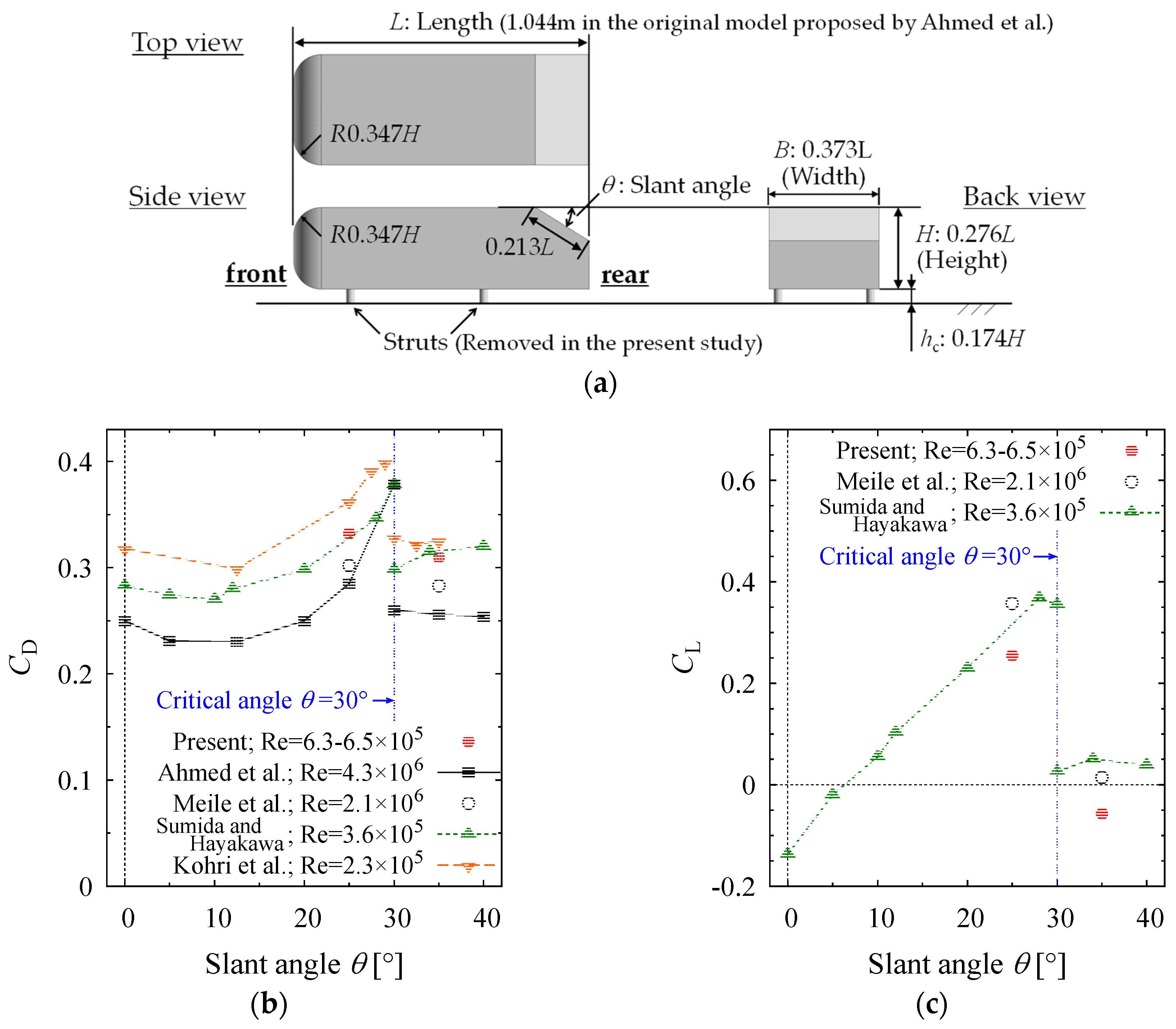
In research on automobile aerodynamics, the shapes of actual automobiles are too complicated to draw a universal conclusion. Therefore, fundamental research on automobile aerodynamics often uses a very simplified vehicle model that reproduces the essential characteristics of the flow around an automobile. The simplified model proposed by Ahmed et al. [
28], the so-called Ahmed model or Ahmed body, is one of the most famous models in the automobile aerodynamics research field. As shown in
Figure 1, this model has a smooth round head and a box-shaped body with a slant surface from the rear end of the roof to the top of the base. Only slant angle
θ is a shape parameter that affects the aerodynamic characteristics of the model. In particular, at the critical slant angle of 30°, the drag and lift change drastically with the wake structure. The differences in the wake structure and the detailed characteristics of the flow field before and after the critical slant angle have been investigated using experimental measurements [
28,
29,
30,
31] and numerical analyses [
32,
33]. Slant angles
θ = 25° and
θ = 35° have often been adopted as the subcritical and postcritical conditions. The subcritical model with
θ = 25° shows a highly three-dimensional flow (called a “three-dimensional separated (TDS) flow” [
31] or “strongly three-dimensional wake” [
32]), in which the flow separated at the leading edge of the slant surface reattaches to the surface. The post-critical flow field represented by
θ = 35° has a pseudo two-dimensional flow structure (called a “quasi-axisymmetric- separated (QAS) flow” [
31] or “quasi-two-dimensional wake” [
32]), with uniformity in the lateral direction of the model without any reattachment of the flow onto the slanted surface. These wake structures can be regarded as fast-back and square-back flows in the classification of the wake structures of automobiles [
18], respectively. Furthermore, Ahmed models with different wake structures have shown significantly different response characteristics to disturbances [
1,
4,
34]. Regarding the response to a steady crosswind condition, only the postcritical model showed aerodynamic bi-stability under a certain yaw angle condition [
4]. The responses of the wake velocity distribution and turbulence characteristics to a steady crosswind were also different between the sub- and post-critical models [
1]. The aerodynamic responses to changes in the relative wind speed [
34] also showed some different trends for the drag and lift behaviors between the sub- and post-critical models. These results implied the importance of considering the difference in the wake structure in research on the aerodynamic response of a vehicle to an on-road disturbance.
The purpose of this study was to experimentally measure the effects of a cornering motion on vehicles’ aerodynamics, especially the aerodynamic drag, and to further understand their characteristics. For this purpose, fluid-dynamic force measurements were conducted on vehicle models during cornering using a towing tank facility to experimentally clarify the cornering effects. To clarify the universal characteristics of the cornering effects, simplified vehicle models with different wake characteristics were investigated. Ahmed models with different slant angles, for which the wake structures could be categorized as those of square-back and fast-back type automobiles, were chosen as the investigated vehicle models. To validate the measurement results, the influences of the submersion depth and towing speed were investigated, and the fluid-dynamic force was compared with that in previous numerical research [
13]. Then, the cornering effects on the fluid-dynamic force were quantitatively clarified. This investigation focused on the differences in the effects between the two models, which should have depended on their different wake characteristics. Furthermore, the characteristics of the change in the fluid-dynamic force due to the cornering motion were also examined in comparison with a uniform crosswind condition. This investigation clarified the similarities and differences in the aerodynamic characteristics of a cornering vehicle compared to the steady crosswind aerodynamics that can be measured in general wind-tunnel tests.
4. Discussion
Based on the CMT results shown in
Section 3.2, the model with
θ = 35°, simulating the wake of a square-back type automobile, caused a larger drag increase due to cornering than the model with
θ = 25°, simulating the wake of a fastback-type automobile. The model with
θ = 35° showed a drag increase of 15% at
ω’ = 0.10, which represented a corner with a constant radius of 10 times the vehicle length. This drag increase corresponded to approximately 80% of the drag increase in the model with
θ = 25° at a corner with a radius of five times the vehicle length, as predicted by Keogh et al. [
13]. Because a corner with a larger radius has a higher encounter probability on the road and can be traversed at higher speeds, the drag increase at a corner with a larger radius has a greater impact on the average drag on the road. Therefore, the drag increase of the model with
θ = 35° in the present results indicated that the drag increase due to cornering motion becomes more important depending on the type of automobile and wake structure.
The changes in the side force and yaw moment due to cornering motion were also greater with θ = 35° than with θ = 25°. Here, the side force acted toward the center of the corner, and the yaw moment acted in the opposite direction to the yaw motion. Thus, the aerodynamic center of the pressure was behind the center of the vehicle. When an external centripetal force acts on a cornering vehicle at a point behind the “center of gravity” (CoG) of the vehicle, the force enhances the understeer characteristics of the vehicle and the stability of its cornering motion. This aerodynamic stabilizing effect depends on both the strength of the centripetal force and the backward distance from the CoG to the force application point. Based on the differences in the side force and yaw moment characteristics between the models with θ = 25° and θ = 35°, the centripetal side force of the model with θ = 35° was greater than that of the model with θ = 25°, while the force application point of the model with θ = 35° was further forward than that of the model with θ = 25°. Therefore, the relationship between the stabilizing effects of the models with θ = 25° and θ = 35° on the cornering motion depended on the location of the CoG.
Based on the SCW results shown in
Section 3.3, the models with
θ = 25° and
θ = 35° qualitatively reproduced the relationship of changes in drag, side force and yaw moment between the fast-back type and square-back type automobiles, respectively. The model with
θ = 35° showed greater increase of drag and side force magnitude, and smaller increase of yaw moment magnitude than the model with
θ = 25°. This tendency corresponded to the general one that the yaw angle dependency of the square-back type automobile has larger changes in drag and side force and smaller change in yaw moment than the yaw angle dependency of the fast-back type automobile [
18].
From another point of view, the effects of the crosswind components distributed in the space due to a cornering motion were investigated. The two models had different wake structures and aerodynamic characteristics depending on the slant angle at the rear end of the body. Therefore, the relative flow direction acting on the rear end of the vehicle was considered. The dependency of the fluid-dynamic force on local yaw angle
βTE is used for the discussion.
Figure 14 shows the change in the aerodynamic force measured by the CMT and SCW with respect to
βTE. For simplicity, only the fitted curves for each aerodynamic force in
Figure 12 and
Figure 13 are shown in the graphs. Here, the approximate curve of the CMT result was converted using the relationship between
βTE and
ω’ in Equation (3). The comparison based on the
βTE values also shows that the drag increase due to a cornering motion is greater than the drag increase in a uniform crosswind, while the qualitative differences in the drag increase values between the models with
θ = 25° and
θ = 35° are consistent in the CMT and SCW. Our previous study [
26] discussed the physical mechanisms generating the fluid-dynamic centripetal force due to the cornering motion and indicated that the circulation directly applied to the vehicle body by the yaw rotation generates the centripetal force due to the Magnus effect. This phenomenon would also contribute to the drag increase as its induced drag, which could be one of the reasons that the drag increase in the CMT was greater than that in the SCW.
The lift force shown in
Figure 14b only increased under a uniform crosswind condition. However, this difference was caused by a different phenomenon above the top surface of the model. Under uniform crosswind conditions, a longitudinal vortex above the top surface is formed starting at the front of the windward edge of the surface [
36]. This vertical vortex created negative pressure on the roof, which may have contributed to the increased lift. On the other hand, the cornering motion, where the wind direction is distributed, does not generate such a vortex [
13] because the local yaw angle at the center of the model is always approximately zero, and the lift did not increase.
Regarding the side force and yaw moment shown in
Figure 14c,d, consider the local fluid-dynamic response at the rear part of the model to local yaw angle
βTE.
Figure 15 shows a schematic diagram that can be referenced for the following discussion. Because
βTE becomes negative during steady-state cornering with a positive yaw rate, and the inside of the corner becomes the leeward side, it can be assumed that the local side force acting on the rear part of the model acts toward the inside of the corner. From the relationship between the changes in the fluid-dynamic forces due to cornering of the models with
θ = 25° and
θ = 35°, the model with
θ = 35° shows a greater side force toward the center of the corner than the model with
θ = 25°. The model with
θ = 35° also shows a greater yaw moment in the opposite direction of the yaw rotation than the model with
θ = 25°. Therefore, the local fluid-dynamic side force acting on the model with
θ = 35° toward the inside of the corner can be estimated to be greater than that for the model with
θ = 25°. Under a uniform crosswind condition, it can also be assumed that the side force at the rear part acts toward the leeward side and generates a yaw moment that rotates the head toward the windward direction. This increases the absolute value of Δ
CS and decreases the absolute value of Δ
CYM in the SCW results. Because the model with
θ = 35° shows a larger |Δ
CS| value and smaller |Δ
CYM| value than the model with
θ = 25°, the local fluid-dynamic side force acting on the rear part of the model with
θ = 35° can be estimated to be greater than that for the model with
θ = 25°. These estimations in CMT and SCW results were consistent with each other. Furthermore, considering that the drag increase of the model with
θ = 35° is also greater than that of the model with
θ = 25°, the model with
θ = 35° can be considered to generate a fluid-dynamic force with a greater magnitude at the rear part in response to the local yaw angle than the model with
θ = 25°.
5. Conclusions
Experimental measurements of the fluid-dynamic forces acting on cornering Ahmed models with different wake characteristics were conducted in a towing tank facility. The increase in drag due to the cornering motion, which was indicated by a previous numerical analysis by Keogh et al. [
13], was experimentally captured. Furthermore, the Ahmed model with a slant angle of
θ = 35°, which had a quasi-two-dimensional separated wake, showed a greater drag increase due to the steady-state cornering motion than the model with
θ = 25°, which had a highly three-dimensional wake structure. The drag increase of the model with
θ = 35° reached 15% when the cornering radius was 10 times the vehicle length, while the model with
θ = 25° showed a 5% drag increase under the same cornering condition. Therefore, it will be more important to consider the cornering effects on the automobile aerodynamics during the development process depending on the type of automobile and its wake characteristics.
When a consistent response is assumed for the local fluid-dynamic characteristics in the local flow direction at the rear end of the body, it is possible to qualitatively explain the relationship between the differences in the drag, side force, and yaw moment from the differences in the geometry and motion of the model. However, the amount of drag increase under the steady-state cornering condition was greater than that under the steady crosswind condition in a comparison based on the local yaw angle defined at the rear end of the model. Therefore, in the quantitative estimation of automobile aerodynamics under realistic on-road conditions, the cornering effects must be precisely reproduced and considered.


