Article

Design and Experimental Investigation of a Hybrid Rotor Permanent Magnet Modular Machine with 3D Flux Paths Accounting for Recyclability of Permanent Magnet Material

by
Adolfo Garcia Gonzalez
1,*,
Dong Wang
1,
Jean-Marc Dubus
2 and
Peter Omand Rasmussen
1
1
Institute of Energy Technology, Aalborg University, 9220 Aalborg, Denmark
2
Electrical Motor Equipment, Valeo, 94000 Creteil, France
*
Author to whom correspondence should be addressed.
Energies 2020, 13(6), 1342; https://doi.org/10.3390/en13061342
Submission received: 6 February 2020 / Revised: 2 March 2020 / Accepted: 9 March 2020 / Published: 13 March 2020
(This article belongs to the Special Issue Modular (Segmented) Electrical Machines)

Abstract

:
Rare-earth metals used for manufacturing Permanent Magnets (PMs) remain classified as critical raw materials by the European Commission. In order to secure the supply of electrical machines due to the increasing demand of Hybrid and Full Electrical Vehicles ((H)EVs), recycling has emerged as a valuable alternative. Hence, this paper presents the concept of a modular PM machine with a hybrid rotor and 3D flux paths, for application in ((H)EVs). The proposed machine topology is intended to facilitate the extraction of PM material towards a recycling process. The selection of a machine for prototyping is carried out by investigating the effect of the variation of the number of rotor teeth and stator modules on various parameters, with models developed in Finite Element (FE). Finally, the models developed of the selected combination were validated with a detailed experimental evaluation of the prototype.

1. Introduction

Electrical machines are a major component in the electrification of transportation for the reduction of CO2 emissions [1]. In order to maintain the growing demand of (H)EVs, it is required to secure the supply of Rare Earth Elements (REEs) used for manufacturing of PMs (e.g., Neodymium, Dysprosium, etc.). Nevertheless, REEs are indexed as critical raw materials by the European Commission [2], which have increased awareness regarding their recycling. The recycling of REEs has been extensively studied in various reports where the main recycling techniques have been classified, as follows [3]:
  • Re-sintering after hydrogen decrepitation,
  • Hydrometallurgical methods,
  • Pyrometallurgical methods,
  • Gas phase extraction.
The methods mentioned above have disadvantages. For instance, pyrometallurgical methods are inefficient due to the requirement of high energy input and high purity of the material processed, which is difficult to achieve with mixed scrap feeds with highly diverse compositions. On the other hand, hydrometallurgical techniques require large amounts of chemical substances and the production of large quantities of waste water. In the case of gas phase extraction, the use of hazardous chemicals is required. Finally, hydrogen decrepitation has been tested at a laboratory scale and it faces similar disadvantages regarding the composition of the scrap feed, which shall not be mixed. Therefore, the methods mentioned previously are subject of ongoing research by Work Packages 1 and 2 in the DEMETER project [4].
Regardless of the recycling method, separation and classification of PM material are important steps in order to start a recycling process. Therefore, the improvement of the recycling methods would be insufficient unless the electrical machines are designed so that the access to the PMs is facilitated once the End of Life (EoL) of the machine is reached and the motor is scrapped. Generally, PMs are either glued on, or buried inside the rotor, adding complexity to the separation from the rotor structure, and the subsequent recycling process. Therefore, it is required to start thinking about electrical machines designed for an efficient recycling of the PMs.
The investigation of electrical machines focused on feasible recycling of REEs from PMs has been reported in various studies. For instance, in [5], a transverse flux clawpole machine is proposed as a solution for facilitating recyclability. The use of Soft Magnetic Composites (SMC) is evaluated in both rotor and stator structures, based on the design developed in [6]. In [7], a case study focused on the re-use of PMs in wind turbines is proposed. The main approach is that PMs might be built in with PM segments. However, such approach might be inconvenient due to the air-gaps between PM pieces and the use of glue for holding the PM structure. Additionally, in [8], an alternative rotor structure is proposed, where the rotor is a container designed to house PM material, thus facilitating its recovery at the EoL. However, one main disadvantage of that approach might be that the recycling process shall be performed under a protective atmosphere in order to avoid oxidation, which increases the complexity of the process [9].
In [10], the use of recycled PMs in electrical machines have been studied on an Interior Permanent Magnet Machine (IPM) with bonded NdFeB PMs. In such study, PM material recycled with the hydrogen processing of magnetic scrap is used for the design and prototyping of an IPM motor. The results showed superior performance when compared with ferrite magnets. Finally, a PM assisted claw pole machine with sintered NdFeB PMs manufactured by the hydrogen decrepitation process is presented in [11]. In addition to the use of recycled PMs, the topology proposed in the study facilitates the direct re-use of the PMs which would be convenient, since additional recycling processes would not be required.
As it has been discussed above, the study of electrical machines in the context of e-mobility and recycling of PMs is of relevance. Therefore, the main goal of this paper is the definition and investigation of an alternative electrical machine topology which allows an efficient recovery of the PMs. There are, however, additional considerations on the definition of such machine. That is, the recycling of PMs of the machine is addressed in conjunction with the use of non-traditional materials (e.g., grain oriented electrical sheet, amorphous laminated material, SMC, etc.). In this regard, the use of non-traditional materials in a structure with a modular stator was investigated in [12]. Iron based amorphous laminated C-shaped cores were used in a proof of concept of a surface-mounted outer rotor machine. The main advantage of amorphous materials, such as the low level of iron losses, was validated. However, it was also observed that the PM losses were significantly large, due to the combination of a surface mounted rotor and salient structure of the modular stator. Additionally, the use of glue was required for fixing the PMs on the rotor structure, which is not convenient when addressing the recycling of PM material.
Therefore, in order to allow an efficient recycling of the PMs, the rotor structure proposed in this work is conceived in such fashion that the use of glue is not required for holding the PMs on place. Additionally, the modular stator structure proposed in [12] is expected to facilitate the extraction of the rotor. Furthermore, as it was demonstrated, it allows the use of materials that are not commonly used in rotating electrical machines.
The description of the working principle of the proposed machine is carried out in Section 2. Section 3 is devoted to the study of the increment of the torque by applying Vernier’s principle. Both the assembly process and main dimensions of the manufactured demonstrator are presented in Section 4. The experimental results are summarized in Section 5. Lastly, conclusions are drawn and future work is proposed.

2. Hybrid Rotor 3D Flux Machine

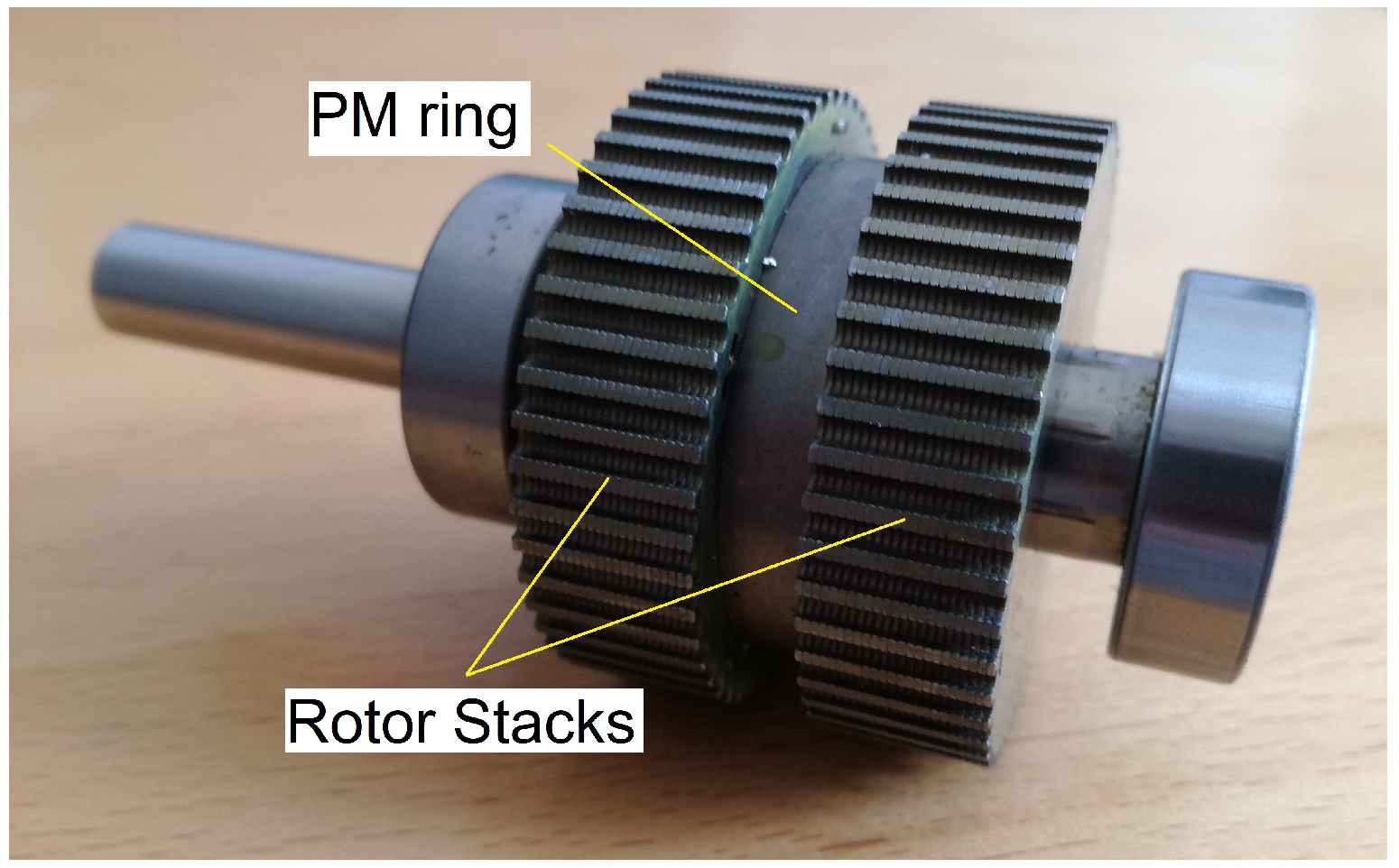
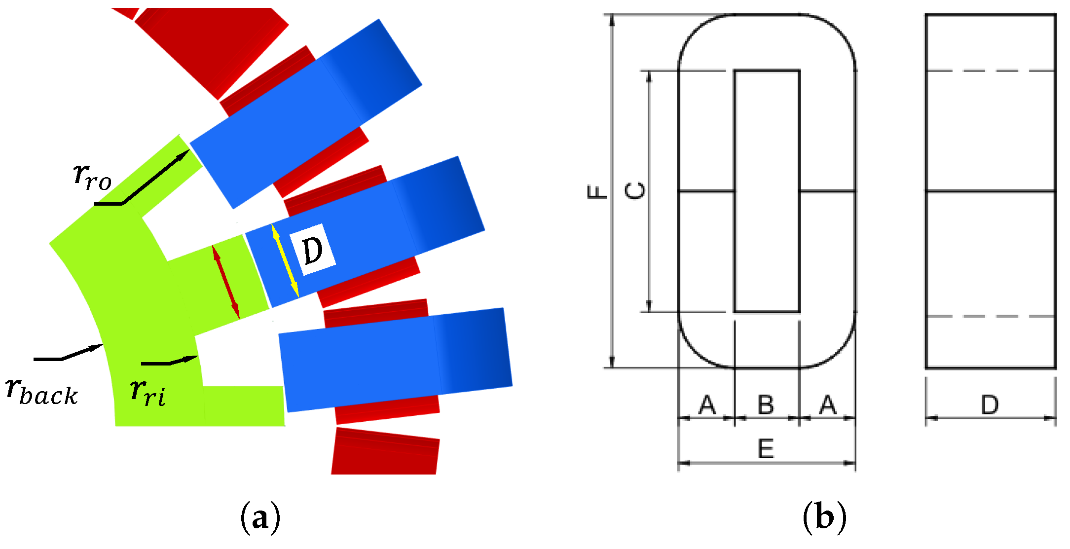
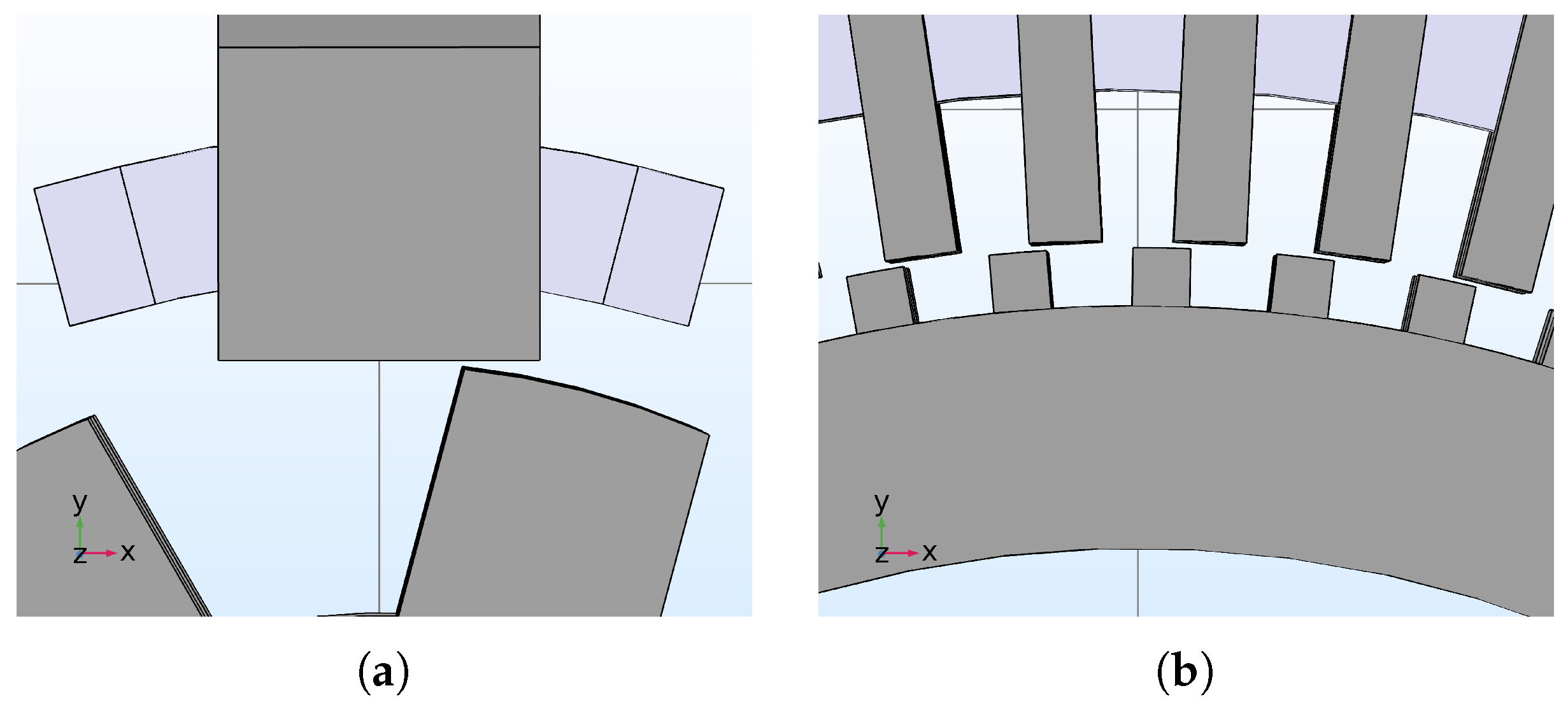
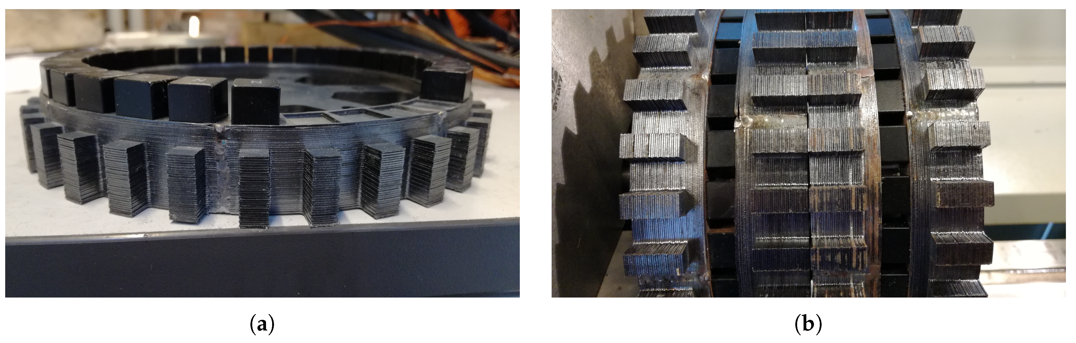
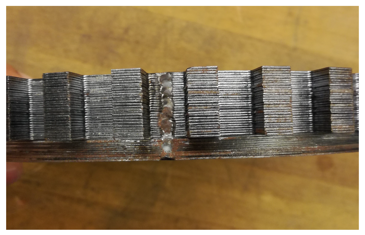
2.1. Definition of the Rotor

The term hybrid rotor used in this paper refers to the rotor geometry used in HSMs [13]. Generally, it is composed by a PM ring axially magnetized, placed in between two stacks, manufactured with electrical sheet, and with a toothed structure. Figure 1 illustrates the rotor used in an HSM.
The main advantage of having a hybrid rotor is that the PM is protected from the variations of permeance in the air-gap, due to the salient structure of the modular stator. Therefore, the losses in the PM may be reduced significantly, while, for a rotor structure with surface-mounted PMs, the PM losses were increasing with approximately the square of the frequency [12], which is not convenient in a machine with a large number of poles or running at a high speed, or both.

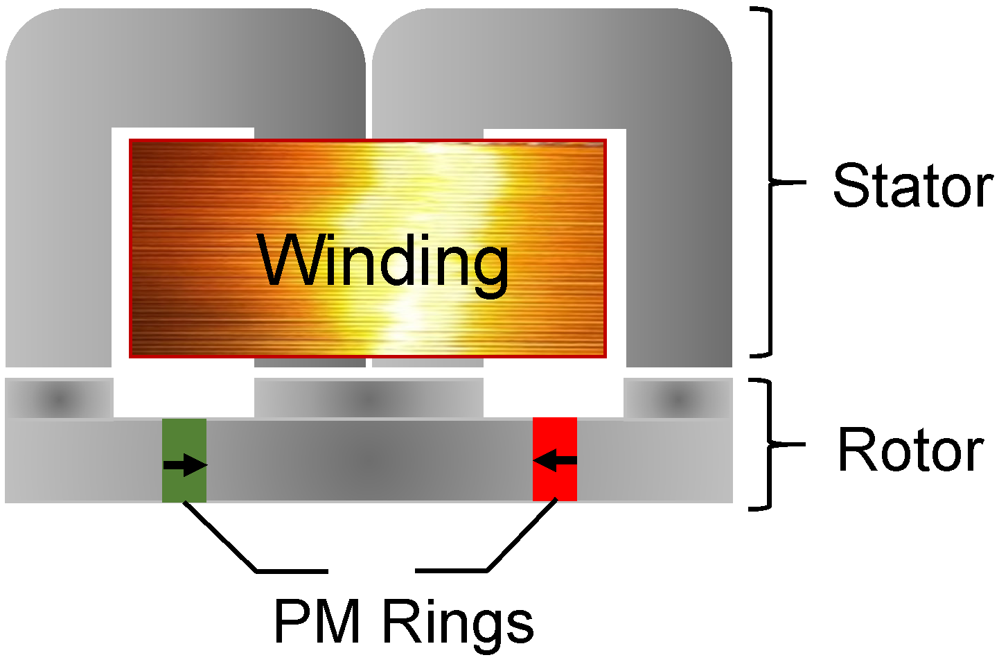
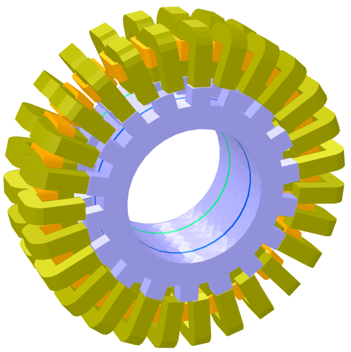
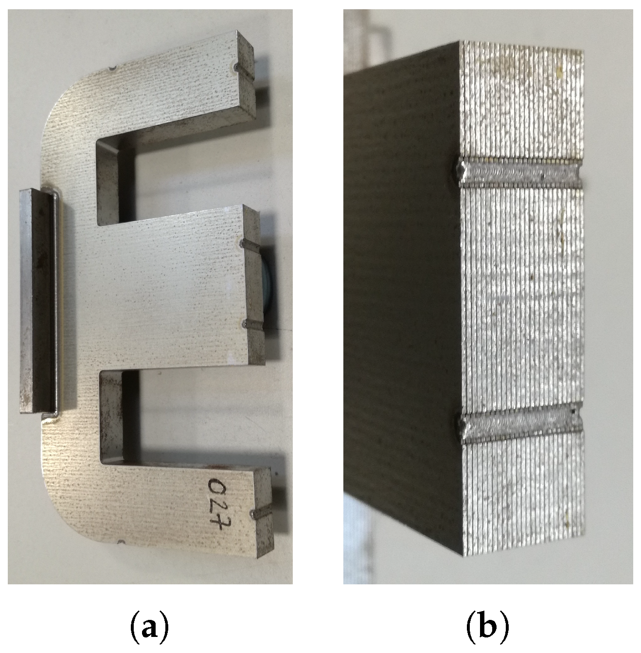
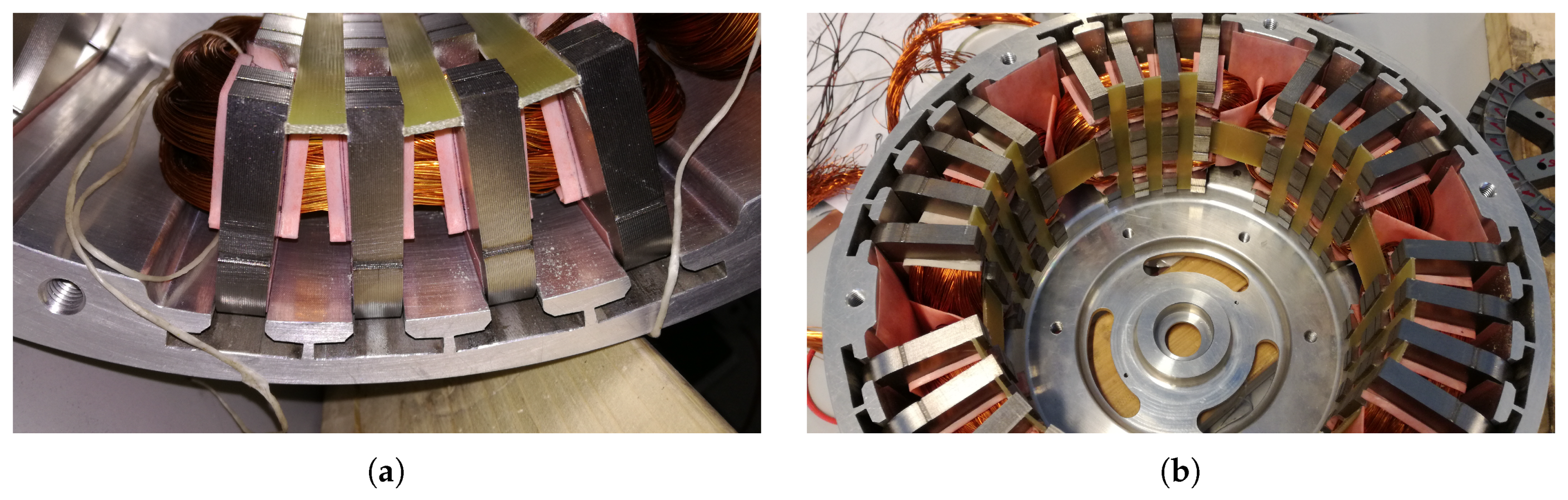
2.2. Definition of the Stator

The concept of a salient pole modular stator has been investigated in the context of switched reluctance machines. For example, in [14], an axial flux switched reluctance machine is investigated. The stator is composed by C-shaped cores in a single stack. However, the main dimensions of the prototype built for validation were not reported. An assisted switched reluctance wind power generator was investigated in [15]. Both stator and rotor of such topology share some similarities with the prototype developed in [14]. However, an excitation assistance coil is added to the rotor structure, which increases the complexity of such topology. Finally, a single stack C-shaped core is investigated in [12], where the use of laminated amorphous materials is also evaluated. As a conclusion, having a single stack of C-shaped cores might have negative effects on the performance of the machine. That is, the copper utilization is low, since approximately 3/4 of the coil are end-windings. Additionally, the overall outer diameter of the machine is increased by the end windings, which, in turn, may result in a reduction of the torque density. Therefore, the configuration of the “E-core” transverse flux machine solution proposed in [16,17] would yield an improvement on the performance by adding a second stack, in order to improve the copper utilization, and to eliminate the extra diameter required for end windings. Consequently, a double stacked structure as depicted in Figure 2 is proposed for this study. Such structure is composed by two C-shaped cores used to form an “E-core” shaped stator module, and two of the rotor stacks (Figure 1) assembled back to back.

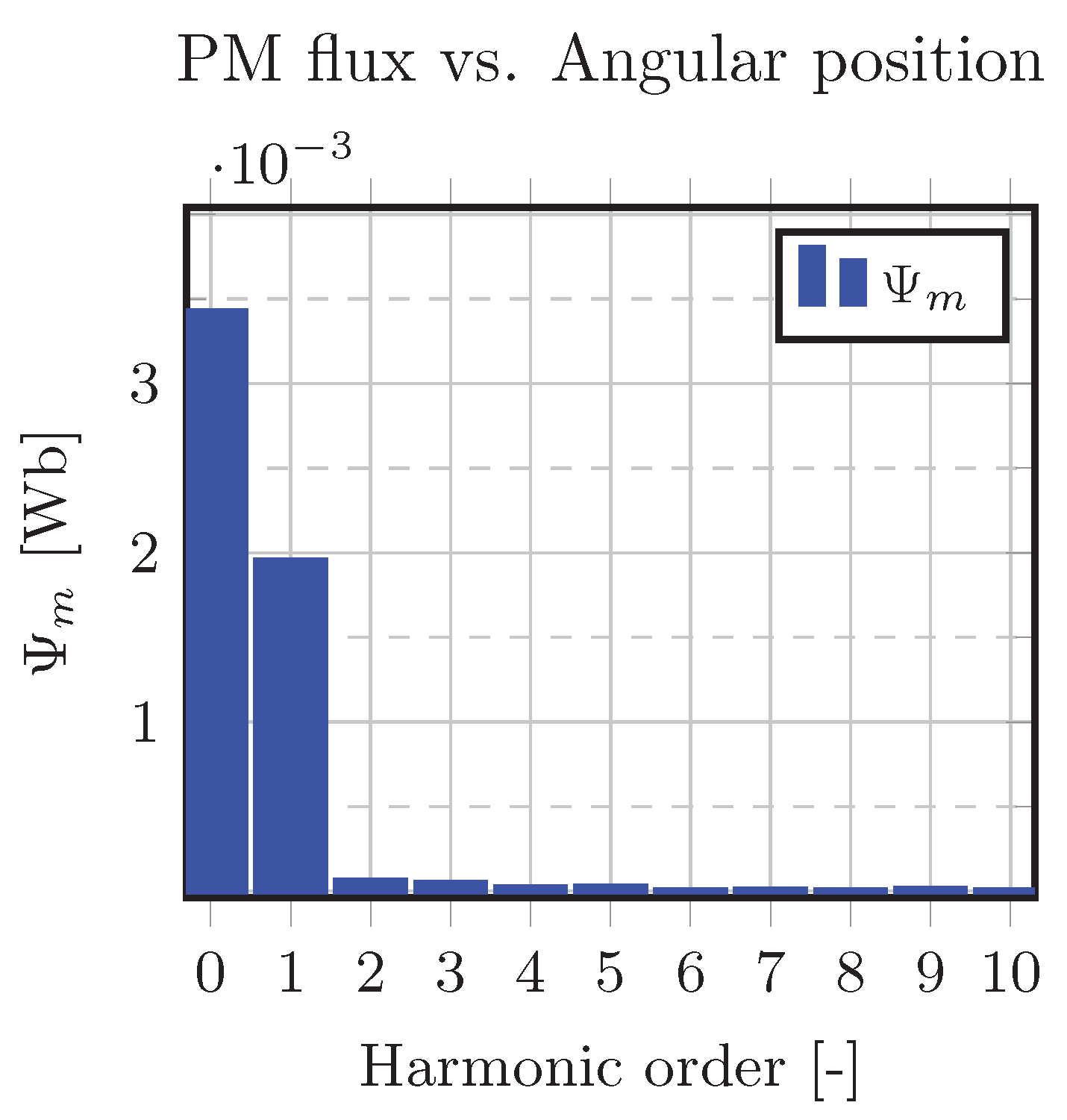
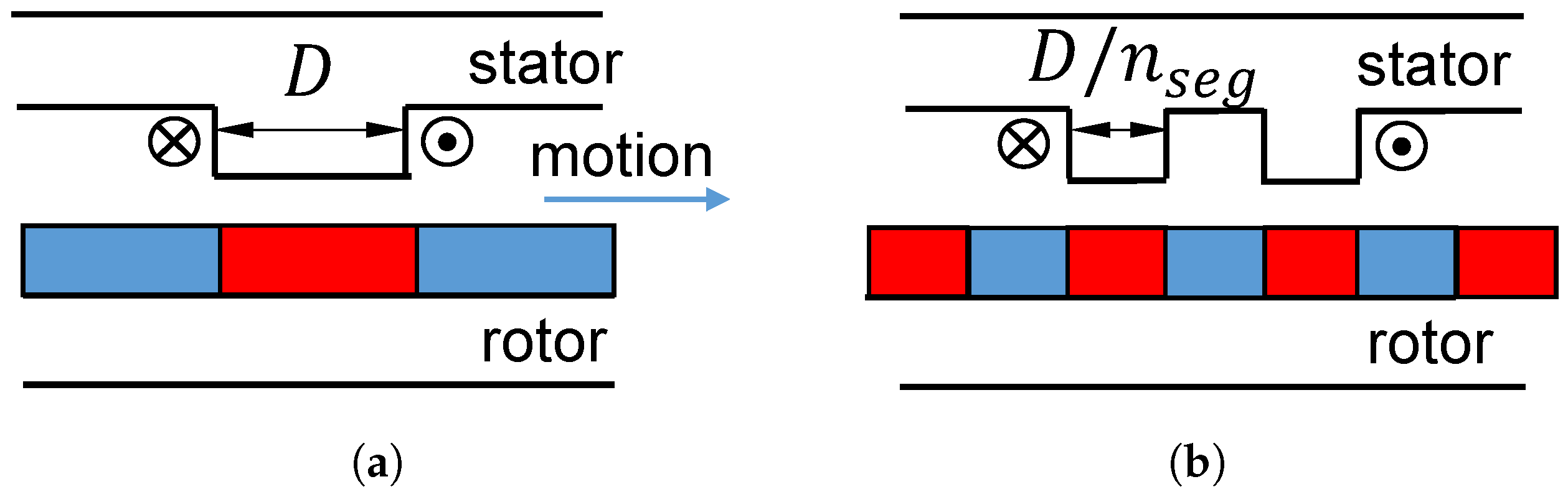
2.3. Working Principle

In order to describe the production of the PM flux linkage Ψ m , a geometry with 27 stator modules and 18 rotor teeth as in Figure 3 was built. Although the full geometry is shown in Figure 3, note that only 1/9 of the geometry was required to be solved. In addition, the coils have been removed from Figure 4 in order to facilitate the view of the flux arrows in stator modules. The coming analysis focuses on the stator module located in the middle region of Figure 4a enclosed by a black circle and labeled as number “1”. When both stator module and rotor teeth are aligned as in Figure 4a,b, a maximum value of Ψ m is reached, indicated by the arrow distribution in both the rotor and stator. If the rotor continues travelling an intermediate position is reached as in Figure 4c,d, in which the magnitude of B is lower, as it is shown by the colder color of the arrows. Finally, a minimum value of Ψ m is obtained when the position described in Figure 4e,f is reached. Note that the polarity of the magnetic flux density arrows in both the rotor and the stator does not vary.
The behavior of the PM flux linkage Ψ m with varying position is described in Figure 5. As it is observed, the flux has a sinusoidal behavior. Additionally, the PM flux is varying from a maximum to a minimum value, without crossing zero. Figure 6 shows the harmonic spectrum of the PM flux linkage waveform in Figure 5. As it has been described, the machine might be fed as any SPMSM, which facilitates its operation. In the following, the machine with hybrid rotor and modular stator investigated in this paper is referred to as the “HM3D” machine.

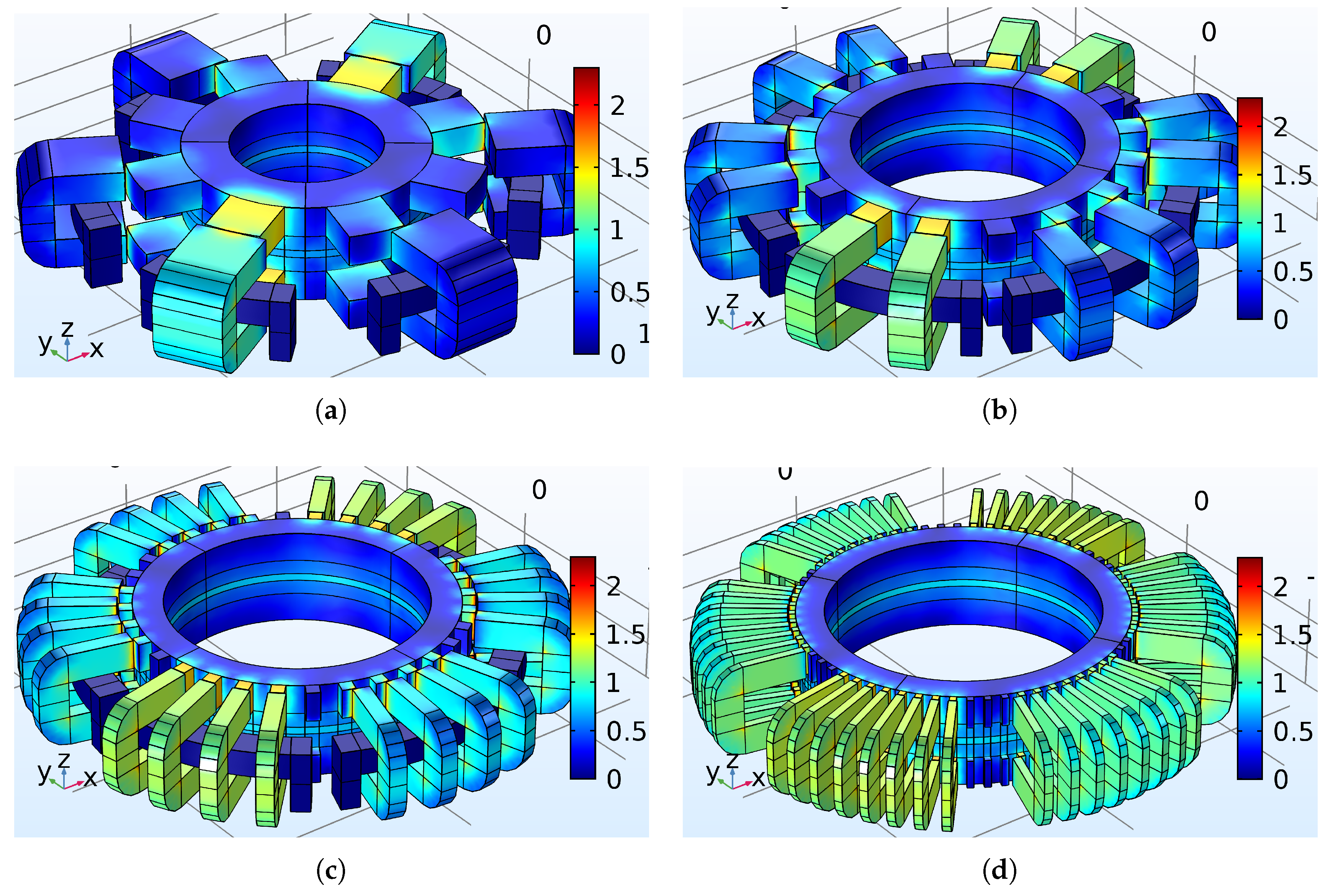
3. Study of the Vernier’s Principle

During the definition of the HM3D machine, it was found that the torque density was significantly low, with a value of approximately 2.6 N·m/L. Hence, it was decided to investigate alternatives for improving this parameter. The Vernier’s or magnetic gear principle is described in Figure 7. In order to simplify the description of the principle, a linear geometry is used in Figure 7a. In addition, Figure 7b illustrates the segmentation or sub-division of the geometry by a factor n s e g = 2. As both PM flux and MMF from the windings are kept in similar values, the force production (torque in a rotating machine) is affected directly by this factor. The force produced by the machine in Figure 7a is given by Equation (1):
F a v = Δ Ψ · N i D
where Δ Ψ is the variation of the PM flux, N i is the MMF on the windings, and D is the module width as shown in Figure 8. Once the geometry presented in Figure 7a is sub-divided by n s e g as in Figure 7b, Equation (1) may be expressed as in Equation (2):
F a v s e g = n s e g Δ Ψ · N i D
The calculation performed with Equations (1) and (2) assumes linear materials and neglects phenomena such as fringing flux and leakage. When accounting for these phenomena, there will be a value of n s e g at which a maximum increment of torque is reached, and eventually it will start decreasing. In order to evaluate the impact of the segmentation n s e g , a machine with six stator modules and eight rotor teeth was selected. Such selection is based on geometrical constraints. That is, for a fixed air-gap diameter, the increment of the parameter n s e g results in a reduction of the thickness of the module, or D in Figure 7. Therefore, such combination allows for increasing the value of n s e g , keeping D at a reasonable value. Note that the value of D with the dimensions selected for the analysis and n s e g = 8 is approximately 4.5 mm. In addition, another important requirement is the space between coils. Figure 9a shows the magnetic flux density of the original geometry. Both the stator modules and the rotor poles were sub-divided by factors n s e g = 2 (Figure 9b), 4 (Figure 9c) and 8 (Figure 9d).
In order to perform a fair comparison, the PM ring thickness l m was kept fixed at 4 mm. The dimension w m was varied accordingly in order to keep similar volume of the PM material in the four cases. The main PM dimensions are illustrated in Figure 10.Additionally, the dimensions of the modules selected for the analysis are according to Figure 8b: A = 16 mm, B = 20 mm, C = 70 mm. The dimension D varies according to the number of sub-divisions. The results of torque increment along with additional parameters, and main dimensions are summarized in Table 1.
As it was described previously, the increment of the factor n s e g yields a reduction of the thickness of the stator modules, for the same air-gap diameter. Given that the surface of the stator modules facing the air-gap is flat, and the circumference of the rotor is kept constant, the result is a reduction of the equivalent air-gap length. In order to illustrate such hypothesis, a detailed view of the air-gap is shown in Figure 11. The air-gap of the HM3D machine with n s e g = 1 is shown in Figure 11a, whereas the air-gap of the HM3D machine with n s e g = 8 is shown in Figure 11b. In consequence, the PM flux linked by the stator modules in un-aligned position increases with the number of segments, as it is observed with the transition to warmer colors in the stator modules that are not aligned from Figure 9a to Figure 9d.
Preliminary conclusions may be drawn from the results obtained so far:
  • As anticipated, the increment of torque is not directly proportional to the increment of sub-divisions.
  • For the same amount of current, the power factor decreases dramatically.
  • The fundamental frequency is increased with number of sub-divisions. Hence, the iron losses increases substantially.
The use of amorphous laminated material was expected to improve the level of iron losses of the HM3D machine. Therefore, having a machine with a high fundamental frequency was not a concern. In addition, a higher priority was put on torque production rather than on power factor. Hence, the structure with n s e g = 4 was selected for the manufacturing of a prototype. Further parameters are analyzed for such configuration in Section 5.

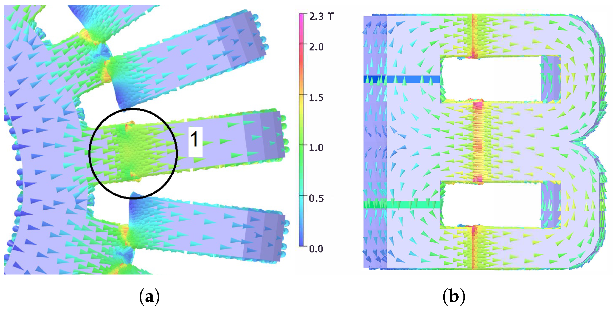
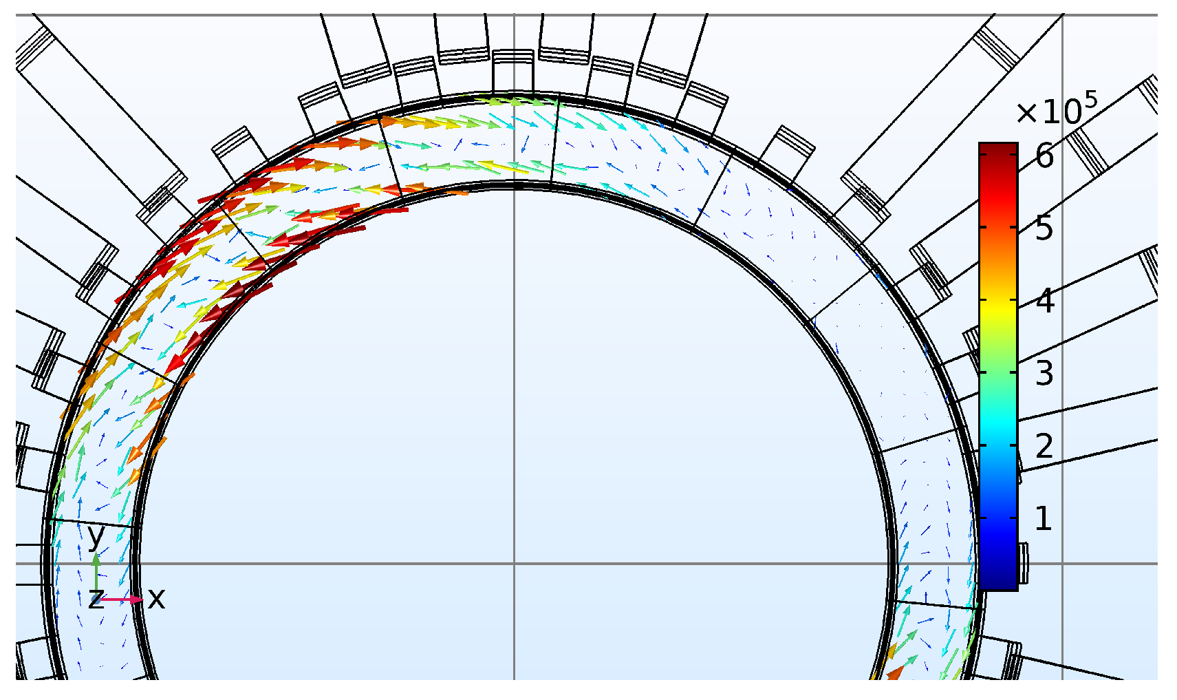
Estimation of the PM Losses in the HM3D Machine

The reduction of the PM losses due to slotting effect was the main motivation for investigating a hybrid rotor machine. Hence, the PM losses were estimated on the selected model with n s e g = 4 (Figure 9c). Various considerations were adopted in the calculation of the PM losses:
  • The rated speed of the machine in “performance” mode was specified as 2300 rpm.
  • The conductivity of the PM ring was set as 1.25 MS/m.
  • Only PM losses due to slotting effect were calculated. That is, the contribution of the PM losses by the time and space harmonics is not evaluated.
Transient simulations were run and the current density in the PM ring at 2300 rpm, and t = 0.68 ms is illustrated in Figure 12. In addition, the PM losses were estimated during an electrical cycle. At 2300 rpm, the electrical frequency of the machine with n s e g = 4 is 1226 Hz. The behavior of these with time are illustrated in Figure 13.
As it is observed, the PM losses oscillates with a frequency three times larger than the fundamental frequency, as a result of the PM ring seeing six variations during a complete electrical period. In addition, the maximum values of eddy currents are concentrated in the regions between coils, where the largest air regions in the stator are located (Figure 12). The PM losses in the PM ring reached a value of approximately 6 W, which might be highlighted as an advantage of adopting a hybrid rotor structure similar to the one described in Figure 1.

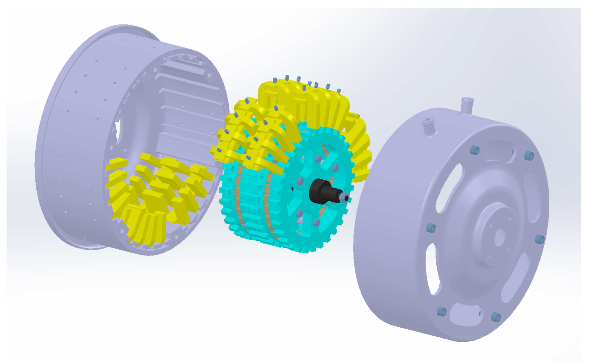
4. Assembly of the Demonstrator

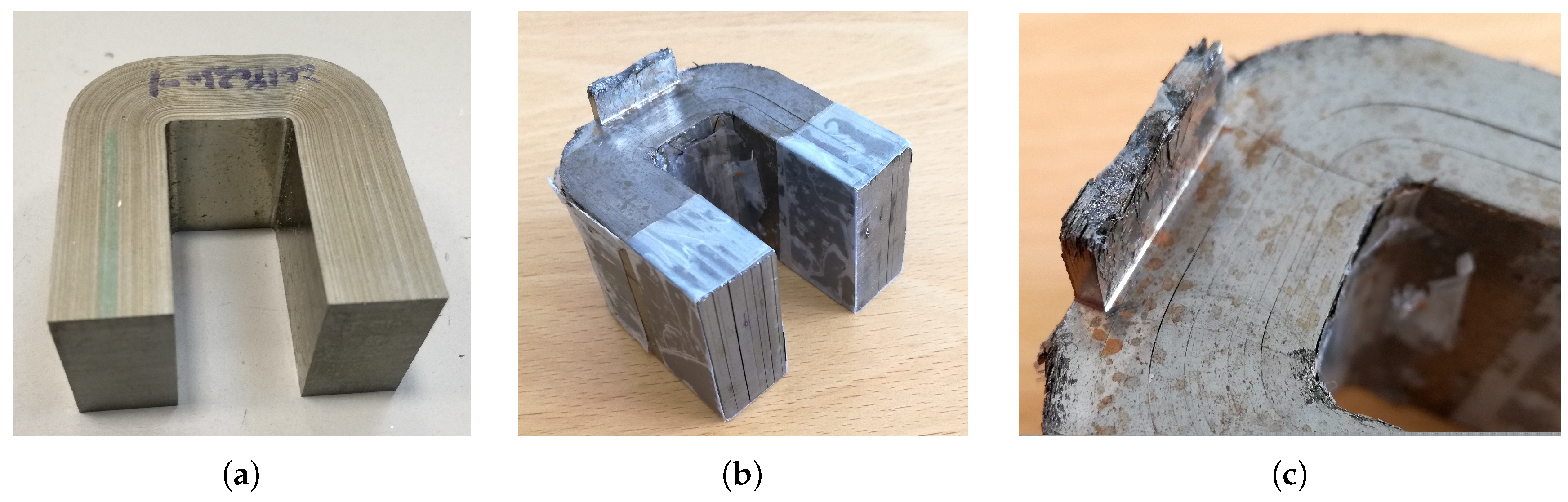
4.1. Stator Assembly

The main components of the HM3D machine, rotor, stator bracket, modules, and end-shield are described with the CAD geometry in Figure 14. During the definition of the mechanical design, major changes in the stator structure were required. Initially, the HM3D machine was conceived for using amorphous laminated material. However, there were difficulties with the lead time of the suppliers due to the complexity of the fixing mechanism of the modules to the stator bracket. In an attempt to modify the modules to obtain the dimensions and shape required, the cut of one of the C-shaped amorphous modules was tested. Figure 15a illustrates the module as supplied by the manufacturer. After the milling process, the module tested suffered significant damage, as it is depicted in Figure 15b. The lamination stack separated in various regions, and the external laminations were damaged as it is shown in Figure 15c.
Consequently, stator modules manufactured with electrical sheet M300-35A were used instead. The supplied modules are illustrated in Figure 16, where a general view is presented in Figure 16a. Figure 16b shows a detailed view of the stacking of the laminations in the module. Nevertheless, the modules were expected to be stacked in the opposite direction, that is, as in the amorphous C-shaped cores in Figure 15. In addition, the use of welds, as illustrated in Figure 16b, have a negative impact in the performance of the machine, since it is creating a path for eddy currents to flow. Although the models developed did not account for such issues, the effect of the welds on the production of back-EMF is investigated in Section 5.
Figure 17 describes both the assembly of the coils with Figure 17a, and the complete stator assembly with Figure 17b. Despite the modular approach adopted for the stator, it was possible to use standard materials, such as fibre-glass wedges for holding the coils in place, as in a standard machine. On the other hand, the slot fill factor k f i l l achieved was approximately 0.25.

4.2. Rotor Assembly

Similarly to the stator assembly, significant changes were performed to the rotor structure. The PM rings used during the definition of the model, were replaced by PM blocks. Such PM blocks correspond to sintered NdFeB material protected by a sprayed layer of epoxy. The grade of the PMs corresponds to F40SH, with a remanence B r = 1.31 T, according to the data-sheet [18] of the manufacturer. The assembly of the rotor structure is depicted in Figure 18. The electrical sheet used for the rotor were of M600-50A quality. First, the PM blocks were placed around one of the stacks, as in Figure 18a. The assembly of the rotor was completed with a lathe, due to the resulting large attractive forces when assembling two rotor stacks together. Figure 18b shows the assembly of the complete rotor. The implementation of PM blocks instead of a single PM ring might have a negative impact when evaluating the recyclability from the assembly and disassembly perspectives [19]. In theory, having least PM pieces, would be convenient since the time for assembly of the rotor would be reduced. However, the use of PM blocks might be convenient since having simple PM shapes reduces the complexity in the selection and manufacturing of the PM blocks. Regardless of using either a complete PM ring, or PM blocks, the rotor configuration allows the assembly of the PMs without the requirement of glue, which may be highlighted as one of the main advantages of the HM3D machine.
Quality issues were spotted in the components supplied by the manufacturer. For example, the stacking, and cutting of the rotor might be improved, as it is shown in Figure 19. Furthermore, the irregular stacking of the stator might lead to an irregular air-gap length. In addition, the use of welds on the surface of the rotor shall be avoided.

5. Experimental Results

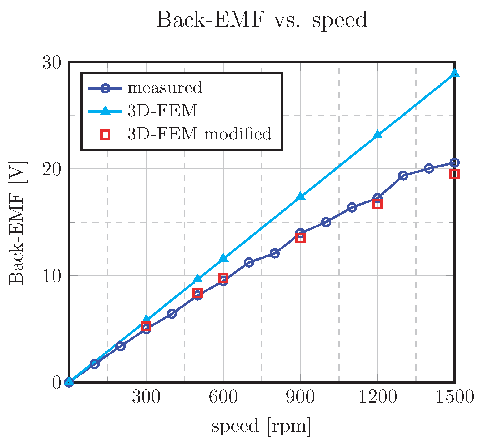
5.1. Measurement of Back-EMF

The set-up for the measurement of no-load parameters is shown in Figure 20. As a start, the prototype was driven as a generator coupled to a servomotor through a torque transducer. The waveforms of the back-EMF phase to neutral at a speed of 500 rpm are shown in Figure 21.
It might be noticed that the peak values in each phase do not have identical magnitude, with a maximum deviation between phases of approximately 4%. Such deviations might be a result of eccentricities as a result of having a stator with a modular structure. The variation of the back-EMF with speed was also investigated. Ideally, the back-EMF should follow a linear trend, as it is depicted by the calculated 3D-FEM plot in cyan color in Figure 22. However, the measured values in dark blue start reducing as the speed increases, showing a deviation of approximately 16% at 300 rpm and a deviation of 40% at 1500 rpm. As it is observed, such deviation is speed dependent, which is an indication that the reduction is due to frequency dependent phenomena and not due to the nonlinearity of the materials (i.e., saturation)—specifically eddy currents. Hence, an initial hypothesis is that such deviations are generated by eddy currents due to the welds on the surface of the stator modules. In order to verify such hypothesis, the FEM model was modified so it accounted for the welds. Hence, conductive volumes surrounding the stator modules in one phase were built as it is shown in Figure 23, with the conductivity of iron (i.e., σ F e = 1.12 MS/m). The calculated values with the stator modified are included in red in Figure 22. As it is observed, the calculated values with the modified model follows a similar trend. In addition, both deviations at 300 and 1500 rpm were reduced to approximately 5% in both cases.
The short circuit coil produced by the welds on the stator modules facilitates the circulation of currents once the time varying flux starts flowing in the stator. Such currents generate a flux which is opposing the main flux circulating in the stator modules. Hence, as the speed increases, such currents increase and yield a larger deviation as it was described in Figure 22.

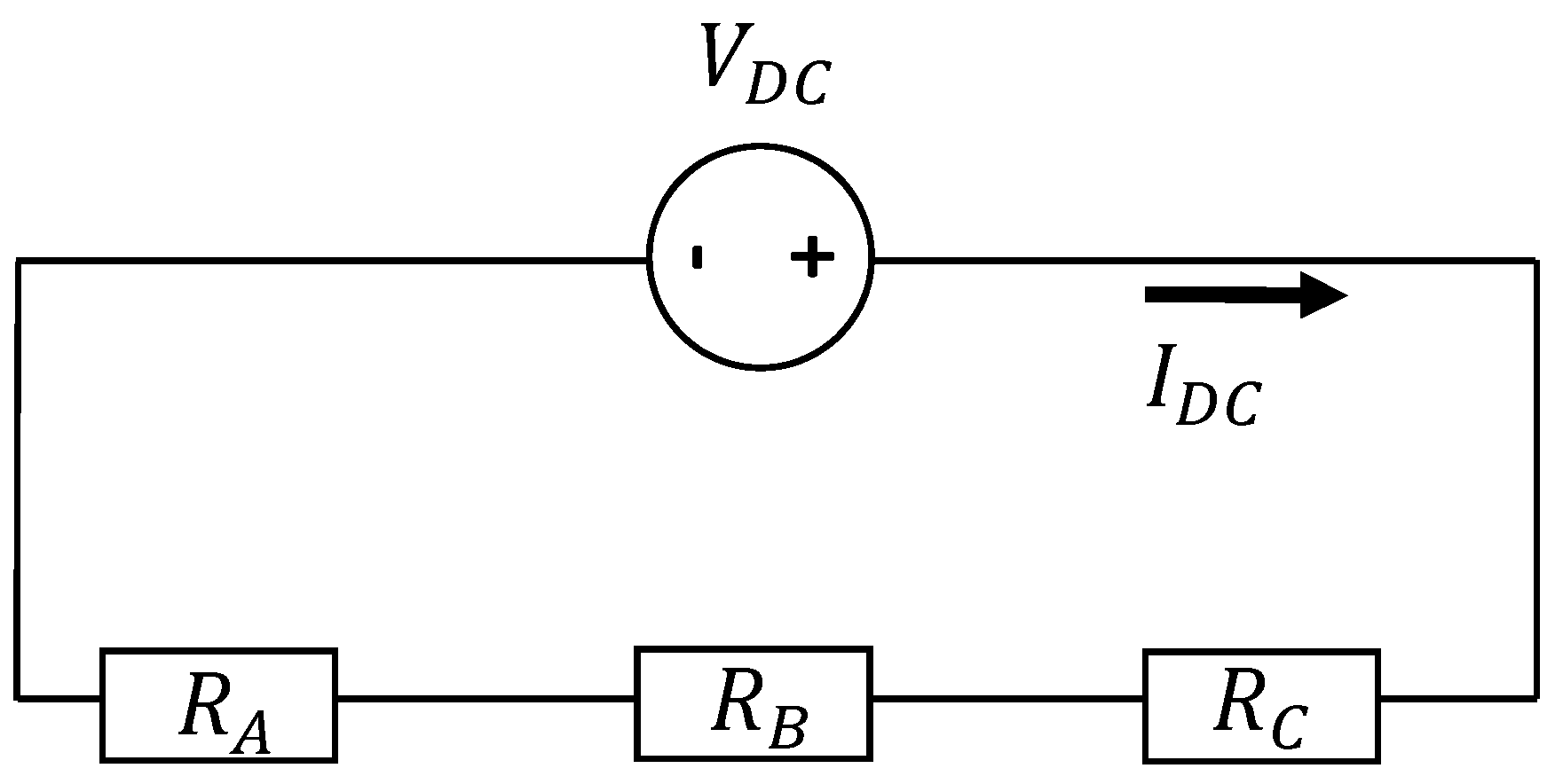
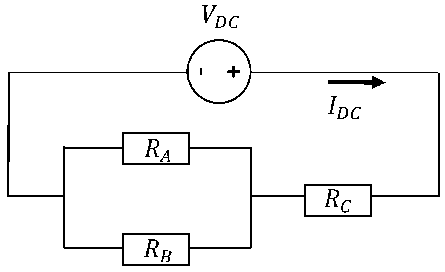
5.2. Measurement of Inductance

The inductance per phase was measured with a Precision Magnetics Analyser®. At various frequencies, the inductance profile is illustrated in Figure 24. The results of both the DC resistance and inductances are summarized in Table 2.
Regarding the calculated values with FEM, the deviation in the calculation of L d and L q was of approximately 11% and 6%, respectively. Similar deviations would be expected, but, as it was pointed out in Section 4, the quality issues of the rotor might be reflected in the measured values. In addition, the saliency of the HM3D machine according to the measurements is of approximately 5%.

5.3. Measurement of Temperature Distribution

The thermal behavior of the HM3D machine was of concern during the definition of the mechanical design due to both the modular structure of the stator and the fixing mechanism of the coils to the modules. For testing, the windings were connected in series, and a DC current was applied to the available terminals, as it is described by the circuit in Figure 25. The maximum current density for the prototype with air natural convection was defined as 6.5 A/mm2. Hence, a DC current of I D C = 100 A was applied until the temperature was stabilized.
Three T-type thermocouples were placed on the prototype. Figure 26 describes their locations on the windings, stator modules, and stator bracket. The temperature evolution in each component with time is shown in Figure 27. After 14,700 s, the highest temperature corresponded to the windings with a temperature rise of 90.5 K. The temperature rise in both the stator modules and stator bracket reached 44.5 K. Hence, the measured temperature gradient between the windings and the stator components was approximately 46 K. The ambient temperature during the test had a constant value of 25.5 C.
For verifying the thermal capability of the machine, the equivalent convection coefficient h e q is introduced. Such coefficient is estimated with Equation (3):
h e q = 1 R t h A h e
where A h e is the area of the heat exchange surface, R t h = Δ T / p c u corresponds to the equivalent thermal resistance, with Δ T and p c u as the measured temperature gradient and copper losses. With the geometry of the HM3D machine, the estimated h e q is of approximately 190 [W/m2/C], which would correspond to a machine with air forced convection [20]. Finally, although the prototype was equipped with water cooling, such option was not tested.

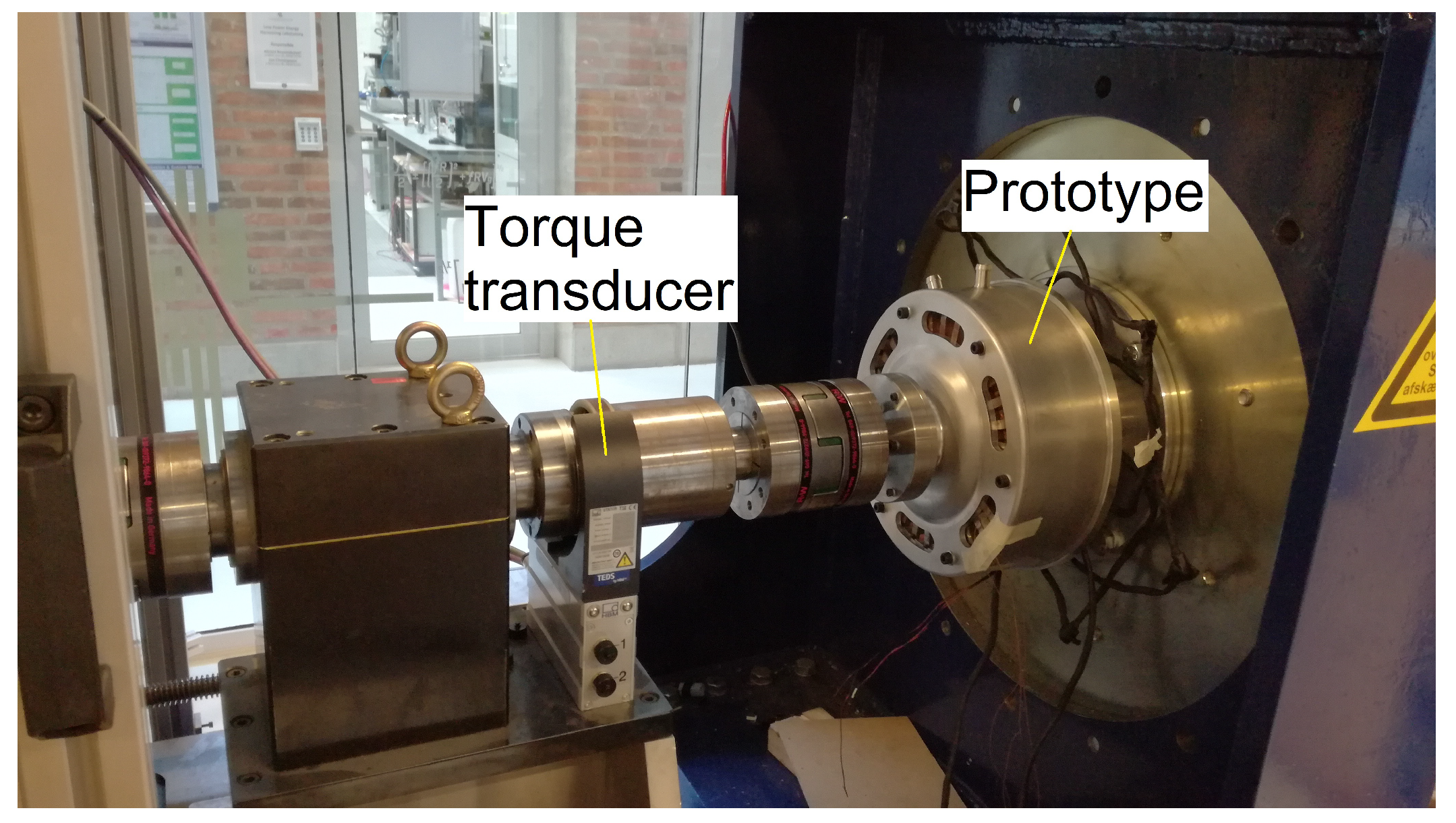
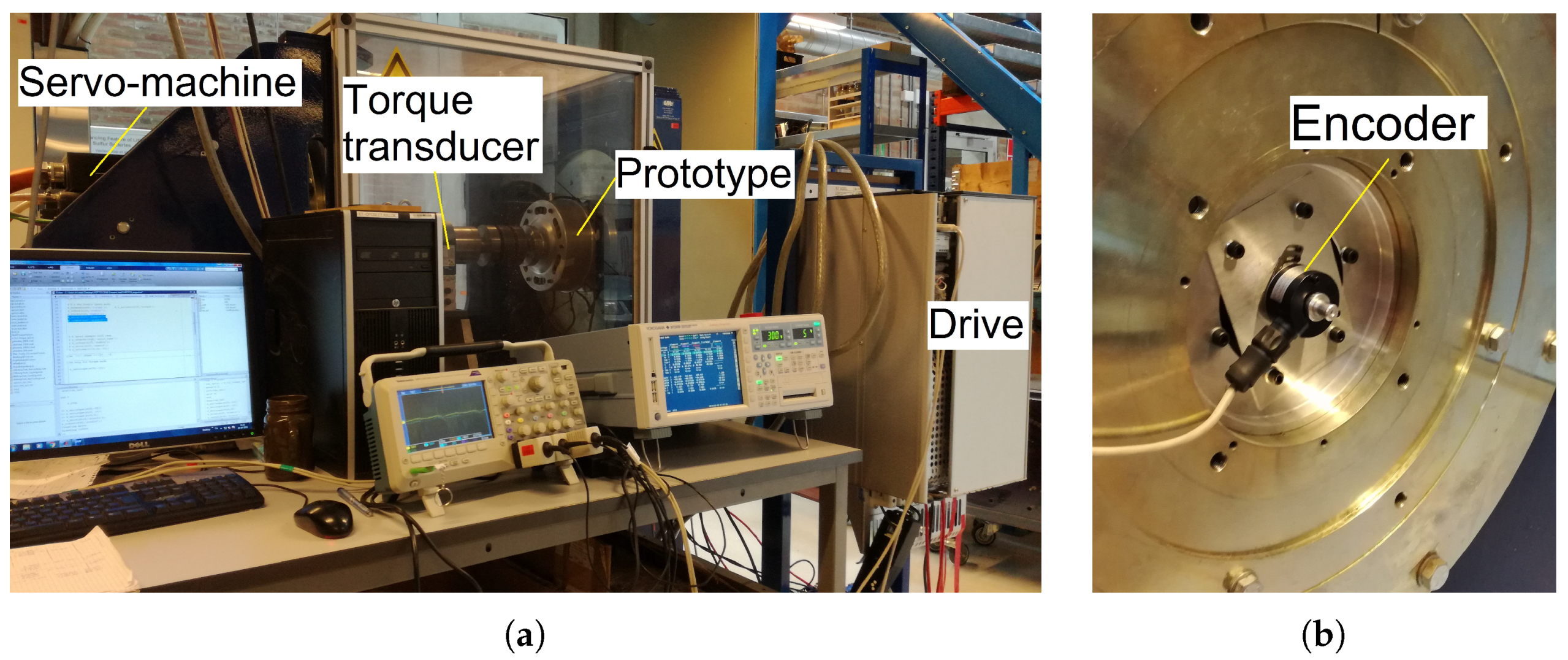
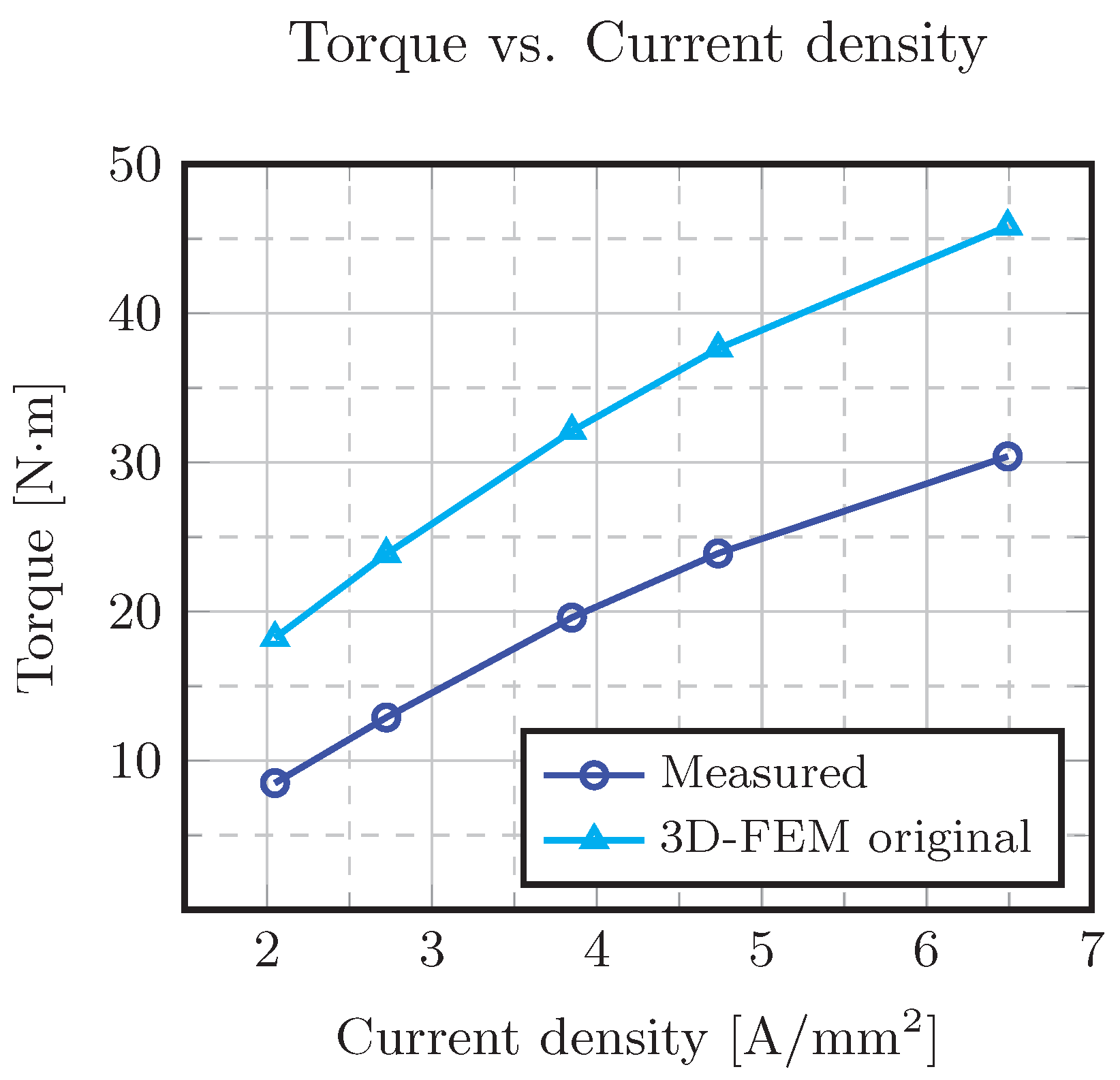
5.4. Measurement of Torque

The measurement of torque was performed with the set-up described by Figure 28a. The prototype was fed with a VLT® AutomationDrive FC302 from Danfoss. Readings of torque and speed were registered. The current measured during the test was applied to the model in FEM.
As it is observed in Figure 29, the deviation between the calculations and the measurements starts increasing as the speed increases. At a current density of 2 A/mm2, the deviation is of 9.7 N·m. At a current density of approximately 6.5 A/mm2, the deviation increases to 15.4 N·m. Here, it is worth noting that neither the effect of the welds in the stator modules nor the harmonics due to the PWM modulation were evaluated in the FEM calculations. Despite the large deviations obtained in the measurement of torque, the efficiency was measured at various points of torque and speed, and the values are illustrated in Figure 30.
Due to both the reduction of torque production and the large value of rotational losses, the efficiency of the HM3D machine is rather low. In order to eliminate the effect of both PWM modulation and welds on the stator modules, the machine was connected to a DC power source as described in Figure 31. The shaft was rotated with a metallic lever in order to obtain the maximum value of torque, when rotating the shaft a complete electrical period. The measured and calculated values of torque are shown in Figure 32.
The deviation between both measured and calculated values have a constant value of approximately 7 N·m. Such deviation might be originated by various factors: the air-gap length that might not be continuous around the stator circumference. In addition, the laminations in both stator and rotor might be subjected to degradation during the cutting and stacking processes, which is not accounted for in the FEM models developed.

5.5. Rotational Losses

Three approaches were used in the measurement of the rotational losses:
  • A spin-out or decay test. Such test consisted in rotating the shaft with an external device, specifically, a drill. The decaying waveform of the back-EMF is registered [21]. The rotational losses are obtained with the inertia of the machine J.
  • Running the prototype as a generator, with a servomotor and registering values of torque and speed. The rotational losses were the product of the mechanical speed and the torque measured at no-load.
  • Running the machine as a motor, fed with a converter and registering both the output and input power in order to obtain the rotational losses.
The rotational losses measured with the three methods described previously are illustrated in Figure 33. In addition, the iron losses calculated with FEM are included. The lowest values correspond to the simulated losses noting that the mechanical losses are not included in their calculation. In addition, the calculations of losses with both electrical sheet and amorphous materials, do not account for the short circuit turn, investigated in the section of back-EMF measurements.
On the other hand, the measured rotational losses as generator (in blue color) are larger than the calculated values by a factor of approximately 2. Furthermore, the rotational losses measured with the HM3D machine running as motor (in black color) are larger by a factor of approximately 4 than the iron losses calculated with FEM. Such trend may be explained by the presence of the short circuit turn, the MMF of the no-load current which is altering the waveform of the magnetic flux density in the different regions of the magnetic system, and the harmonic content due to the modulation of the PWM of the converter used in the test.
The variation of the rotational losses with increasing current density was evaluated with measured values during torque measurements. The rotational losses p 0 were determined with Equation (4):
p 0 = P i n p c u P o u t
where P i n is the power measured at the machine terminals with the power analyser, p c u are the copper losses, and P o u t is the power measured in the shaft. The results of the rotational losses are presented in Figure 34.
As it is observed, there is a significant impact of the MMF and the PWM modulation on the rotational losses. The increment of these reached a maximum of 10 times the losses at generator mode where the impact of the current and the PWM are not present. In summary, the high level of iron losses reached are reflected in the low efficiency of the HM3D machine presented in Figure 30.

5.6. Main Dimensions of the HM3D Machine

Finally, the main dimensions of the HM3D machine are summarized in Table 3.

6. Conclusions and Future Work

An alternative topology with a hybrid rotor in conjunction with a modular stator was proposed and studied in this paper. Regarding recyclability, various advantages were identified on the HM3D machine [19]:
  • The use of glue for assembling the PMs to the rotor is not required, facilitating the extraction of the PMs for a subsequent recycling process.
  • The modular approach of the stator facilitates the access to the rotor, and, consequently, the PM material in the rotor, allowing the use of materials that are not usually found in rotating electrical machines.
Finally, a significant reduction of PM losses due to slotting effect is reached with the hybrid rotor structure.
However, the manipulation and processing of the amorphous laminated cores proved to be challenging. Additionally, although there are manufacturers able to supply the modules with required dimensions, the method for fixing the modules to the stator bracket proved to be the main issue. Therefore, further work might be required in order to improve the assembly of the modules to the stator. On the other hand, a stator with a modular structure proved to have thermal issues due to the large temperature rise reached between windings and stator frame. Improving the slot fill factor would allow a reduction of the losses, and, consequently, the reduction of the temperature rise. Additionally, alternatives to improve the heat transfer between the coils, modules, and stator bracket (e.g., the use of casting resins, etc.) are proposed as future work.
Due to imperfections in the manufacturing of both stator and rotor components, the performance of the machine was rather poor in terms of both torque production and efficiency. Both the use of amorphous laminated material and improvements on the manufacturing of the rotor would allow the reduction of the iron losses, and, consequently, the increment of efficiency. Nevertheless, the HM3D machine proved to have both poor torque density and power factor, which raises questions about the convenience of such topology.
Lastly, the study of the PM losses shall be extended to the estimation of these accounting for both time and space harmonics. Furthermore, it would be required to evaluate the behavior of the PM losses on the PM blocks, given the change of the equivalent resistance, when changing from a complete PM ring, to individual blocks.

Author Contributions

Conceptualization, A.G.G. and P.O.R.; investigation, A.G.G; resources, J.-M.D.; supervision, P.O.R., D.W., and J.-M.D.; writing—original draft, A.G.G.; funding acquisition, P.O.R. All authors have read and agreed to the published version of the manuscript.

Funding

The research leading to the results presented in this article has been funded by the European Community’s Horizon 2020 Programme ([H2010/2014-2019]) under Grant Agreement No. 674973 (MSCA-ETN DEMETER). This publication reflects only the authors view, exempting the Community from any liability—project website http://etn-demeter.eu/.

Conflicts of Interest

The authors declare no conflict of interest.

References

  1. EAFO.eu. The Transition to a Zero Emission Vehicles Fleet for Cars in the EU by 2050. 2017. Available online: http://www.eafo.eu/sites/default/files/The%20transition%20to%20a%20ZEV%20fleet%20for%20cars%20in%20the%20EU%20by%202050%20EAFO%20study%20November%202017.pdf (accessed on 28 March 2019).
  2. European Commission. Critical Raw Materials | Internal Market, Industry, Entrepreneurship and SMEs. 2018. Available online: http://ec.europa.eu/growth/sectors/raw-materials/specific-interest/critical_en (accessed on 1 April 2019).
  3. Binnemans, K.; Jones, P.T.; Blanpain, B.; Gerven, T.V.; Yang, Y.; Walton, A.; Buchert, M. Recycling of rare earths: A critical review. J. Clean. Prod. 2013, 51, 1–22. [Google Scholar] [CrossRef]
  4. DEMETER. European Training Network for the Design and Recycling of Rare-Earth Permanent Magnet. Available online: https://etn-demeter.eu/project (accessed on 4 December 2018).
  5. Alatalo, M.; Lundmark, S.T.; Grunditz, E.A. Electric machine design for traction applications considering recycling aspects-review and new solution. In Proceedings of the IECON 2011—37th Annual Conference of the IEEE Industrial Electronics Society, Melbourne, Australia, 7–10 November 2011; pp. 1836–1841. [Google Scholar] [CrossRef]
  6. Lundmark, S.K.T. Application of 3D Computation of Magnetic Fields to the Design of Claw Pole Motors. Ph.D. Thesis, Chalmers University of Technology, Gothenburg, Sweden, 2005. [Google Scholar]
  7. Högberg, S.; Pedersen, T.S.; Bendixen, F.B.; Mijatovic, N.; Jensen, B.B.; Holbøll, J. Direct reuse of rare earth permanent magnets—Wind turbine generator case study. In Proceedings of the 2016 XXII International Conference on Electrical Machines (ICEM), Lausanne, Switzerland, 4–7 September 2016; pp. 1625–1629. [Google Scholar] [CrossRef]
  8. Kjeldsteen, P.; Sørensen, A.I.; Bendixen, F.B. A Permanent Magnet Rotor for a Machine, a Method for Manufacturing a Permanent Magnet Rotor and a Manufacturing System. WO/2010/066251. 17 June 2010. Available online: https://patentscope.wipo.int/search/en/detail.jsf?docId=WO2010066251&tab=PCTBIBLIO (accessed on 14 October 2018).
  9. Höegberg, S.; Bendixen, F.B.; Mijatovic, N.; Bech Jensen, B.; Holbøll, J. Influence of demagnetization-temperature on magnetic performance of recycled Nd-Fe-B magnets. In Proceedings of the 2015 IEEE International Electric Machines Drives Conference (IEMDC), Coeur d’Alene, ID, USA, 10–13 May 2015; pp. 1242–1246. [Google Scholar] [CrossRef]
  10. Kimiabeigi, M.; Sheridan, R.S.; Widmer, J.D.; Walton, A.; Farr, M.; Scholes, B.; Harris, I.R. Production and Application of HPMS Recycled Bonded Permanent Magnets for a Traction Motor Application. IEEE Trans. Ind. Electron. 2018, 65, 3795–3804. [Google Scholar] [CrossRef] [Green Version]
  11. Upadhayay, P.; Awais, M.; Lebouc, A.; Garbuio, L.; Degri, M.; Walton, A.; Mipo, J.; Dubus, J. Applicability of Direct Reuse and Recycled Rare Earth Magnets in Electro-mobility. In Proceedings of the 2018 7th International Conference on Renewable Energy Research and Applications (ICRERA), Paris, France, 14–17 October 2018; pp. 846–852. [Google Scholar] [CrossRef]
  12. Gonzalez, A.G.; Wang, D.; Rasmussen, P.O. Investigation of a Surface Mounted PM Machine Concept with 3D-Flux Paths, Modular Stator and Amorphous Material. In Proceedings of the 2019 IEEE International Electric Machines Drives Conference (IEMDC), San Diego, CA, USA, 12–15 May 2019; pp. 739–744. [Google Scholar] [CrossRef]
  13. Kenjo, T.; Sugawara, A. Stepping Motors and Their Microprocessor Controls; Monographs in Electrical and E; Clarendon Press: Oxford, UK, 1994. [Google Scholar]
  14. Labak, A.; Kar, N.C. Designing and Prototyping a Novel Five-Phase Pancake-Shaped Axial-Flux SRM for Electric Vehicle Application Through Dynamic FEA Incorporating Flux-Tube Modeling. IEEE Trans. Ind. Appl. 2013, 49, 1276–1288. [Google Scholar] [CrossRef]
  15. Liu, X.; Park, K.; Chen, Z. A Novel Excitation Assistance Switched Reluctance Wind Power Generator. IEEE Trans. Magn. 2014, 50, 1–4. [Google Scholar] [CrossRef]
  16. Rasmussen, P.O.; Runólfsson, G.; Thorsdóttir, T.Á.; Jakobsen, U.; Pedersen, A.H. E-core transverse flux machine with integrated fault detection system. In Proceedings of the 2011 International Conference on Electrical Machines and Systems, Beijing, China, 20–23 August 2011; pp. 1–6. [Google Scholar] [CrossRef]
  17. Rasmussen, P.O. Transverse Flux Machine with Stator Made of E-Shaped Laminates. WO/2002/091547. 14 November 2002. Available online: https://patentscope.wipo.int/search/en/detail.jsf?docId=WO2002091547&tab=PCTBIBLIO&maxRec=1000 (accessed on 14 October 2018).
  18. Yantai Shougang, Inc. Yantai Shougang Magnetic Materials, Inc. Rare Earth Products. Available online: https://cdn.website-editor.net/25bdc0ebec054b3caa18a8f05aeaf1bd/files/uploaded/YSM%2520magnetic%2520properites%25202016.pdf (accessed on 22 September 2018).
  19. Jha, A.K.; Li, Z.; Garcia, A.; Upadhayay, P.; Rasmussen, P.O.; Kedous-Lebouc, A.; Garbuio, L. Weighted Index of Recycling and Energy (WIRE) Cost for Motors in Electric Vehicles. In Proceedings of the 2018 International Symposium on Power Electronics, Electrical Drives, Automation and Motion (SPEEDAM), Amalfi, Italy, 20–22 June 2018; pp. 407–412. [Google Scholar] [CrossRef] [Green Version]
  20. Thermal Design. In Introduction to AC Machine Design; John Wiley & Sons, Ltd.: Hoboken, NJ, USA, 2017; Chapter 7; pp. 305–357. [CrossRef]
  21. Gonzalez, A.G.; Jha, A.K.; Li, Z.; Upadhayay, P.; Rasmussen, P. Validation of Efficiency Maps of an Outer Rotor Surface Mounted Permanent Magnet Machine for Evaluation of Recyclability of Magnets. In Proceedings of the 2018 IEEE International Magnetic Conference (INTERMAG), Singapore, 23–27 April 2018; pp. 1–6. [Google Scholar] [CrossRef] [Green Version]
Figure 1. Hybrid rotor structure.
Energies 13 01342 g001
Figure 2. Axial view of the Hybrid Rotor 3D-Flux machine topology.
Energies 13 01342 g002
Figure 3. 3D-FEM model of the hybrid rotor machine.
Energies 13 01342 g003
Figure 4. HM3D machine principle, magnetic flux density vector; (a) yz-plane, aligned, (b) xy-plane aligned, (c) yz-plane, intermediate, (d) xy-plane, intermediate, (e) yz-plane, un-aligned, and (f) xy-plane un-aligned.
Energies 13 01342 g004aEnergies 13 01342 g004b
Figure 5. PM flux linkage as function of position of the HM3D machine.
Energies 13 01342 g005
Figure 6. Harmonic spectrum of the PM flux linkage of the HM3D machine.
Energies 13 01342 g006
Figure 7. Vernier’s principle description; (a) original geometry, and (b) n s e g = 2.
Energies 13 01342 g007
Figure 8. HM3D machine geometry; (a) main dimensions and (b) C-shaped core dimensions.
Energies 13 01342 g008
Figure 9. Magnetic flux density distribution of the HM3D machine at no-load; (a) original geometry, (b) n s e g = 2, (c) n s e g = 4, and (d) n s e g = 8.
Energies 13 01342 g009
Figure 10. PM ring main dimensions.
Energies 13 01342 g010
Figure 11. Zoomed view of the air-gap of the HM3D machine; (a) original and (b) with n s e g = 8.
Energies 13 01342 g011
Figure 12. Current density in the PM ring @ 2300 rpm, n s e g = 4 at t = 0.68 ms.
Energies 13 01342 g012
Figure 13. PM losses in the PM ring at 2300 rpm.
Energies 13 01342 g013
Figure 14. CAD drawing of the final prototype.
Energies 13 01342 g014
Figure 15. Stator modules amorphous material; (a) original module, (b) processed modules, and (c) zoomed view.
Energies 13 01342 g015
Figure 16. Stator modules; (a) geometry, and (b) zoomed view of the stack.
Energies 13 01342 g016
Figure 17. Assembly of the stator, (a) coils assembly, and (b) complete assembly.
Energies 13 01342 g017
Figure 18. Assembly of the rotor (a) PM assembly, and (b) complete assembly.
Energies 13 01342 g018
Figure 19. Details of the rotor stack structure.
Energies 13 01342 g019
Figure 20. Test set-up as generator.
Energies 13 01342 g020
Figure 21. Back-EMF at 500 rpm.
Energies 13 01342 g021
Figure 22. Back-EMF at various speeds rms values.
Energies 13 01342 g022
Figure 23. Modified 3D-FEM model.
Energies 13 01342 g023
Figure 24. Variation of inductance with frequency.
Energies 13 01342 g024
Figure 25. Equivalent circuit for thermal testing of the HM3D machine.
Energies 13 01342 g025
Figure 26. Location of thermocouples for temperature measurement.
Energies 13 01342 g026
Figure 27. Temperature evolution of the components of the HM3D machine with time.
Energies 13 01342 g027
Figure 28. Test set-up as motor; (a) drive end, (b) non-drive end.
Energies 13 01342 g028
Figure 29. AC steady state torque @ 500 rpm.
Energies 13 01342 g029
Figure 30. Efficiency vs. current at various speeds.
Energies 13 01342 g030
Figure 31. Circuit for measuring torque with a DC power source.
Energies 13 01342 g031
Figure 32. Measured and calculated values of torque with a DC power source.
Energies 13 01342 g032
Figure 33. Calculated and measured no-load losses of the HM3D machine.
Energies 13 01342 g033
Figure 34. Measured rotational losses of the HM3D machine at various current densities.
Energies 13 01342 g034
Table 1. Calculated values of main parameters of an HM3D machine with n s e g = 1, 2, 4, and 8.
ParameterOriginal n seg = 2 n seg = 4 n seg = 8
Rotor inner radius r r i [mm]62.276.683.887.4
Rotor back radius r b a c k [mm]38.458.96872.4
Dimension D of the module [mm]361894.5
L d per turn [ μ H]0.841.111.301.43
Total L d [mH]3.880.930.220.05
Ψ m per turn [mWb]0.980.950.710.37
Total Ψ m [mWb]66.627.69.22.2
Power factor [-]0.340.260.170.08
Torque @ 6.6 A/mm2 [N·m]17314447
Fundamental frequency @ 1000 rpm [Hz]1332675331067
Iron losses @ 1000 rpm [W]911523691086
Number of turns6829136
PM mass [kg]0.45
Table 2. Summary of inductance and resistance measured and calculated.
ParameterCalculatedMeasured
d-axis inductance L d [ μ H]170152
q-axis inductance L q [ μ H]153144
Phase Resistance [m Ω ] @ 207.87.6
Table 3. Main dimensions of the HM3D machine.
ParameterValue
Torque density [N·m/L] @ 5.9 A/mm24.6
PM mass [kg]0.9
Rotor iron mass [kg]8.9
Stator iron mass [kg]7.3
Copper mass [kg]3.9
Torque per PM mass [N·m/kg]33.7
Torque per active weight [N·m/kg] @ 5.9 A/mm21.4
Volume [m3]6.6 × 10 3
Number of turns per phase22
Back-EMF constant @ 1000 rpm [mWb/rad]6.3
Iron losses [W] @ 500 rpm @ 5.9 A/mm21903
Copper losses [W] @ 80, 5.9 A/mm2247
d-axis inductance [ μ H]152
Phase Resistance [m Ω ] @ 207.6
Power Factor [-]0.15
PM blocks height [mm]13.8
PM blocks thickness [mm]11
PM blocks width [mm]12.1

