1. Introduction
Comprehensive socio-economic changes are coupled with higher requirements of major energy sources, while the global demand for energy supply have increased by 1.5 times due to industrial developments [
1,
2]. Fossil fuels as the primary resources, which provides 80% of the major power, have been reduced, on account of an increase in clean energy usage because of reducing raw resources and climate change, which is caused by the emission of harmful gases and particles [
3,
4]. The innovation of a high-efficiency technology to utilize a renewable energy resource is highly promising [
5,
6]. The erratic and unexpected behavior of renewable energy sources have a negative impact in extensive applications [
7]. Thermal energy storage (TES) systems are considered a critical solution to eliminate the gap between energy supply and demand. Latent, sensible, and thermochemical heat are the presented formations for saving energy in TES systems [
8]. Latent heat storage (LHS) employs phase-change materials (PCM) to absorb and release thermal energy through the phase changes between solid and liquid under almost constant temperature conditions. The advantages of PCMs are a high heat capacity, low environmental risks, and operating in a very narrow range of temperature [
9,
10,
11]. Generally, the weak thermal conductivity of PCMs, which range from 0.1 to 0.8 W/(m·K) [
12], reduces the phase change rates, which causes a limitation of their applications. Therefore, several thermal efficiency improvement methods have been developed and applied to improve the heat transfer rate in the system [
13,
14]. These methods include adding fins and extended surfaces [
15,
16], modifying the geometry [
17,
18,
19,
20], porous media [
21,
22,
23,
24], heat tubes [
25,
26,
27,
28], composing thermally high conducting particles [
29,
30], multiple PCMs [
31,
32], nanoparticles [
33,
34], and using the combinations of different methods [
35,
36,
37]. To enhance the natural convection in the system, multi-HTF tubes could be used, which is also valuable regarding the weight and cost of the design [
38,
39].
In the state of geometrical designs, there are two categories: shell and tube systems [
40,
41,
42,
43] and triple homocentric tube [
44,
45] units. The shell and tube thermal exchanger combined with extended surfaces is an ideal case because of the high heat transfer performance, its simple design, and its easier combination in applications. This unit is based on the PCM’s position and the number and location of tubes, which are also categorized into several types, including pipe, cylinder, and multi-tube [
46]. In the tube mode, the PCM is inside the tube and the HTF flows over the external wall. In the cylinder mode [
47], which is considered as the ideal shell-tube configuration, the HTF flows inside the pipes, and the PCM is surrounded by the shell. Pakalka et al. [
48] experimentally and theoretically studied the natural convection heat transfer in the PCM-based fin and tube thermal exchanger. They found that the convection heat transfer coefficient was equal to 61 and 68 W/m
2K in the experimental and theoretical methods, respectively. Mahdi et al. [
32] studied the thermal reaction of the shell-and-tube TES consisting of multiple segments carrying separate PCMs of different phase-change points. They found that applying multi-segments increases the phase-change rate up to 94%. Rathod and Banerjee [
49] studied both phase-change rates of PCM in vertical shells and tubes. They found that the phase-change rate, with and without three longitudinal extended fins, was improved by 25% and 44%, respectively. Lohrasbi et al. [
50] stated that the combination of the fins enhances the melting rate in the vertical shell and tube by 3.3-, 3.6-, and 4.3-fold compared with the finless case. Esapour et al. [
51] theoretically studied the optimization of the number and the diameter of the multiple-tube system. They found that the melting rate improves by 29% when a system with four tubes is applied, compared with a single tube unit, and they also found that the tube located at the bottom part of the system enhances the performance. Rabienataj Darzi et al. [
52] reported that the phase change rate improves with adding fins to the system of shell and tube. They stated that the melting and solidification rate increase by 39 to 82% and 28 to 85% when the number of the fins rose from 4 to 20. Khan et al. [
53] developed a new shape of shell and tube combined with a longitudinal fin. They found that raising the inlet temperature from 323 to 343 K considerably enhanced the phase change rate and total enthalpy by 69% and 18%, respectively.
Numerous studies have been attained to improve the discharging process [
54,
55,
56,
57]. The first numerical study examining the discharging process was conducted by Tao [
58]. He formed a model to detect the interface shifting procedure through the phase-change process. Gortych et al. [
59] experimentally and numerically evaluated the solidification process of the PCM placed in a horizontal annular tube. A constant wall temperature was assumed, and a normal range of the free convection coefficient was detected. Abdollahzadeh and Esmaeilpour [
60] evaluated the wavy wall TES, combined with a nanofluid as HTF. A considerable impact on the thermal efficiency of the unit was detected due to applying a special configuration and nanofluid as HTF. Shahsavar et al. [
61] explored the impact of the wavy channel and the porous medium on the TES. They found that the unit design and the metal foam have a significant impact on the thermal operation of the discharging process because of increasing the thermal exchange surface area and improving the mean thermal conductivity of the unit. Choi and Kim [
62] assessed the round fins for the solidification enhancement in the LHS. They indicated that the fins enhance the thermal coefficient 3 fold over the finless case. Wang et al. [
63] numerically analyzed the discharging process in a zigzag configuration heat exchanger. A considerable impact on the heat transfer efficiency has been noticed due to the average velocity of the HTF. Sardari et al. [
19] examined the modified zigzag design of the LHS. They stated that the system with a zigzag angle of 60° decelerates the storage rate by 1/3 times over the rate of the situation with a 30° zigzag angle.
The optimization of the variable dependent factors to achieve a higher efficiency, lower cost, and smaller size have been studied by several researchers. Bazai et al. [
27] studied the thermal optimization of the circular elliptical double pipe-based TES unit. They detected the optimum values of the diameters of the pipes and the angular position. They found that the wider angle of the channel produced a faster charging rate, the melting rate increased by 61%, and the performance enhanced by 26% when the aspect ratio (hydraulic diameter to the length of the tubes) was 0.33 compared with the aspect ratio of 1. Talebzadehsardari et al. [
36] analyzed the optimum shape and location of airflow pipes on the discharging process of a combined metal foam-PCM unit. They found that the solidification time dropped by 57%, and the temperature difference between both ends of the discharging rate improved by three times compared with the unit with the straight air tube. Li et al. [
64] mathematically studied the optimization of the packed-bed TES with cascaded PCM capsules under the constraints of outlet threshold temperature. They found that the effective usage rate can achieve 84%, which is about twice as high as that in non-cascaded PCM-TES. Liang et al. [
65] studied the performance optimization for shell-and-tube PCM thermal energy storage. The fully turbulent flow strongly improves the melting rate 50 fold and raises the capacity efficiency at the applied PCM volume ratio from 0.2–0.8 to 0.6–0.9 at laminar flow cases.
The literature review shows that there are many parameters that could be important factors in the discharging process of PCM. The location of the tubes (HTF channels) has a considerable impact on the movement of the liquid PCM and the thermal efficiency of the unit. Studying and optimizing the position of the multi-tube provides better information and knowledge in this field. Therefore, the current work, with the novel idea, aimed to scientifically optimize and design the efficiency of a shell-and-tube LHTES to increase the solidification rate and improve the thermal rate from the PCM to the HTF. The lowest distance between the upper tube and the top wall was optimized to gain the lowest solidification time. The evaluation was achieved by analyzing the liquid fraction (LF), the solidification rate, the contours of the phases, and the temperature. It should be noted that the melting process of the proposed heat exchanger has been studied previously by the authors [
3]. This paper is focused on the heat recovery process as the effect of natural convection and buoyancy for various arrangements of the tubes are completely different when compared with the melting process, which is studied separately in this paper. The aim was to move the HTF tubes’ location through the PCM area to reach the best location and take full benefit of free convection flows to reduce the discharging time.
2. Problem Description
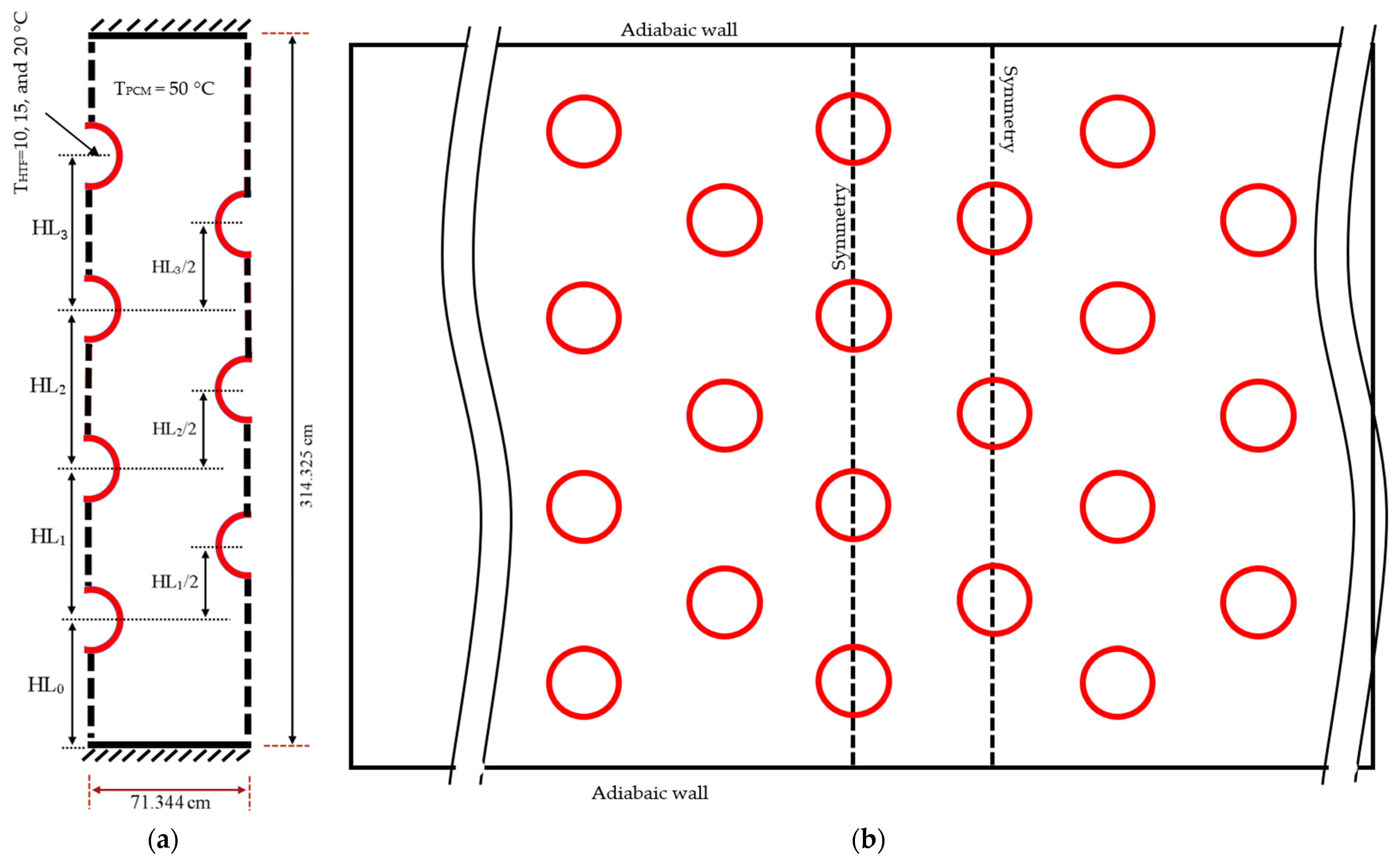
The investigated system is a multi-tube shell-and-tube heat exchanger, incorporating several tubes in a rectangular PCM container.
Figure 1a illustrated the schematic of the proposed heat exchanger incorporating seven tubes in symmetrical conditions from both the left and right sides that could be extended by repeating the pattern in the horizontal direction, and
Figure 1b illustrates the full domain. This assumption can be considered with a long width for the heat exchanger. The heat exchanger’s upper and lower walls are adiabatic to eliminate the impact of environmental conditions with no-slip boundary conditions. Different tubes’ wall temperatures of 10, 15, and 20 °C are considered for the solidification process, while the initial temperature of the PCM is equal to 50 °C. Gravity is considered in the vertical direction toward the bottom of the heat exchanger. It should be noted that the system is studied in two-dimensional conditions due to the high computational cost of 3D simulations. It should be noted that this assumption is meaningful considering a long length of the heat exchanger ignoring the wall effects.
The nominal diameter of the tube (D) is 12.7 mm (0.5 in) with an outer diameter of 15.875 mm, which is one of the standard sizes of copper tubes in heat exchangers. The height of the shell is assumed to be 314.325 mm, and the width of each repeated section is considered to be 71.344 mm. As shown in
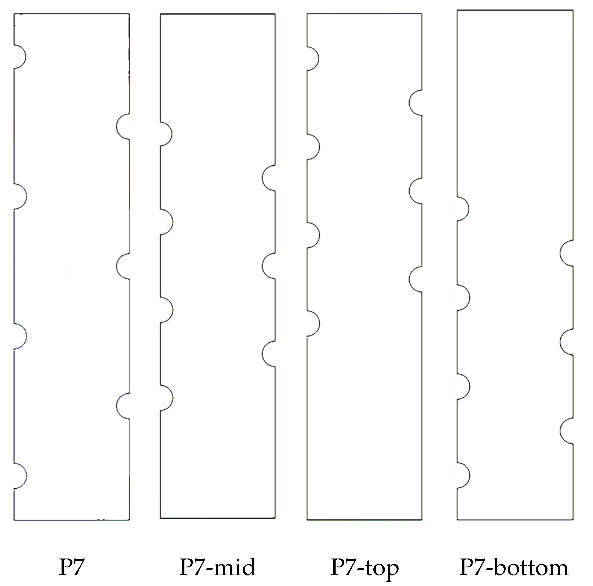
Figure 1a, for the uniform distribution of the pipes, it is assumed that the distance between two pipes that are next to each other on the left wall and the adjacent pipe on the right wall is constant. In addition, the tubes on the right-hand side of the shell are located at the center line of the two adjacent tubes on the left-hand side wall. In other words, the centers of these pipes generate an equilateral triangle for the uniform arrangement of the pipes. The reason for using a staggered array of the pipes is a better and more uniform distribution of the heat sinks (pipes with low temperature) in the heat exchangers, considering a constant number of the tubes. Thus, during the solidification process, a heat sink can fill the gap between the two adjacent pipes in the vertical direction, which can help improve the solidification rates of the heat exchanger. It should be noted that different arrangements are defined to evaluate the effect of natural convection in the proposed shell and tube heat exchanger, which are presented later in the results and discussion sections.
RT-35 is used as the PCM in this study, of which the thermo-physical properties are presented in
Table 1. The density is assumed to be constant because the specific mass of the PCM is contained in the same volume (constant mass and constant volume), and then the density is constant even during the solidification process.
4. Numerical Process
ANSYS-FLUENT software was employed to solve and analyze the governing equations applying the SIMPLE algorithm with PRESTO and QUICK methods to discretize the momentum and energy equations, respectively. The convergence criteria are set to 10−4 for continuity and 10−6 for the momentum and energy equations. Furthermore, it should be noted that different grids and sizes of time-step were also performed to obtain the results independently from the grid and time step size. It should be noted that due to transient analysis of the phase-change problem, the convergence of all the governing equations at each time step should be checked and satisfied for different grid sizes with the given time steps which are performed in this study.
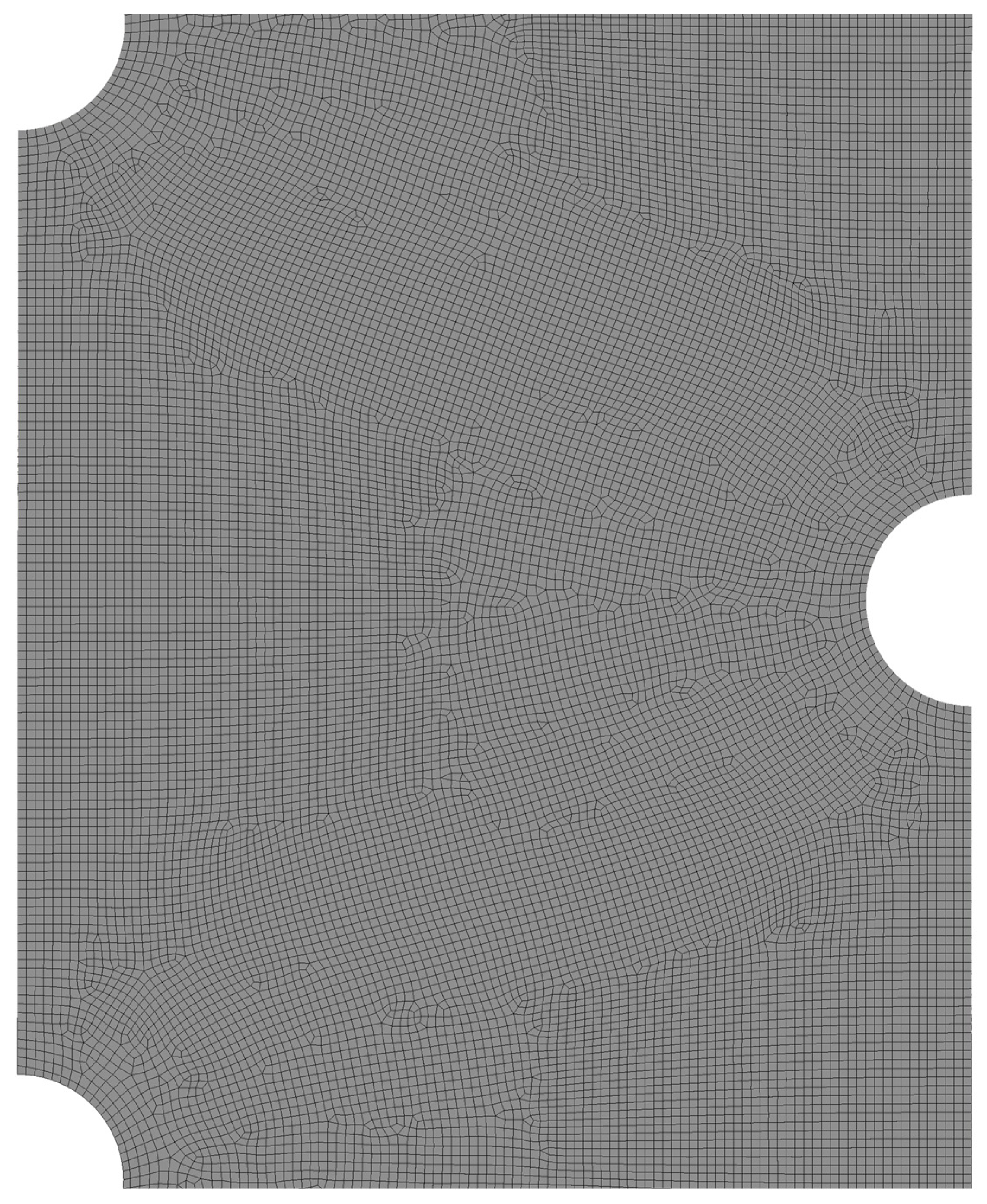
The heat recovery or solidification rate over 16 h was considered as the criteria to find the mesh independently from the number of cells and size of time step. First, different node numbers of 35,122, 52,682 and 105,364 are evaluated considering a time step size of 0.2 for the case with a uniform distribution of the tubes. The results show that the average solidification rate is 53.43, 52.89, and 52.74 for the system with 35122, 52,682, and 105,364 nodes, respectively. Therefore, the mesh with 52,682 nodes is selected for further analysis since the difference in the solidification rate between this case and the case with 105,364 nodes is less than 0.5%.
Figure 2 shows the mesh of the selected case for the middle part of the domain. It should be noted that a uniform mesh is generated in all of the domains considering an edge sizing of 0.66 mm for all the walls of the domain. Different time step sizes of 0.1, 0.2, and 0.4 s are also studied to find the results independently from the size of the time step for the selected mesh. The results showed almost similar solidification rates of 53.01, 52.89, and 52. 55 for different sizes of time steps, and therefore the size of the time step was also selected as equal to 0.2 s. It should be noted that for each simulation, a high spec PC was used using four CPUs in parallel with a base speed of 2.39 GHz. For the case with uniform distribution of the tubes, the simulation of the solidification process for 16 h took 43 h and 29 min.
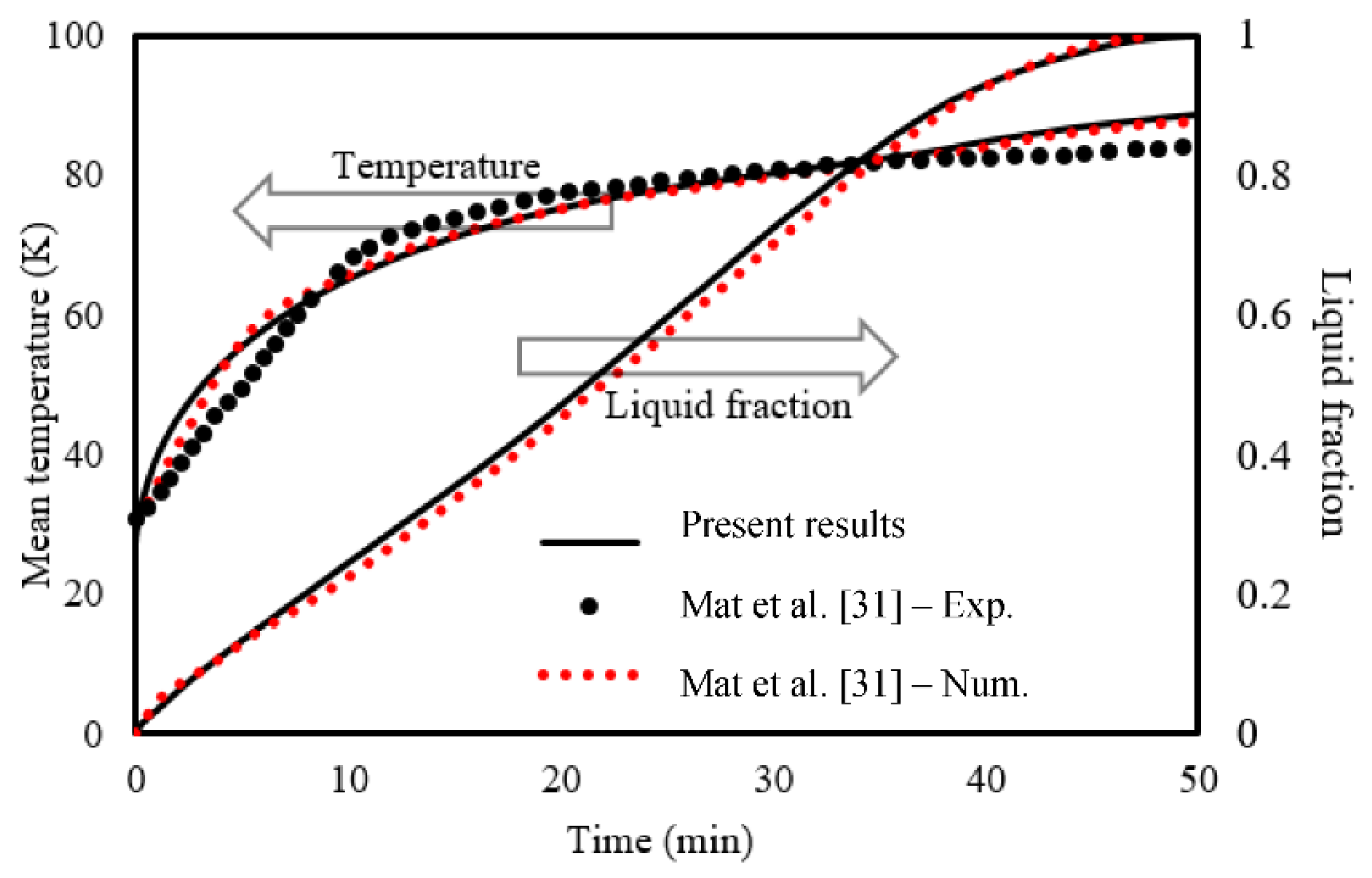
The investigation of Mat et al. [
69] was regenerated to verify the employed numerical simulation in the present study for a phase-change problem. Mat et al. [
69] examined a finned-type dual-pipe LHS numerically and experimentally using organic PCM. The comparison is illustrated in
Figure 3 between the numerical and practical results of the mean temperature and the numerical data of liquid fraction belongs to the study of Mat et al. with the present numerical study, which shows an excellent agreement.
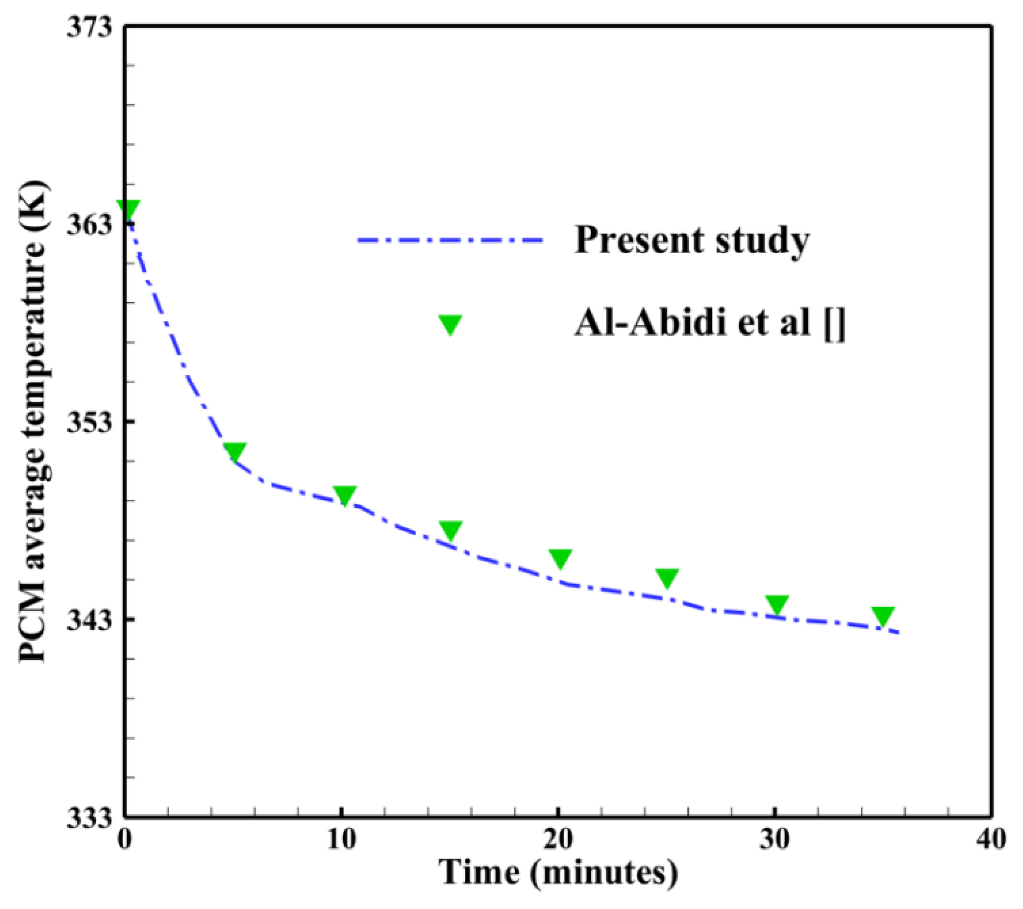
To validate the accuracy during the solidification process, the present study is compared with the experimental work of Al-Abidi et al. [
15]. They investigated the PCM temperature variation in a triple-tube PCM heat exchanger with fins. As observed in
Figure 4, the comparison of the PCM average temperature of the present study are in good agreement with the experimental study of Al-Abidi et al. [
15] showing the accuracy of the present model for the solidification process.
6. Conclusions
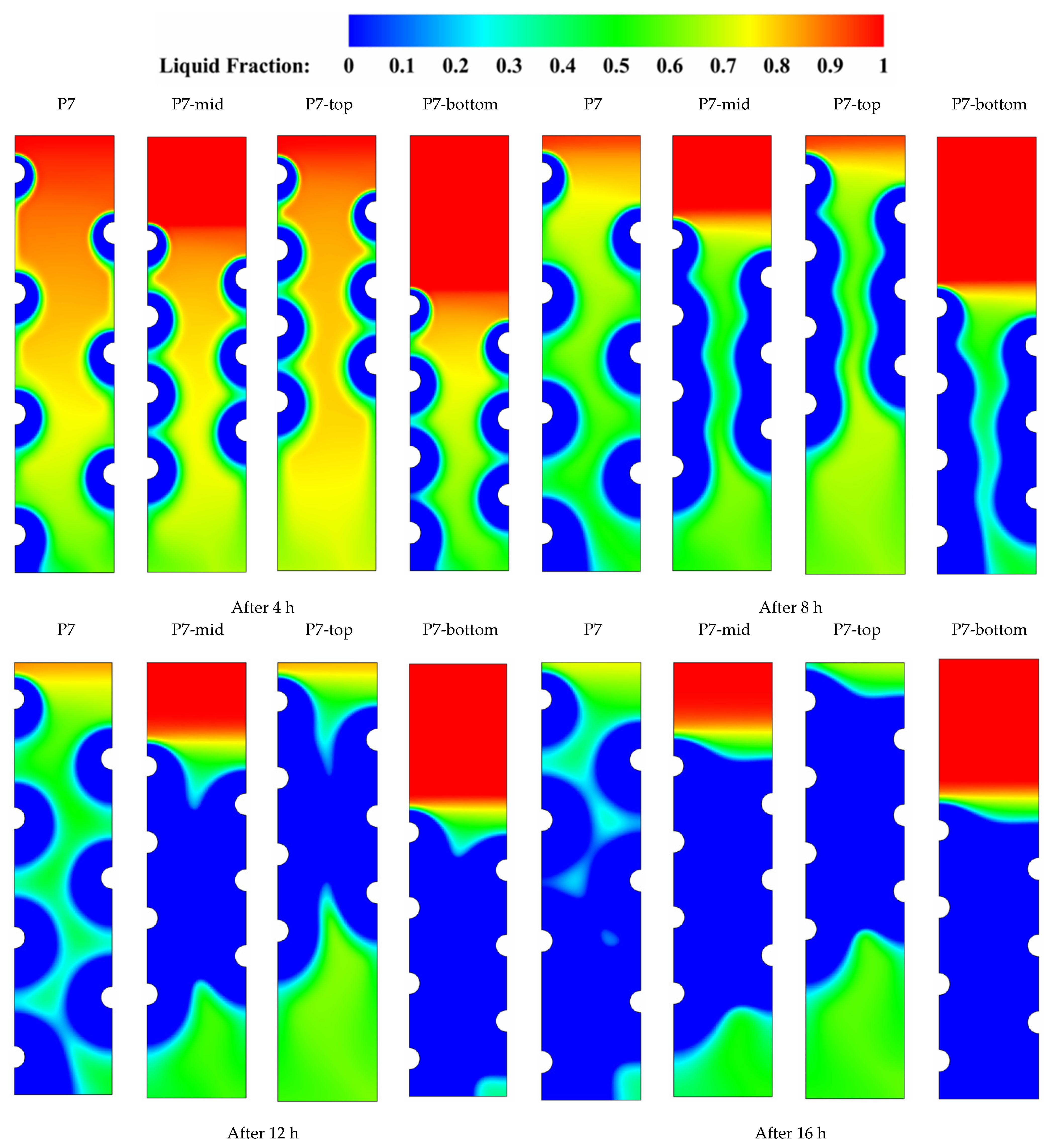
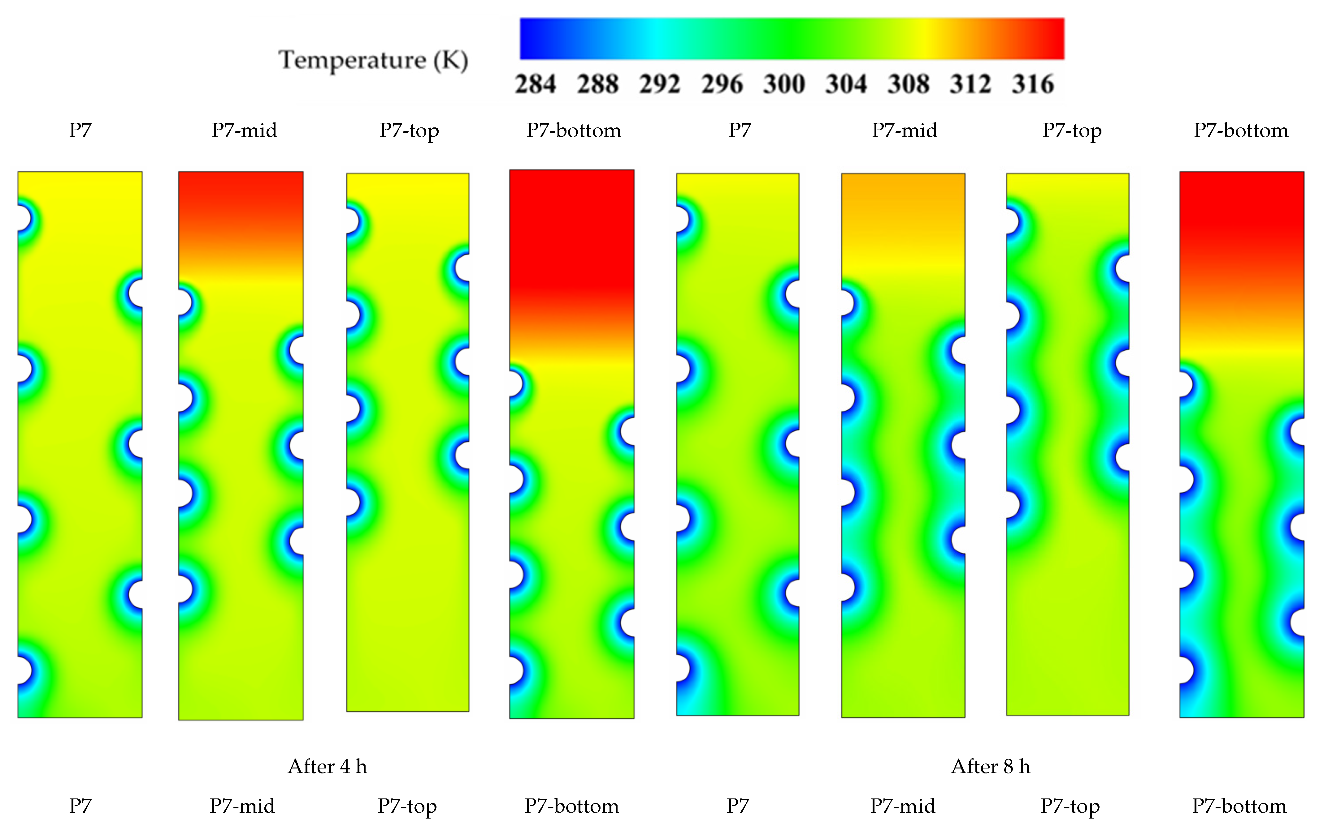
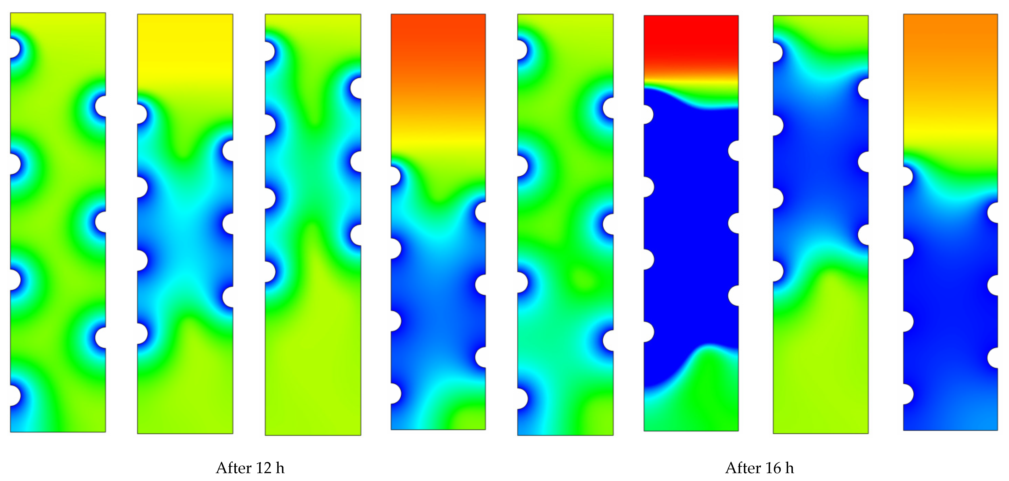
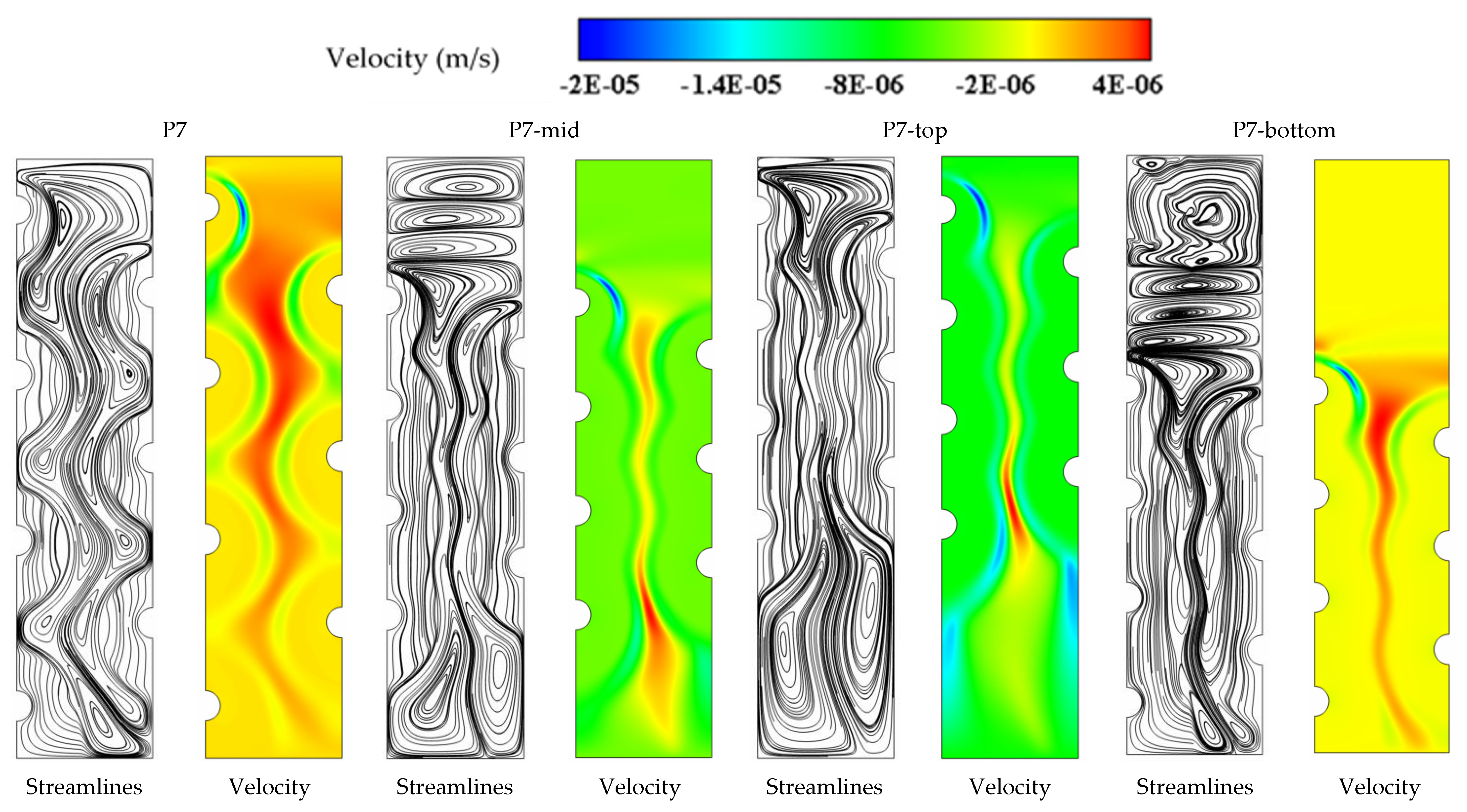
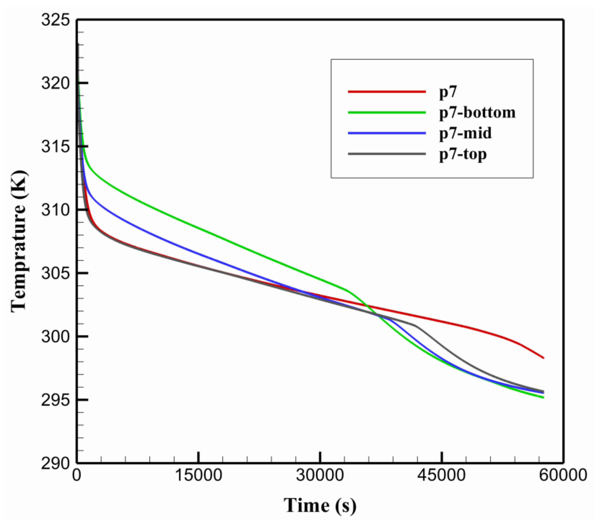
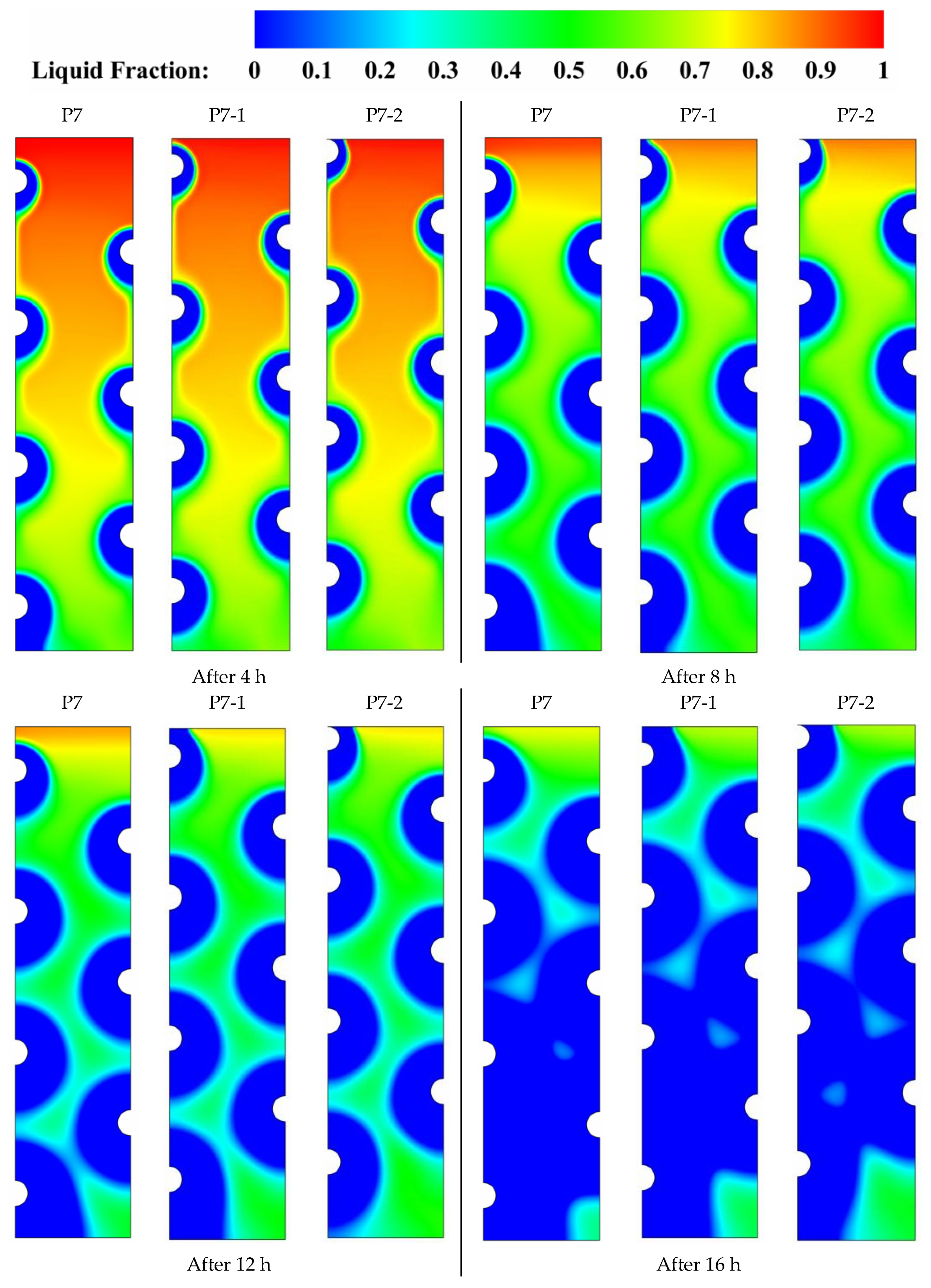
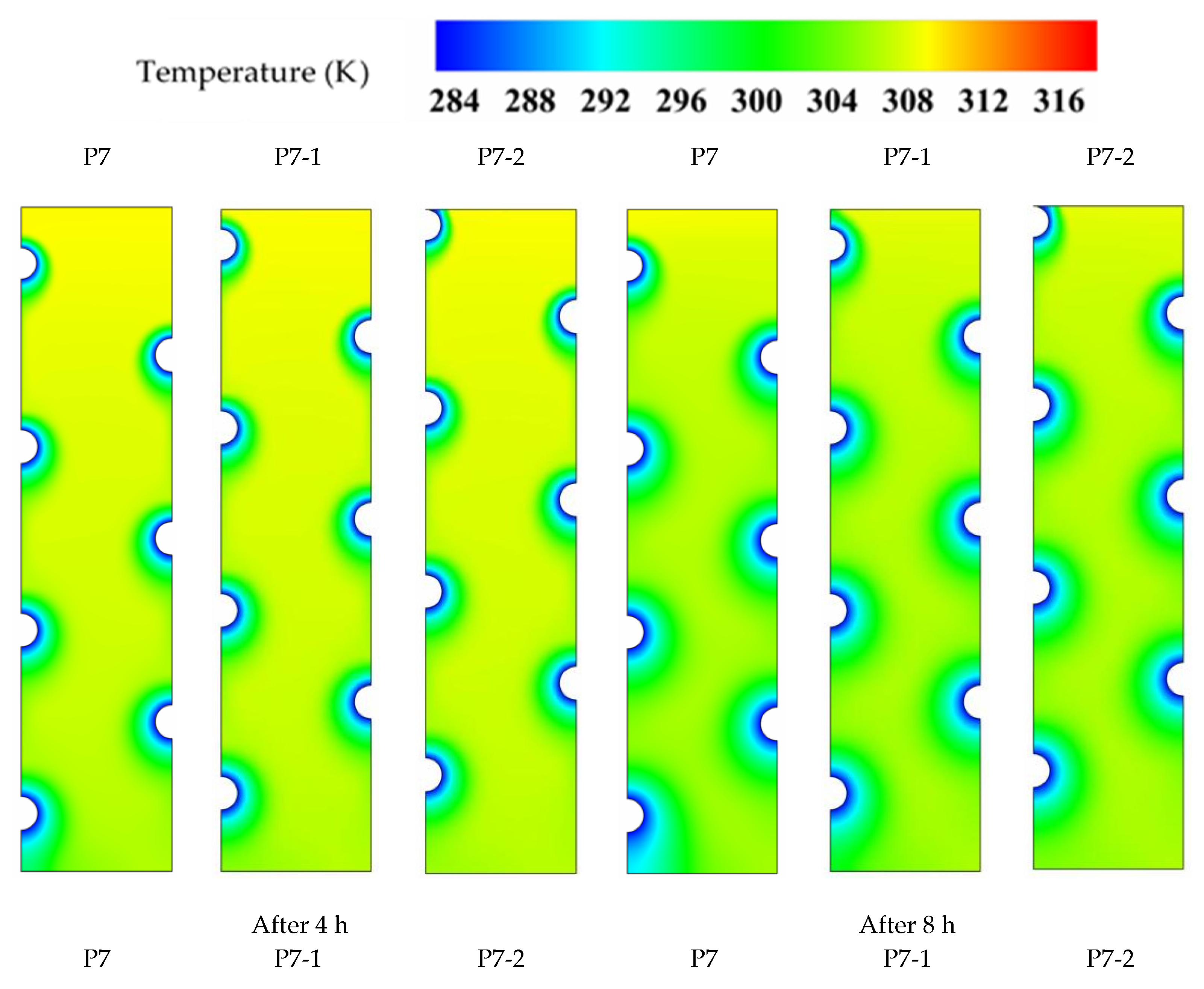
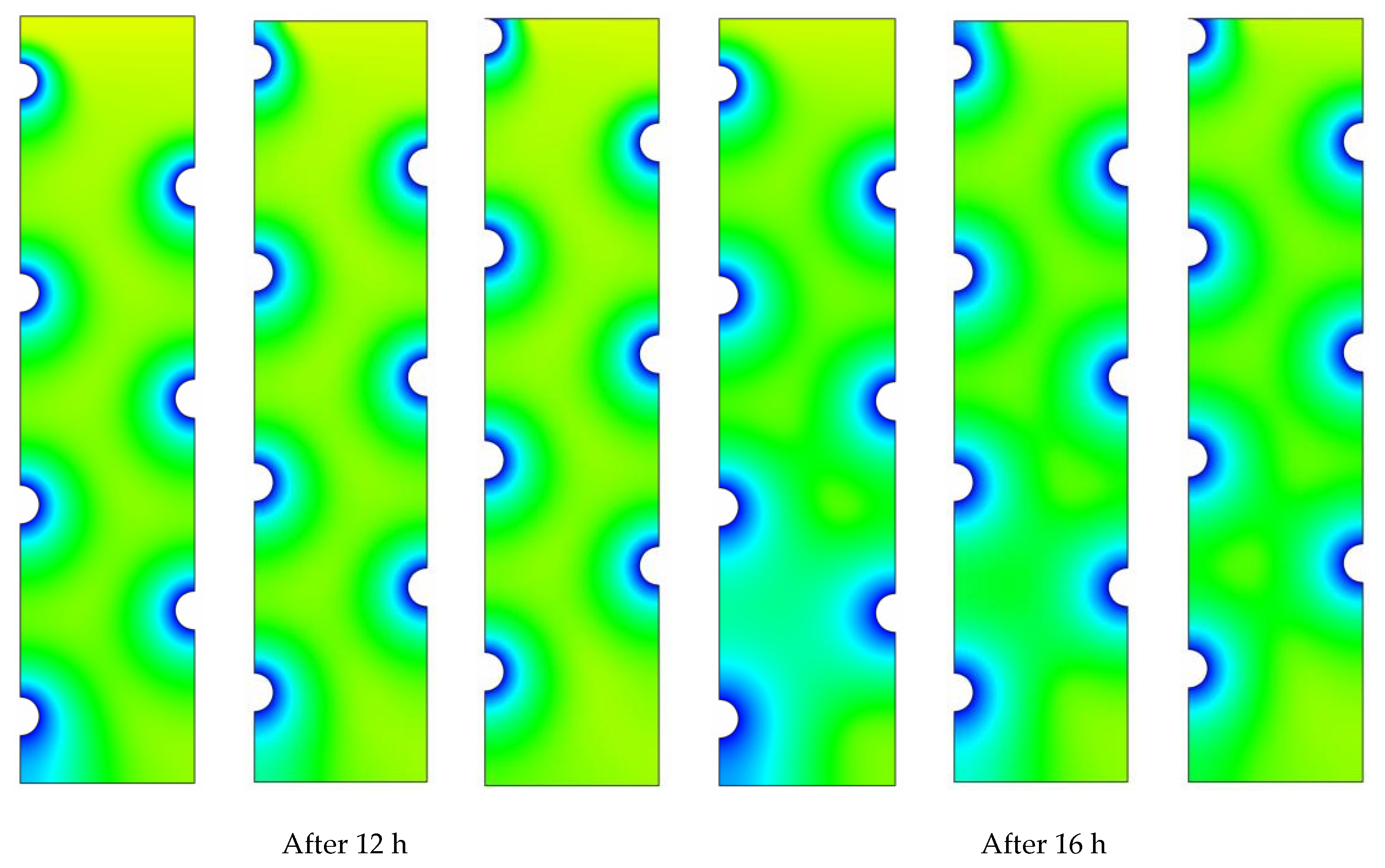
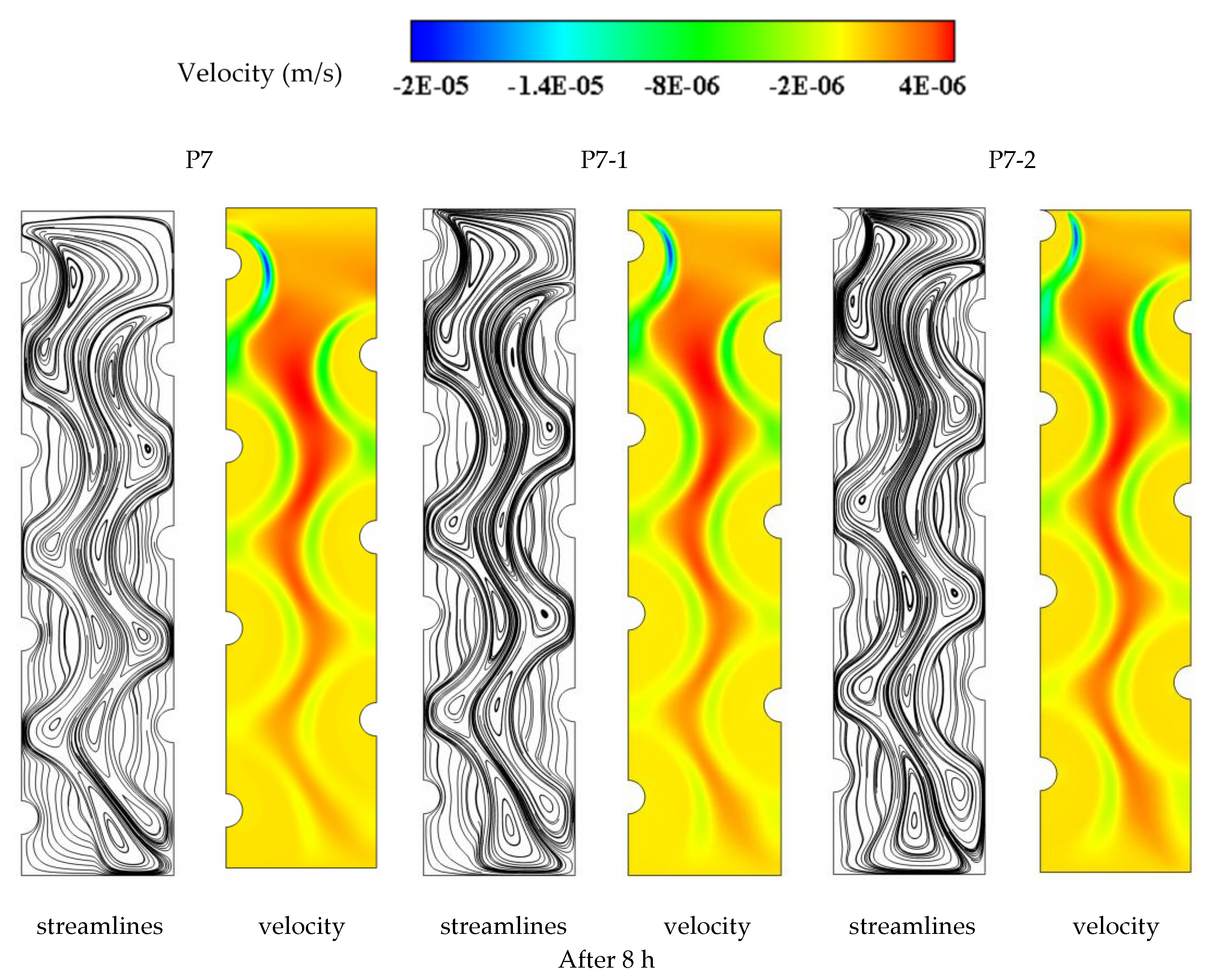
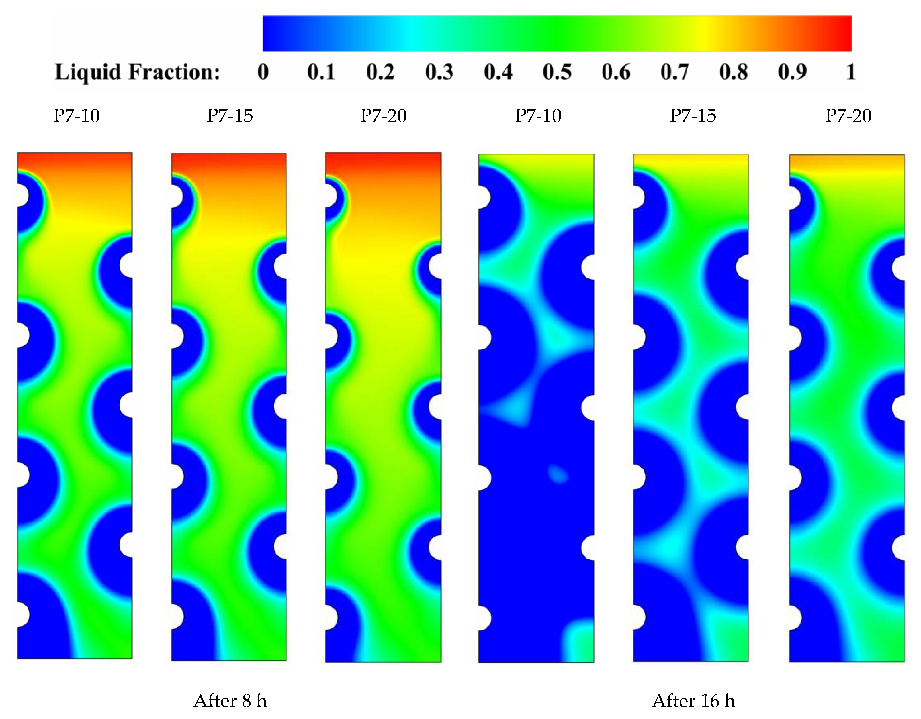
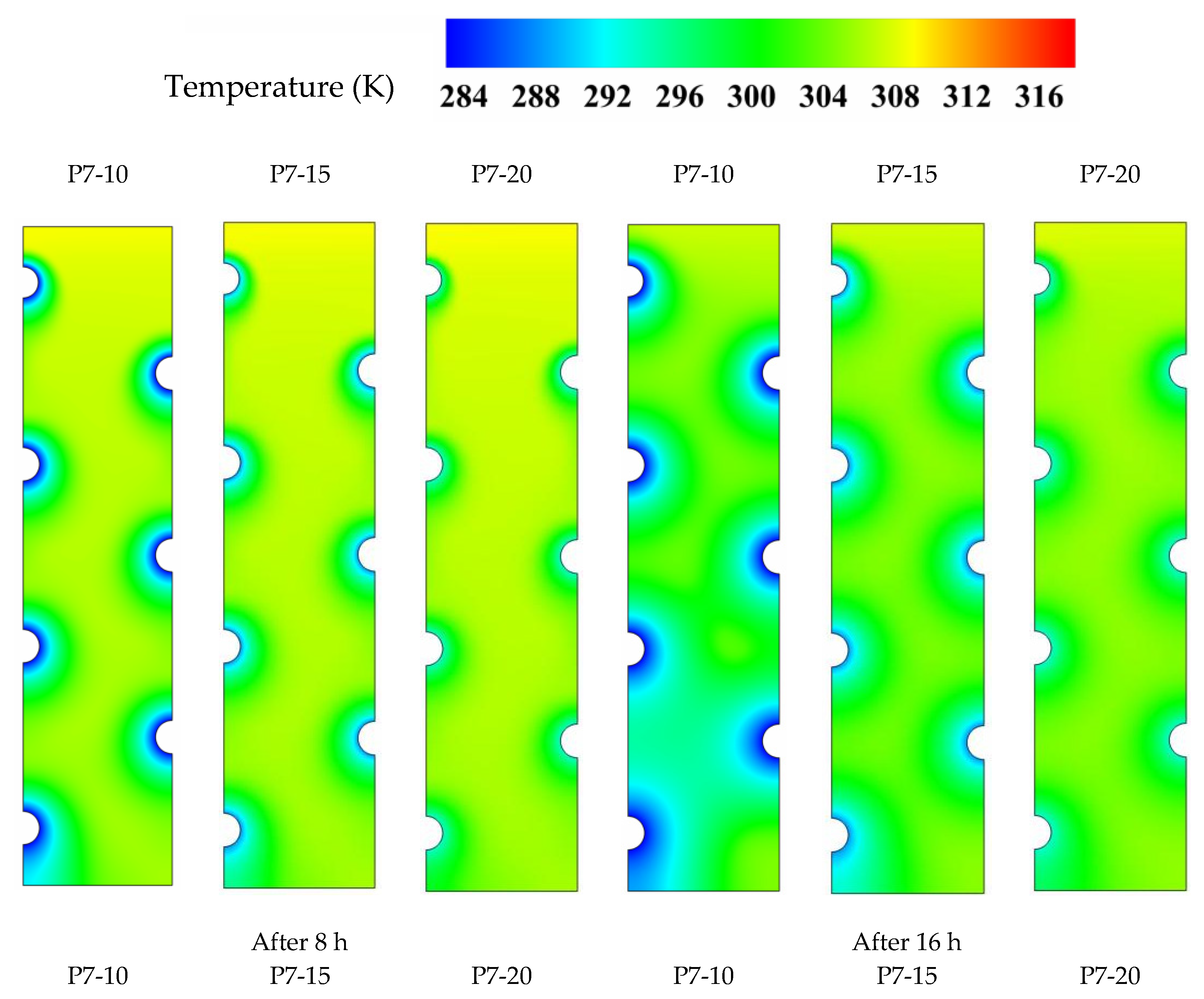
A geometrical model of an LHTES system cooled by HTF channels was analytically examined. The design of the LHTES contained seven HTF channels distributed in different locations in the system for different cases, including uniform distribution of the tubes as well as non-uniform distribution, i.e., tubes concentrated at the bottom, middle, and the top part of the shell. The effect of the channels’ positions on the solidification process in the LHTES system was referred to, utilizing the development of the solid part, solidification maps, streamlines, and isotherms. It should be stated that such an enhancement is achieved without extra costs, since no extra material should be used in the manufacture of an LHTES system. Changing the uniform distribution of the tubes reduces the heat removal rate from 52.89 W to 14.85 W, 22.05 W, and 24.55 W when the tube placements are altered to be clustered at the bottom, middle, or top of the domain, respectively. The solidifying time is reduced from 110,775 s to 99,304 s and 100,488 s to provide time savings of about 11% and 9% when the tube placement is altered from the base case (P7) to the new cases (P7-1 and P7-2), respectively. The heat removal decreases with increasing the inlet temperature of the HTF, whereas it reduces by 7.5%, and 23.7% when the inlet temperature of the HTF increases from 10 °C to 15 °C and 20 °C, respectively. The current work states that special attention should be paid to the arrangement of the tubes as it enhances the discharging process focusing natural convection effect in TES. The distance between the channels could be an additional important geometrical factor, as it essentially could control initial solidified regions and the interface of general movement flows. The study of the space between the channels could be a topic for future studies.


 ,
, 


