Article

Experimental Investigation on Intermittent Operation Characteristics of Dual-Temperature Refrigeration System Using Hydrocarbon Mixture

School of Energy and Power Engineering, Xi’an Jiaotong University, 28 Xianning West Road, Xi’an 710049, China
*
Author to whom correspondence should be addressed.
Energies 2022, 15(11), 3990; https://doi.org/10.3390/en15113990
Submission received: 18 April 2022 / Revised: 20 May 2022 / Accepted: 25 May 2022 / Published: 28 May 2022
(This article belongs to the Section J: Thermal Management)

Abstract

:
An experimental rig of a zeotropic mixture separation condensation-based dual-temperature refrigeration cycle is built and the mixture R290/R600a is used as the refrigerant. Compared with a conventional cycle, the proposed refrigeration system demonstrates its application advantages under an on–off operation mode. Furthermore, the on–off periodic operation behaviors of this refrigeration system are experimentally investigated. The influence of a different refrigerant charge, a refrigerant mass fraction, a throttling valve opening, and ambient temperature are explored to evaluate the cyclic operation characteristics. The results reveal that the compressor average power for the duration of the compressor startup increases and the compressor duty cycle first declines then increases with the rise of the refrigerant charge. The average compressor during an on-period decreases from 104.5 W to 79.2 W and meanwhile the compressor duty cycles fluctuates between 72.1% and 96.9% as the R600a-charged concentration increases from 30% to 70%. The average power of the compressor during the on-period and the duty cycle are also sensitive to the freezer valve opening variation. Thus, the minimum energy consumption of 1.60 kWh·24 h−1 is achieved at the refrigerant charge of 300 g, a R600a-charged mass fraction of 50%, and a freezer throttling valve opening of 10%. A higher ambient temperature deteriorates heat transfer during condensation and increases the cabinets’ heat load, the compressor duty cycle, and eventually affects the daily power consumption. Generally, the present study offers an in-depth insight of cyclic operation characteristics of a separation condensation-based hydrocarbon mixture dual-temperature refrigerator under two parallel evaporators’ concurrent cooling process.

1. Introduction

Domestic refrigerators have become the most indispensable household electric appliance for food storage. However, refrigerators are categorized as the principal energy consumer due to its operation throughout the day. According to statistics, refrigerators contribute to approximately 6% of the electricity worldwide [1]. Thus, many efforts have been advocated to improve refrigerators’ energy using efficiency including refrigeration cycle modification, refrigerant substitution, and system component optimization [2,3,4]. From the published literatures, refrigerant substitution has become a research hotspot in refrigeration systems [5,6]. In detail, hydrocarbon blends provide appropriate techniques to improve system performance owing to zeotropic mixtures’ composition shift and temperature glide characteristics [7,8,9]. Actually, the utilization of R290/R600a in refrigerators is the popular choice amongst the hydrocarbon zeotropic mixtures owing to its energy saving benefit and environmentally friendly feature [10,11,12,13]. Yan et al. [14] proposed an auto-cascade refrigeration system using R290/R600a for application in domestic refrigerators. The numerical results indicated that a novel cycle can improve the coefficient of performance (COP) by 7.8–13.3% and enhance the volumetric refrigeration capacity by 10.2–17.1% compared with a conventional cycle. Liu et al. [15] adopted an ejector in the domestic refrigerator using R290/R600a to achieve expansion loss recovery and system performance improvement. The energetic and exergetic analysis results showed that the presented cycle can lift COP and volumetric cooling capacity by 16.71% and 34.97%. Fang et al. [16] integrated the separation condensation and parallel compression methods to propose a modified dual-temperature refrigerator cycle using R290/R600a. The simulation results revealed that the presented system can enhance both COP and exergy efficiency by 30.4%. The research provided an effective technique to improve system performance in a refrigerator–freezer. Yu and Teng [17] experimentally investigated the refrigeration performance and feasibility of R290/R600a as an alternative refrigerant to R134a in a refrigerator and found that the 24-h electricity consumption can be decreased by up to 10.9%. Fatouh and Kafafy [18] evaluated the performance of a hydrocarbon mixture as drop-in replacement to R134a in household refrigerators. They concluded that the refrigerator with the hydrocarbon blend with 60% propane showed a 2.3% higher COP and an 11.1% lower pressure ratio compared with the original refrigerator. Yoon et al. [19] experimentally explored the system performance of household refrigerators. The results proved that a R290/R600-based Lorenz–Meutzner cycle can reduce the energy consumption by 11.2% in comparison with a bypass system using R600a. Jwo et al. [20] discovered that the utilization of R290/R00a (50%/50% by mass fraction) reduced the energy consumption by 4.4% compared with R134a in a 440 L capacity household refrigerator. Wongwises and Chimres [21] indicated that R290/R600a can be an appropriate alternative to R134 in household refrigerators with a lower energy consumption. Rasti et al. [22] performed experimental research on the utilization of R290/R600a in a R134a domestic refrigerator and discovered that the duty cycle and daily power consumption were reduced by 13% and 5.3%, respectively. Ozsipahi et al. [13] experimentally explored the system performance of household refrigeration using R290/R00a. They concluded that the utilization of R290/R00a could improve the COP by about 10–20% in comparison with R600a as a baseline. Chen et al. [23] presented an ejector-enhanced dual-temperature refrigerator system using R290/R600a and evaluated the system performance through thermodynamic analysis. The results indicated that the proposed system showed a 23.1% and a 22.9% enhancement in COP and exergy efficiency, respectively. Lee et al. [24] experimentally evaluated the performance of a domestic refrigerator with R290 and R600a as drop-in replacements to R134a. They concluded that the R290/R600a (55%/45% by mass fraction) system reduced the energy consumption by 12.3% and improved the cooling speed by 28.8% compared with the system using R134a.
Experimental studies on the power consumption and duty cycle of domestic refrigeration systems were conducted to explore the system performance during the on–off operation cycle [10]. Abou-Ziyan and Fatouh [25] conducted experimental investigation on a hydrocarbon mixture as the substitute of R134a in a household refrigerator. The experimental results indicated that the refrigerator using R290/R600a/R600 (60:26.6:13.4% by mass) could save about 36.8% of power consumption in comparison with an R134a system under on–off cyclic operation. He et al. [26] explored the application possibility of an R290/R600a mixture in an R134a chest freezer through experimental tests. They discovered that the system with R290/R600a (93.75%/6.25% by weight) reduces the power consumption by 27.5% compared with that with R134a. Furthermore, the system using R290/R600a decreased the on–off ratio from the baseline data 39.5% to 33.8% in terms of cyclic operation behavior. Mohanraj et al. [27] explored the cycling running performance of a 220 L refrigerator with R290/R600a to substitute R134a. The test results demonstrated that R290/R600a (45.2%/54.8% by weight) exhibited an 11% lower energy consumption and a 13% lower duty cycle.
In our published literature [28], the system performance of a modified dual-temperature refrigeration system with R290/R600a was evaluated by energetic and exergetic analysis. The proposed refrigeration system adopted two parallel evaporators to achieve a dual-temperature refrigeration effect through a zeotropic composition shift and separation condensation. The simulation results demonstrated its system performance improvement advantage over the conventional refrigeration cycle. Furthermore, the previous work also revealed the feasibility of this refrigeration cycle for applications in domestic refrigerator-freezers. However, the most popular way to maintain cooling temperature in domestic refrigerators is through on-off operation control by a thermostat. Actually, the on-off cyclic running mode occurs in the most lifetime for refrigerators. The power consumption, duty cycle, and compressor power during a compressor’s on/off period are the key parameters to evaluate the system performance and cyclic operation features [25]. Few literatures focus on complete cyclic characteristics to evaluate the dynamic behaviors of refrigerators using hydrocarbon mixture under a permanent cyclic operation mode. In particular, the system performance of the proposed separation condensation based dual-temperature refrigeration system using a zeotrope during actual cyclic operation needs to be further explored to boost its application in refrigerators. Thus, it is necessary to investigate the cyclic operation characteristics of separation condensation-based hydrocarbon mixture dual-temperature refrigeration system. An experimental rig of the proposed refrigeration system utilizing R290/R600a was built. The complete cyclic operation characteristics including duty cycle, compressor power, energy consumption, and mass flow rate need to be explored. Furthermore, the effect of different refrigerant charges, refrigerant compositions, throttling valve openings, and ambient temperature on intermittent operation characteristics should be evaluated. The present work can offer experimental support for practical applications of the proposed cycle. Furthermore, it promotes the development and an in-depth understanding of the modern refrigeration system designs with zeotropic mixture under actual cyclic operation.

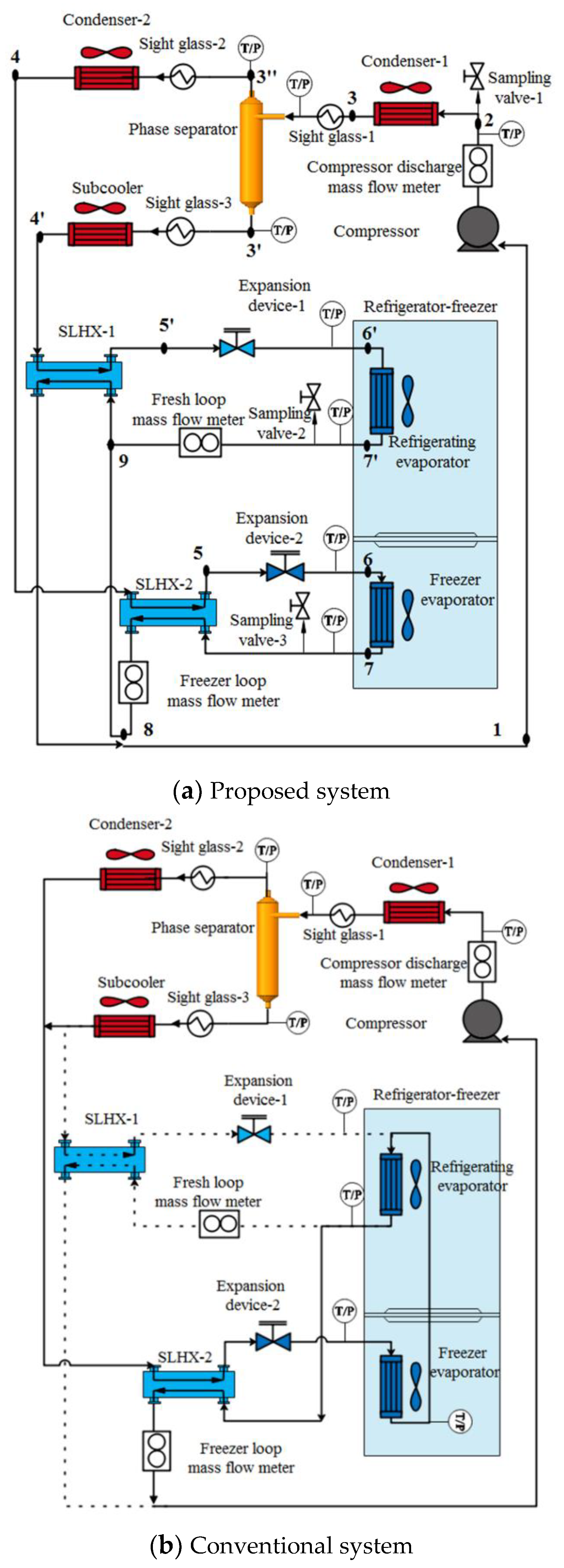
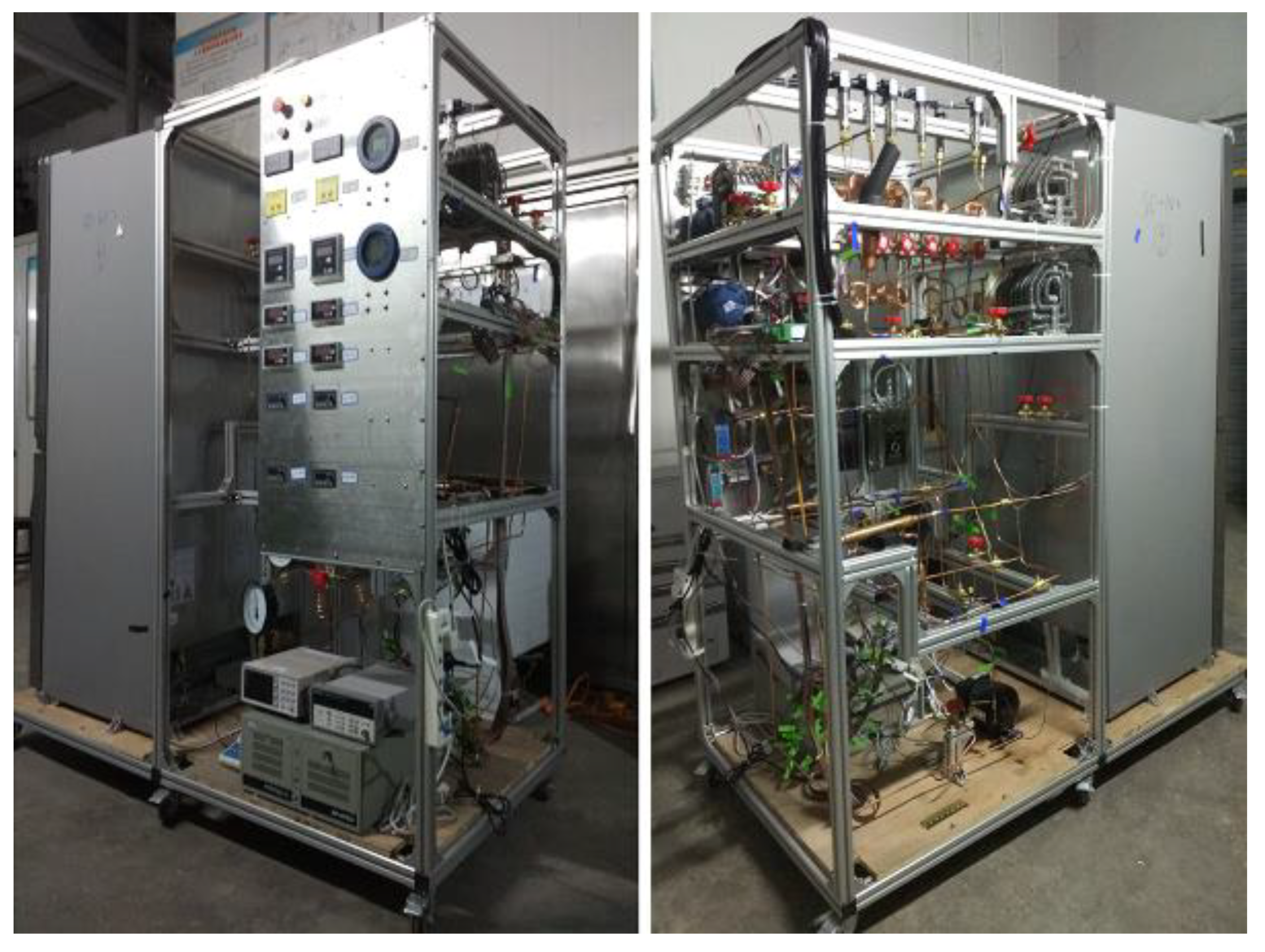
2. Experimental Equipment and Testing Procedure

Figure 1a illustrates the schematic of proposed dual-temperature refrigeration system employing zeotropic mixture R290/R600a. The primary components of this refrigeration system include a hermetic reciprocating compressor, two air-cooled condensers, an air-cooled subcooler, two liquid-line/suction-line heat exchangers (SLHX-1 and SLHX-2), a vapor–liquid phase separator, two throttling valves, and two fin-tube evaporators (one is located in in the fresh chamber and the other is installed in the freezer chamber). The main thermodynamic properties of zeotropic mixture components are given in Table 1 [29,30]. The corresponding pressure-specific enthalpy diagram is illustrated in Figure 2. The dots in Figure 1 stand for the corresponding refrigerant state in Figure 2. Moreover, the solid lines in Figure 1 indicate actual refrigerant flow stream and the dot lines in Figure 1b means the refrigerant flow stream is closed.
The detail working procedure of this dual-temperature refrigeration cycle using R290/R600a has been introduced in our previous work [28,31], and is not presented here for simplicity. According to Figure 1a and Figure 2, the freezer loop and refrigerating loop operate at simultaneous cooling modes. Owing to composition shift in phase separator, the more volatile component R290 flows into the freeze loop and correspondingly more R600a enters refrigerating loop. Consequently, the two parallel evaporators reveal different evaporating temperature at identical evaporation pressures. This contributes to the higher compressor suction pressure and better system performance. Moreover, the zeotropic mixture’s temperature glide feature in evaporation process also benefits the system performance because of heat transfer temperature difference reduction effect. Generally, the previous theoretical study has demonstrated the advantages of proposed system over conventional refrigeration system.
The previous work [28] mainly concentrates on theoretical study to manifest the advantage of proposed refrigeration system over conventional cycle in terms of energy and exergy aspects. To further explore the application potential and operation characteristics, the experimental rig of separation condensation based dual-temperature refrigeration system employing R290/R600a is built as shown in Figure 3. A hermetic reciprocating compressor with 5.8 cm3 displacement was utilized in the presented refrigeration system. For high pressure side heat exchangers’ configuration, three fin-tube type heat exchangers were used in condenser-1, condenser-2, and subcooler. A cyclone vapor-liquid phase separator with the internal volume of 0.4 L was adopted to achieve phase and composition separation effect. The two-phase refrigerant from condenser-1 enters the vapor–liquid phase separator in tangential direction. The copper tube at vapor outlet was inserted into the separator by 10 cm to prevent liquid splash and escape from the upper exist. Two double-pipe type heat exchangers were employed as liquid-line/suction-line heat exchangers in freezer loop and refrigerating loop, respectively. A manual modulation throttling valve (manual mechanical needle valve) was adopted to adjust the evaporation temperature and refrigerant mass flow rate to achieve cooling capacity control. The refrigerating evaporator as well as freezer evaporator are both plain fin-tube heat exchangers and installed in corresponding cabinets. The tested prototype as shown in Figure 4 is a domestic refrigerator with freezer chamber volume of 166 L and fresh chamber volume of 262 L. The specifications of main components are summarized in Table 2. The experimental investigation mainly focuses on refrigerating and freezer cooling loops concurrent operation condition. In case of the sudden increase in heat load in freezer cabinet, the freezer evaporator fan speed can be adjusted and the refrigerating fan can be switched off to match the cooling capacity and heat load. All tests were tested inside environmental chamber designed on technical standard of ENISO 15002:2005, as shown in Figure 3. According to Figure 3, there are 4 testing positions (workstations) in environmental chamber. The prototype refrigerator installed with proposed refrigeration system is placed on the No.2 testing position to conduct experiment investigation. The dry-bulb temperature and air humidity of environmental chamber can be maintained within 0–55 °C and 40~80%, respectively, which can meet the test requirement of refrigerators.
T-type thermocouples with ±0.5 °C accuracy were utilized to meter the specific temperature. The temperatures at the top, middle, and bottom of both freezer and refrigerating cabinets are measured, and average values in each cabinet are considered as freezing temperature and refrigerating temperature. The compressor suction and discharge pressures are acquired by pressure transducers with ±0.25% accuracy of the full scales of 0–2 MPa. The refrigerant mass flow rates are measured with Coriolis digital flowmeters with ±0.2% accuracy of 5 kg·h−1 and 10 kg·h−1. The energy consumption of the prototype is obtained by a digital power meter with ±0.2% accuracy. The refrigerant charge amount is evaluated through a high-precision balance with an uncertainty of ±0.1 g. Moreover, the charged refrigerant composition can be adjusted by controlling the charge mass of each component. A data acquisition system based on Agilent 34970 is built to record hydrocarbon mixture mass flow rate, temperature, pressure, and compressor power every 20 s. Main measurement apparatuses and the uncertainties are summarized in Table 3. The test work is carried out at the ambient temperatures of 16, 20, 25, and 32 °C according to the Chinese National Standard GB/T 8059-2016 and the literature [32].
The detailed experiment process in this work is as follows:
(1)
After leakage detection by nitrogen gas, the dual-temperature refrigerator system is thoroughly vacuumed with an evacuating pump to achieve the system absolute pressure under 1.5 kPa before each charged process;
(2)
The high boiling component R600a and low boiling component R290 are charged into the dual-temperature refrigeration system, respectively, at designated mass for each pure component. It is worth mentioning that pure refrigerants are charged by the order of R600a and R290 component to avoid the backward phenomenon;
(3)
The experimental refrigerator must be placed inside the environmental chamber for over 8 h to balance composition distribution before this refrigeration system operation. The prototype in unloaded condition (i.e., without additional thermal load) should operate over 24 h to obtain consecutive on–off cyclic operation mode.

3. Results and Discussion

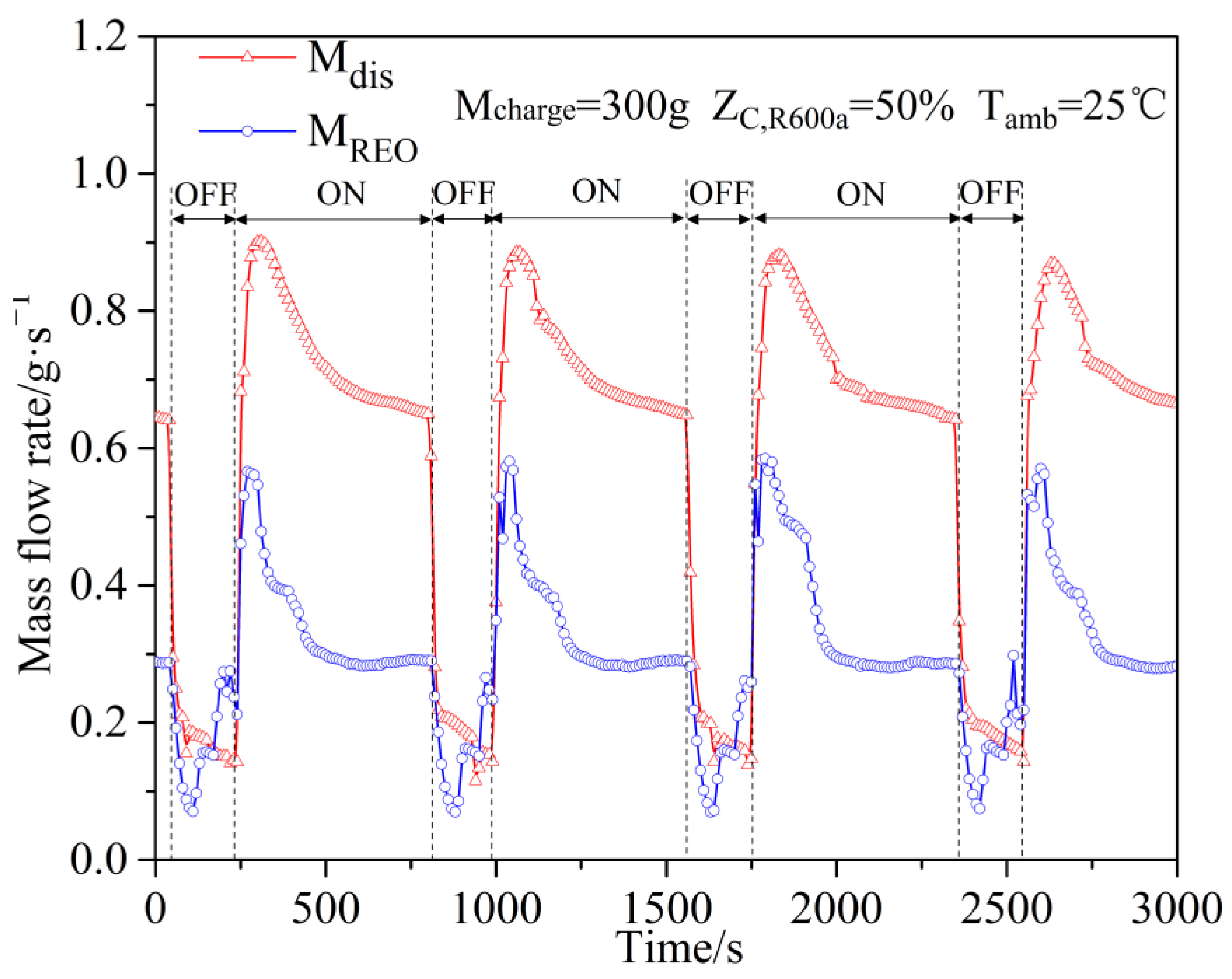
3.1. On-Off Cyclic Operation Features of Zeotropic Mixture Based Dual-Temperature Refrigeration System

The most popular way to achieve cooling temperature in domestic refrigerator-freezers is through on-off cyclic operation control by thermostat. For the experimental prototype, the thermostat is located in the freezer cabinet and the target cooling temperature is pre-set as −18 °C with a hysteresis of 1 °C by the control panel. Under a no-load state condition, the refrigerator has been running for over 24 h to maintain a consecutive on-off cyclic operating state. The system performances of the proposed refrigeration system are compared with those of the conventional cycle. Figure 5 depicts the freezer and fresh cabinet temperature fluctuation for the modified refrigeration system and the conventional cycle during on-off intermittent operation. According to Figure 5, both refrigeration systems can accomplish the target cooling temperature for two cabinets. Clearly, the freezer temperature in the conventional cycle ranges from −17.1 °C, during the off-period, to −18.6 °C during the on-period. Correspondingly, the freezer temperature in the modified refrigeration system fluctuates between −19.2 °C and −17.0 °C during the on and off operation period. Considering that the temperature oscillating phenomenon occurs in both cooling cabinets, innovative control logic such as Artificial Neural Networks [33] can be a better solution to further enhance the system performance.
Figure 6 depicts the variation tendency of compressor power at the on-off cyclic running state for both refrigeration systems. It should be pointed out that the average compressor power of the proposed refrigeration system during the on-period is 91.2 W and 23.2% higher than that of conventional cycle. This phenomenon lies in the mass flow rate increase at the compressor suction port for the proposed refrigeration system. Furthermore, the presented system can reduce the compressor duty cycle by 21.2% compared with conventional refrigeration cycle. Consequently, the refrigerator installed with the proposed refrigeration cycle has the daily power consumption of 1.60 kWh·24 h−1, 3% lower than that of conventional cycle. Thus, the proposed refrigeration system demonstrates its application advantages in the refrigerator, and this also provides experimental validation and support for previous theoretical study.
The following part of this work mainly concentrates on the cyclic operation characteristics of the proposed refrigeration system. Figure 7 illustrates the evaporation temperature fluctuation trend in both the refrigerating loop and the freezer loop. It can be observed that the evaporation temperature difference between the freezer and the refrigerating evaporation temperature fluctuates from 2.1 °C and 6.5 °C under cyclic operation conditions. This fact results from different composition steams in these two loops because of the composition shift phenomenon in the phase separator. Actually, the refrigerant compositions are quite different for these two parallel loops according to our previous experimental work [28]. The lower boiling point component R290 enters the freezer loop and achieves a lower evaporation temperature at the same evaporation pressure. Moreover, this temperature difference reaches the peak at the end of the compressor on period. The refrigerant superheating degree at the freezer evaporator outlet is 0~4 K during the compressor’s running period. Correspondingly, the refrigerant superheating degree at the refrigerating evaporator exit is 9.7 K on average. Figure 8 shows the compressor suction and the discharge pressure variation trend during the on-off operation at a given condition. The compressor discharge pressure oscillates from 0.82 MPa at the end of the off-period to 0.65 MPa at end of the on-period. The corresponding compressor suction pressure fluctuates from 0.11 MPa to 0.22 MPa. Consequently, the compression ratio shifts from 3.0 to 7.0 because of the on-off duration, which is under the design condition of the compressor.
Figure 9 depicts the refrigerant mass flow rate fluctuation at the compressor’s discharge exit Mdis and the fresh evaporator outlet MREO. Within 50 s after the compressor startups, the mass flow rates rapidly reach summit values of approximately 0.9 g·s−1 and 0.58 g·s−1 for the compressor discharge loop and the refrigerating loop, respectively. The main reason is to swiftly accomplish refrigerant migration and build the pressure difference between high- and low-pressure sides. Subsequently, the refrigerant mass flow rate of the total circuit Mdis decreases continuously until the end of the on-operation period. Correspondingly, the refrigerant mass flow rate in the refrigerating loop MREO decreases from 0.58 to 0.30 g·s−1 and maintains the status quo during the later stage of the on-operation period. There is an interesting phenomenon that MREO fluctuates within 0.08 to 0.30 g·s−1 at the off-operation stage. This is due to the comprehensive effect of the compressor shutdown and refrigerant migration from the condenser.

3.2. The Effect of Refrigerant Charge on Intermittent Operation Characteristics

As is well known, the refrigerant charge is an important factor to affect the system performance for the refrigeration cycles. Thus, the effect of the refrigerant charge on the intermittent operation characteristics is investigated for a separation condensation-based refrigeration system. Figure 10 shows the compressor power fluctuation during the on–off intermittent operation period for different refrigerant charges under the given condition: Tamb = 25 °C and ZC,R600a = 50%. It can be seen that all the cases can achieve consecutive on-off operation conditions when the charge amount changes from 280 g to 340 g. Clearly, the compressor power jumps to the peak value within 50 s after the compressor startups, which is in accordance with the variation trend of mass flow rate in Figure 9. Furthermore, the average compressor power increases from 93 W to 103 W during the on-period as the refrigerant charge ranges from 280 g to 340 g. The major cause is that the refrigerant mass flow rate through the compressor rises due to the charge amount increment. Correspondingly, the compressor duty cycles are 84.1%, 73.2%, 76.2%, and 72.1%, respectively, at refrigerant charges 280 g, 300 g, 320 g, and 340 g. The daily power consumption is used to comprehensively estimate the system performance at the cyclic operation stage. Figure 11 depicts the daily energy consumption variation trend with the refrigerant charge. As the refrigerant increases from 280 g to 340 g, the daily energy consumption firstly decreases from 1.89 kWh·24 h−1 to 1.60 kWh·24 h−1 and then rises to 1.74 kWh·24 h−1 under the general influence of the compressor power and the duty cycle. Thus, there exists the optimal refrigerant charge of 300 g to obtain the lowest energy consumption of 1.60 kWh·24 h−1. It should be noted that the proposed refrigeration system adopts a compressor with a lubricant oil of 300 g. Considering that oil management is a key issue for all refrigeration systems, an oil separator can be adopted to avoid potential oil management problems.

3.3. The Effect of Refrigerant Component Fraction on Intermittent Operation Characteristics

In our previous work [31], the circulation concentration for binary refrigerant always deviates from the corresponding charged concentration. The refrigerant concentration discussed in the following is designated as the charged composition (mass fraction for each component) at the compressor process port. Figure 12 illustrates the compressor suction and the discharge pressure fluctuation with different charged refrigerant compositions under the given conditions: Tamb = 25 °C and Mcharge = 300 g. Apparently, both compressor discharge and suction pressure increases with the increasing concentration of R290. Note that the maximum compression ratio decreases from 8.1 to 6.5 during the compressor-on status as the R600a charged concentration changes from 0.3 to 0.7. The compressor power variation trend during the cyclic operation period is shown in Figure 13. The average compressor power during the on-period decreases from 104.5 W to 79.2 W due to the reduction in the compression ratio and a higher compressor efficiency with the increment of R600a concentration. Correspondingly, the compressor duty cycles are 83.8%, 72.1%, 73.2%, 86.9%, and 96.9%, respectively, when the R600a-charged concentration ranges from 0.3 to 0.7. Thus, R600a-charged concentrations at 40% and 50% mass fraction are considered as the candidates to achieve a lower duty cycle. Furthermore, the daily power consumption also fluctuates with the refrigerant-charged concentration as depicted in Figure 14. The daily energy consumption firstly declines from 2.11 to 1.60 kWh·24 h−1 and then goes up to 1.86 kWh·24 h−1 as the R600a-charged mass fraction increases from 30% to 70%. Although the compressor operation time at ZC,R600a = 50% is slightly longer than that at ZC,R600a = 50% according to Figure 12, the compressor power at ZC,R600a = 50% is averagely 9.7% lower as reported in Figure 13. In general, the minimum energy consumption of the prototype refrigeration system of 1.60 kWh·24 h−1 is attained at ZC,R600a = 50%. This demonstrates that the refrigerant mixture component fraction (charged concentration) can significantly influence the energy consumption for the proposed dual-temperature refrigeration system.

3.4. The Effect of Throttling Valve Opening on Intermittent Operation Characteristics

Figure 15 describes the compressor power fluctuation trend with the opening of the throttling valve. It can be noticed that the compressor power during the on-period increases from 91.2 W at a 10% opening to 94.8 W at a 40% opening with the rising amplitude up to 4%. The main reason lies in two aspects: For one thing, the increase in the throttling valve opening contributes to freezer evaporation pressure increase and a lower compression ratio. As shown in Figure 15, the compression ratio fluctuates from 3.0 to 7.3 at a 10% opening of the throttling valve during cyclic operation. Correspondingly, the compressor ratio changes from 3.0 to 6.8 at a 40% opening of the throttling valve in the on-off cycle process. The compression ratio obviously decreases as stated in Figure 11. Consequently, the compressor efficiency can be improved along with the rise of the throttling valve opening. On the other hand, the increment of the throttling valve opening brings about the ascent of the mass flow rate in the freezer loop, leading to the rise of the overall refrigerant mass flow rate through the compressor. Thus, the compressor power increases as the opening of the throttling valve under the contradictory influence of these two aspects.
In the meantime, the compressor duty cycle ascends from 73.2% to 77.2% as the opening of the throttling valve increases from 10% to 40% as shown in Figure 16. This phenomenon can be explained as: the increment of the throttling valve opening causes lifts both in the refrigerant mass flow rate and the freezer evaporating pressure. The increase in the freezer evaporating pressure or the temperature can contribute to the reduction of specific enthalpy difference in the evaporators, resulting in the decrease in the cooling capacity. Eventually, the compressor duty cycle should increase to maintain the refrigeration temperature. Furthermore, the daily power consumption fluctuates between 1.60 kWh·24 h−1 and 1.75 kWh·24 h−1 together with the rise of the throttling valve opening. From the comprehensive consideration for compressor power and daily energy consumption, the optimal opening of throttling valve is determined at 21%.

3.5. The Influence of Ambient Temperature on Intermittent Operation Characteristics

The composition shifts and the separation process occurring in the phase separator are closely related with the refrigerant quality at the separator inlet. The ambient temperature can influence the refrigerant’s condensation phenomenon in condenser-1, and this affects the refrigerant quality at the inlet of the phase separator. Thus, the ambient temperature can influence the refrigerant composition separation and the refrigerant flow rate allocation in the parallel loops. Moreover, the ambient temperature can determine the compressor operation status and efficiency. In general, the ambient temperature indicates a key influence on cyclic operation characteristics.
The external ambient temperature of 16 °C, 20 °C, 25 °C, and 32 °C are selected as the specific test conditions for the energy consumption performance investigation of domestic refrigerators according to the Chinese National Standard GB/T 8059-2016 and the literature [32]. The variation of the compressor discharge pressure with the increase in the ambient temperature Tamb is illustrated in Figure 17 under the given conditions: ZC,R290 = 50% and Mcharge = 300 g. It can be seen that the compressor discharge pressures jump to the summit value in the first 150 s after the compressor startup. Afterwards, the compressor maintains the stable operation pressure during the remaining time of the on-period and then decreases to the minimum value following compressor shutdown action. Furthermore, the peak value of the compressor discharge pressure rises from 0.72 MPa to 1.04 Mpa when the Tamb ranges from 16 °C to 32 °C. The main reason for this phenomenon lies in that the increment of Tamb degenerates the heat transfer in the condensers. Consequently, the phase change during refrigerant condensation is affected and the low boiling component R290 is more susceptible to ambient temperature change. Thus, the condensation process from refrigerant gas to a liquid attenuates, especially for the low boiling component R290, leading to a compressor discharge pressure lift. As a consequence, the compressor power during the on-period increases from 92.7 W to 103.9 W because of a higher compression ratio and a lower efficiency with the increment of Tamb, as shown in Figure 17. Figure 18 depicts the duty cycle and daily energy consumption fluctuation as ambient temperature Tamb. It can be observed that the compressor average power during the on-period keeps increasing with the rise of Tamb. This phenomenon can be clarified as: the increment of Tamb contributes to the rise in the evaporation pressure. Consequently, this results in the reduction of a specific enthalpy difference in the evaporator and the refrigeration capacity. Moreover, the rise of the ambient temperature inevitably leads to the rise of the heat load in the refrigeration system. Thus, the compressor duty cycle ascends from 58.7% at Tamb =16 °C to 83.5% at Tamb =32 °C. Correspondingly, the daily energy consumption rises from 1.13 kWh·24 h−1 to 2.07 kWh·24 h−1 as the Tamb changes from 16 °C to 32 °C.

4. Conclusions

Experimental investigations on the on–off cyclic operation features of a separation condensation-based R290/R600a dual-refrigeration system are conducted. The application advantages of the proposed refrigeration system have been demonstrated through the comparison with a conventional cycle under an on–off operation mode. Furthermore, the influence of the different refrigerant charge, the refrigerant mass fraction, the throttling valve opening, and the ambient temperature on cyclic operation characteristics are evaluated by experimental study. According to the reported results, the following conclusions are made:
(1)
The compressor average power for the duration of the compressor startup increases and the compressor duty cycle first declines then increases with the rise of the refrigerant charge from 280 g to 340 g;
(2)
The daily energy consumption decreases from 2.11 kWh·24 h−1 to 1.60 kWh·24 h−1 and then goes up to 1.86 kWh·24 h−1 as the R600a-charged concentration increases from 30% to 70%. Thus, the minimum power consumption of the compressor is 1.60 kWh·24 h−1, which is achieved at the refrigerant charge of 300 g and the R600a-charged mass fraction of 50%;
(3)
The average power of the compressor during the on-period increases and the compressor duty cycle goes up as the freezer valve opening increases. From the comprehensive consideration for compressor power and daily energy consumption, the optimal opening of the throttling valve is determined at 10%;
(4)
A higher ambient temperature results in heat transfer deterioration in the condensers and significant rise in the cabinets’ heat load, which finally generates the increase in the compressor duty cycle and daily power consumption.
Generally speaking, this study offers an in-depth insight for cyclic operation behaviors of a separation condensation-based R290/R600a dual-temperature refrigerator under two parallel evaporators’ concurrent cooling mode. Eventually, this investigation will promote the application of zeotropic mixture refrigerant in small-scale refrigeration equipment.

Author Contributions

Q.C. conducted the Investigation, Formal analysis and Writing work; Y.L. contributed to the experimental test. All authors have read and agreed to the published version of the manuscript.

Funding

This research was funded by the National Natural Science Foundation of China (No. 52006165), and China Postdoctoral Science Foundation (No. 2021M702569).

Institutional Review Board Statement

Not applicable.

Informed Consent Statement

Not applicable.

Data Availability Statement

Not applicable.

Conflicts of Interest

The authors declare no conflict of interest.

References

  1. Negrão, C.O.; Hermes, C.J. Energy and cost savings in household refrigerating appliances: A simulation-based design approach. Appl. Energy 2011, 88, 3051–3060. [Google Scholar] [CrossRef]
  2. Belman-Flores, J.M.; Barroso-Maldonado, J.M.; Rodríguez-Muñoz, A.P.; Camacho-Vázquez, G. Enhancements in domestic refrigeration, approaching a sustainable refrigerator—A review. Renew. Sust. Energy Rev. 2015, 51, 955–968. [Google Scholar] [CrossRef]
  3. Zhao, R.; Qiao, L.; Gao, Z.; Huang, D. Effect of vacuum insulation panels on energy consumption and thermal load transfer between compartments in a three-temperature frost-free refrigerator. Energies 2020, 13, 1559. [Google Scholar] [CrossRef] [Green Version]
  4. Park, C.; Lee, H.; Hwang, Y.; Radermacher, R. Recent advances in vapor compression cycle technologies. Int. J. Refrig. 2015, 60, 118–134. [Google Scholar] [CrossRef]
  5. Mohanraj, M.; Muraleedharan, C.; Jayaraj, S. A review on recent developments in new refrigerant mixtures for vapour compression-based refrigeration, air-conditioning and heat pump units. Int. J. Energy Res. 2011, 35, 647–669. [Google Scholar] [CrossRef]
  6. Harby, K. Hydrocarbons and their mixtures as alternatives to environmental unfriendly halogenated refrigerants: An updated overview. Renew. Sust. Energy Rev. 2017, 73, 1247–1264. [Google Scholar] [CrossRef]
  7. Abas, N.; Kalair, A.R.; Khan, N.; Haider, A.; Saleem, Z.; Saleem, M.S. Natural and synthetic refrigerants, global warming: A review. Renew. Sust. Energy Rev. 2018, 90, 557–569. [Google Scholar] [CrossRef]
  8. Bolaji, B.O.; Huan, Z. Ozone depletion and global warming: Case for the use of natural refrigerant—A review. Renew. Sustain. Energy Rev. 2013, 18, 49–54. [Google Scholar] [CrossRef]
  9. Bai, T.; Yan, G.; Yu, J. Experimental research on the pull-down performance of an ejector enhanced auto-cascade refrigeration system for low-temperature freezer. Energy 2018, 157, 647–657. [Google Scholar] [CrossRef]
  10. Agrawal, N.; Patil, S.; Nanda, P. Experimental studies of a domestic refrigerator using R290/R600a zeotropic blends. Energy Procedia 2017, 109, 425–430. [Google Scholar] [CrossRef]
  11. Mani, K.; Selladurai, V. Experimental analysis of a new refrigerant mixture as drop-in replacement for CFC12 and HFC134a. Int. J. Therm. Sci. 2008, 47, 1490–1495. [Google Scholar] [CrossRef]
  12. Jung, D.; Kim, C.B.; Song, K.; Park, B. Testing of propane/isobutane mixture in domestic refrigerators. Int. J. Refrig. 2000, 23, 517–527. [Google Scholar] [CrossRef]
  13. Ozsipahi, M.; Kose, H.A.; Kerpicci, H.; Gunes, H. Experimental study of R290/R600a mixtures in vapor compression refrigeration system. Int. J. Refrig. 2022, 133, 247–258. [Google Scholar] [CrossRef]
  14. Yan, G.; Hu, H.; Yu, J. Performance evaluation on an internal auto-cascade refrigeration cycle with mixture refrigerant R290/R600a. Appl. Therm. Eng. 2015, 75, 994–1000. [Google Scholar] [CrossRef]
  15. Liu, X.; Yu, J.; Yan, G. Theoretical investigation on an ejector–expansion refrigeration cycle using zeotropic mixture R290/R600a for applications in domestic refrigerator/freezers. Appl. Therm. Eng. 2015, 90, 703–710. [Google Scholar] [CrossRef]
  16. Fang, Z.; Fan, C.; Yan, G.; Yu, J. Performance evaluation of a modified refrigeration cycle with parallel compression for refrigerator-freezer applications. Energy 2019, 188, 116093. [Google Scholar] [CrossRef]
  17. Yu, C.C.; Teng, T.P. Retrofit assessment of refrigerator using hydrocarbon refrigerants. Appl. Therm. Eng. 2014, 66, 507–518. [Google Scholar] [CrossRef]
  18. Fatouh, M.; El Kafafy, M. Assessment of propane/commercial butane mixtures as possible alternatives to R134a in domestic refrigerators. Energy Convers. Manag. 2006, 47, 2644–2658. [Google Scholar] [CrossRef]
  19. Yoon, W.J.; Seo, K.; Chung, H.J.; Lee, E.-J.; Kim, Y. Performance optimization of a Lorenz–Meutzner cycle charged with hydrocarbon mixtures for a domestic refrigerator-freezer. Int. J. Refrig. 2012, 35, 36–46. [Google Scholar] [CrossRef]
  20. Jwo, C.S.; Ting, C.C.; Wang, W.R. Efficiency analysis of home refrigerators by replacing hydrocarbon refrigerants. Measurement 2009, 42, 697–701. [Google Scholar] [CrossRef]
  21. Wongwises, S.; Chimres, N. Experimental study of hydrocarbon mixtures to replace HFC-134a in a domestic refrigerator. Energy Convers. Manag. 2005, 46, 85–100. [Google Scholar] [CrossRef]
  22. Rasti, M.; Hatamipour, M.S.; Aghamiri, S.F.; Tavakoli, M. Enhancement of domestic refrigerator’s energy efficiency index using a hydrocarbon mixture refrigerant. Measurement 2012, 45, 1807–1813. [Google Scholar] [CrossRef]
  23. Chen, Q.; Yu, M.; Yan, G.; Yu, J. Thermodynamic analyses of a modified ejector enhanced dual temperature refrigeration cycle for domestic refrigerator/freezer application. Energy 2022, 244, 122565. [Google Scholar] [CrossRef]
  24. Lee, M.Y.; Lee, D.Y.; Kim, Y. Performance characteristics of a small-capacity directly cooled refrigerator using R290/R600a (55/45). Int. J. Refrig. 2008, 31, 734–741. [Google Scholar] [CrossRef]
  25. Abou-Ziyan, H.; Fatouh, M. Transient and cyclic characteristics of a household refrigerator using ternary hydrocarbon mixture—An experimental investigation. Appl. Therm. Eng. 2018, 129, 446–462. [Google Scholar] [CrossRef]
  26. He, M.G.; Song, X.Z.; Liu, H.; Zhang, Y. Application of natural refrigerant propane and propane/isobutane in large capacity chest freezer. Appl. Therm. Eng. 2014, 70, 732–736. [Google Scholar] [CrossRef]
  27. Mohanraj, M.; Jayaraj, S.; Muraleedharan, C.; Chandrasekar, P. Experimental investigation of R290/R600a mixture as an alternative to R134a in a domestic refrigerator. Int. J. Therm. Sci. 2009, 48, 1036–1042. [Google Scholar] [CrossRef]
  28. Yan, G.; Cui, C.; Yu, J. Energy and exergy analysis of zeotropic mixture R290/R600a vapor-compression refrigeration cycle with separation condensation. Int. J. Refrig. 2015, 53, 155–162. [Google Scholar] [CrossRef]
  29. Lemmon, E.W.; Huber, M.L.; McLinden, M.O. (Eds.) Reference Fluid Thermodynamic and Transport Properties-REFPROP; Version 9.1; NIST Standard Reference Database 23; National Institute of Standards and Technology: Gaithersburg, MD, USA, 2013. [Google Scholar]
  30. Sánchez, D.; Cabello, R.; Llopis, R.; Arauzoa, I.; Catalán-Gila, J.; Torrella, E. Energy performance evaluation of R1234yf, R1234ze (E), R600a, R290 and R152a as low-GWP R134a alternatives. Int. J. Refrig. 2017, 74, 269–282. [Google Scholar] [CrossRef]
  31. Chen, Q.; Yan, G.; Yu, J. Experimental research on the concentration distribution characteristics of dual-temperature refrigeration system using R290/R600a based on separation condensation. Int. J. Refrig. 2021, 131, 244–253. [Google Scholar] [CrossRef]
  32. Cao, J.; Wang, Q.; Hu, M.; Ren, X.; Liu, W.; Su, Y.; Pei, G. Investigation on an improved household refrigerator for energy saving of residential buildings. Appl. Sci. 2020, 10, 4246. [Google Scholar] [CrossRef]
  33. Maiorino, A.; Del Duca, M.G.; Aprea, C. ART. I. CO.(ARTificial Intelligence for COoling): An innovative method for optimizing the control of refrigeration systems based on Artificial Neural Networks. Appl. Energy 2022, 306, 118072. [Google Scholar] [CrossRef]
Figure 1. The schematic of dual-temperature refrigeration system.
Energies 15 03990 g001
Figure 2. The pressure-enthalpy diagram of proposed R290/R600a system.
Energies 15 03990 g002
Figure 3. Environmental chamber for refrigerator-freezer’s performance test.
Energies 15 03990 g003
Figure 4. The tested prototype.
Energies 15 03990 g004
Figure 5. Fluctuations of the cabinet temperatures (a) conventional refrigeration cycle and (b) modified refrigeration system.
Energies 15 03990 g005
Figure 6. Compressor power fluctuation during on-off cyclic operation.
Energies 15 03990 g006
Figure 7. Evaporation temperature fluctuation during on–off periodic operation.
Energies 15 03990 g007
Figure 8. Compressor suction and discharge pressure fluctuation during on–off cyclic operation.
Energies 15 03990 g008
Figure 9. Mass flow rate fluctuation during on–off cyclic operation.
Energies 15 03990 g009
Figure 10. Influence of refrigerant charged mass on compressor power.
Energies 15 03990 g010
Figure 11. Influence of refrigerant charged mass on duty cycle and energy consumption.
Energies 15 03990 g011
Figure 12. Compressor suction and discharge pressure fluctuation with different charged refrigerant compositions.
Energies 15 03990 g012
Figure 13. The compressor power variation trend during cyclic operation period.
Energies 15 03990 g013
Figure 14. Compressor duty cycle and daily energy consumption variation with refrigerant-charged concentration.
Energies 15 03990 g014
Figure 15. The compressor power and compression ratio variation during on–off intermittent operation.
Energies 15 03990 g015
Figure 16. The compressor duty cycle and compressor power fluctuation during on-off cyclic operation.
Energies 15 03990 g016
Figure 17. Influence of ambient temperature on compressor discharge pressure and power.
Energies 15 03990 g017
Figure 18. Influence of ambient temperature on compressor duty cycle and power consumption.
Energies 15 03990 g018
Table 1. Main thermodynamic properties of refrigerant component.
ComponentTcr/°CPcr/°CNBT/°CODPGWPSafety Group
R29096.744.251−42.1103A3
R600a134.663.629−11.7504A3
Table 2. Main test equipment.
EquipmentConfiguration
CompressorHermetic reciprocating type compressor with 5.8 cm3 displacement.
Condenser-1Plain fin-tube type heat exchanger.
Tube length: 2.2 m. Heat transfer area: 0.4 m2.
Length: 155 mm. Width: 45 mm. Height:150 mm.
Condenser-2Wavy fin-tube type heat exchanger.
Tube length: 2.5 m. Heat transfer area: 1.8 m2.
Length: 260 mm. Width:50 mm. Height:138 mm.
SubcoolerWavy fin-tube type heat exchanger.
Tube length: 1.3 m Heat transfer area: 0.9 m2.
Length: 150 mm. Width:50 mm. Height:138 mm.
Freezer evaporatorPlain fin-tube type heat exchanger with total heat transfer area of 0.66 m2 and Tube length of 5.4 m.
Refrigerating evaporatorPlain fin-tube type heat exchanger with total heat transfer area of 2.65 m2 and Tube length of 15.5 m.
Throttling deviceManual needle valve.
SLHXDouble-pipe type heat exchanger.
Freezer chamberReservoir volume: 166 L.
Fresh chamberReservoir volume:262 L.
Table 3. Main instruments and the uncertainties.
ParametersDevicesAccuracyFull Range
TemperatureT-type thermoelectric couple.±0.5 °C−150–380 °C
PressurePressure sensor.±0.25%0–2 MPa
Refrigerant chargeBalance (OHAOS EX35001ZH).±0.1 g0–30 kg
Refrigerant mass flow rateCoriolis digital flowmeter.±0.2%0–5 kg·h−1/0–10 kg·h−1
PowerPower meter (QINGZHI 8775B1).±0.01 W0–24 kW
Publisher’s Note: MDPI stays neutral with regard to jurisdictional claims in published maps and institutional affiliations.

