Article

Investigation of the Heat Transfer Performance of Multi-Borehole Double-Pipe Heat Exchangers in Medium-Shallow Strata

1
School of Thermal Engineering, Shandong Jianzhu University, Jinan 250101, China
2
Hydrogeology Bureau of China National Administration of Coal Geology, Handan 056004, China
3
Shandong Zhongrui New Energy Technology Co., Ltd., Jinan 250101, China
*
Author to whom correspondence should be addressed.
Energies 2022, 15(13), 4798; https://doi.org/10.3390/en15134798
Submission received: 17 June 2022 / Revised: 27 June 2022 / Accepted: 27 June 2022 / Published: 30 June 2022
(This article belongs to the Special Issue Low Carbon Energy Technology for Heating and Cooling of Buildings)

Abstract

:
Just as the double-pipe heat exchanger is being utilized in an increasing number of applications, its research content is also deepening. For this paper, based on the air-conditioning cold and heat source project of a building in Handan, Hebei Province, a 300-meter medium-shallow well double-pipe heat exchanger was used for heating and cooling, and a corresponding heat transfer model was established. The changes of parameters such as the inlet and outlet temperature, heat exchange (with and without a temperature gradient), and borehole wall temperature distribution between a single borehole, double boreholes, and four boreholes over one year in medium-shallow wells were simulated and analyzed. By comparing the obtained experimental data and the simulation data, the accuracy of the heat transfer model was verified. This provides a theoretical basis for the further advancement of the project and lays the foundation for an in-depth study of multi-borehole double-pipe heat exchangers.

1. Introduction

As the economy continues to improve, people’s living conditions are also constantly improving, resulting in increased energy consumption for heating and cooling, which accounts for approximately 25% to 30% of total energy consumption [1]. Geothermal energy, which is provided by the natural thermal energy contained in the earth, has the characteristics of producing no pollution, offering high efficiency, and being clean, and plays a unique role in power generation, energy conservation, and emission reduction. Geothermal energy will inevitably become the main topic of interest for future research into heating and cooling [2]. According to the survey results on national geothermal energy resources, China’s geothermal energy resources account for approximately one-sixth of the global resources, of which the shallow geothermal energy resources are equivalent to 9.5 billion tons of standard coal per year, while the medium-deep geothermal energy resources are equivalent to 853 billion tons of standard coal, and the hot dry rock resources are equivalent to 860 trillion tons of standard coal [3]. Currently, the development and utilization of geothermal resources in China can be divided into the following two aspects: power generation and direct utilization. High-temperature geothermal resources are mainly used for power generation. Medium-shallow and shallow geothermal resources are mainly used for heating and cooling [4]. Today, China has become the world’s largest user of geothermal energy resources, ranked first in the world in terms of heating area and heat extraction [5].
There are many studies on single-hole double-pipe heat exchangers, both domestically and abroad, and there are various opinions at different levels. Theo Renaud conducted a transient simulation of deep double-pipe heat exchangers in Switzerland using CFD and found that by deepening the depth of the well, the heat extraction could be increased [6]. Li et al. [7] analyzed the factors affecting the heat extraction characteristics of the middle-deep buried tube heat exchanger; the research results showed that increasing the diameter and flow rate of the outer tube is beneficial for improving the heat extraction of the middle-deep buried tube heat exchanger. Fang et al. [8] found that increasing the thermal resistance of the inner casing of a medium-deep underground heat exchanger can improve its heat transfer capacity. For multi-borehole research, Cai used the OpenGeoSys software to study the interaction between the middle-deep buried tube heat exchangers, in combination with the actual engineering project in Xi’an, and calculated the change law of heat exchange and inlet and outlet water temperature of five side-by-side buried tube heat exchangers over 20 years; however, calculating the heat extraction time in one year requires 143 h of computation, and this long calculation time is not suitable for practical optimization in engineering [9]. Du [10] used the simulation calculation method to analyze the fact that the heat influence radius increases with the extension of the operating time and increases with the increase in the heat load; at the same time, the optimal drilling distance is obtained by using the relationship between the heat-affected radius, operating time and heat load. Jia [11] used the method of combining the numerical solution and simulation solution to simulate the multi-borehole heat exchanger and proposed a new prediction model for the inlet and outlet water temperature of the medium-deep buried tube heat exchanger. Most of the above studies focus on heating, primarily on heat extraction, and focus mainly on the shallow and medium-deep layers. There are few studies available on multi-borehole medium-shallow geothermal energy (300~500 m), and there is still a lack of simulation research on heating and cooling using medium-shallow multi-borehole heat exchangers. The development status of double-pipe heat exchangers is that engineering practice precedes theoretical research, and there are many problems still to be studied [12].
Compared with shallow geothermal energy, medium-shallow geothermal energy is not easily affected by the external ground temperature; the number of wells drilled is fewer than that of shallow geothermal wells, and the floor area needed is small, which is ideal for densely populated areas or alpine regions. Furthermore, compared with medium-deep geothermal energy, medium-shallow geothermal energy requires low investment, the depth is shallow, and underground heat is easily extracted that can be used for both heating and cooling. Medium and shallow geothermal energy has great development value in its utilization. Therefore, in this paper, when combined with the experimental data, the operation of the single-hole heat exchanger is simulated using numerical solutions, and the performance of the multi-borehole heat exchanger is calculated based on single-hole operation, using the principles of temperature reduction and superposition [13]. The heat transfer capacity was analyzed, and the double-pipe heat exchanger model is shown in Figure 1, below.

2. Engineering Overview and Heat Transfer Model

2.1. Engineering Overview

The project area selected in this paper is located in the eastern plain of Handan, Hebei Province, where Ordovician limestone, Carboniferous and Permian sandstone shale, and Tertiary loose layers are exposed to the west [14]. The annual average temperature of the atmosphere is 14.6 °C, the surface convective heat transfer coefficient is 15 W/m2·K, and the experimental drilling depth is 300 m. The strata in the test area of this experiment are Quaternary period strata. According to the experimental test, the stratum is composed of greyish yellow and yellow greyish green sandy clay, yellowish-brown sandy subsoil, and medium-fine sand and silt. There is a 35~40 m layer of gravel at the bottom, commonly known as the Quaternary bottom gravel layer, which forms a good aquifer [15]. In the experimental test stage, the system is heated to obtain data such as inlet and outlet temperature and circulating fluid flow rate. Using data from the “Technical Specifications for Ground Source Heat Pump System Engineering” [16], the geothermal parameters are calculated and analyzed. The specific data are shown in Table 1, below.

2.2. Heat Transfer Model

According to the different heat transfer laws and characteristics inside and outside the borehole of the buried tube heat exchanger, two mathematical models are established for calculation. The single-hole problem can be solved by the chasing method. For the multi-borehole calculation, the multi-borehole thermal conductivity problem is decomposed into a two-dimensional thermal conductivity problem with multiple single holes, based on the single-hole calculation; the superposition dimensionality reduction principle (temperature superposition) is used to solve the problem as it can more reasonably improve the calculation efficiency. Because the whole borehole is deep and the temperature of the underground rock and soil layer is unstable, calculating the accuracy is performed by simplifying and assuming the model accordingly, establishing the corresponding control equation, and analyzing the heat transfer model by solving the Equations (1)–(23).

2.2.1. Heat Transfer Model inside the Borehole

The inside of the borehole is a fluid area. When the circulating fluid flows inside, only convective heat transfer is assumed to occur, and the lateral heat conduction between the fluids is ignored, which creates a one-dimensional unsteady heat conduction problem. At the same time, the difference in the flow direction of the circulating liquid will lead to a difference in the heat transfer and the inlet and outlet temperatures. Therefore, according to the different flow directions of the circulating liquid, the heat transfer can be divided into either the “inner tube in and outer tube out” or the “outer tube in and inner tube out” configurations. The respective energy equations are shown below.
(1)
The energy equation for the “inner tube in and outer tube out” configuration can be expressed as:
Inner   tube : C 1 t f 1 τ = t f 2 t f 1 R 1 C t f 1 z Outer   tube : C 2 t f 2 τ = t b t f 2 R 1 + t f 1 t f 2 R 2 + C t f 2 z }               0 z H .
The definite solution conditions are as follows.
Boundary conditions of the first configuration:
t f 1 = t f 2 , z = H t f 1 = t f ( Given   temperature ) , z = 0 } .
Boundary conditions of the second configuration (Q is positive when taking heat from the ground and negative when releasing heat):
t f 2 t f 1 = Q m c , z = 0 .
(2)
The energy equation of the “outer tube in and inner tube out” configuration can be expressed as:
Inner   tube : C 1 t f 1 τ = t f 2 t f 1 R 1 + C t f 1 z Outer   tube : C 2 t f 2 τ = t b t f 2 R 1 + t f 1 t f 2 R 2 C t f 2 z }               0 z H .
The definite solution conditions are as follows.
Boundary conditions of the first configuration:
t f 1 = t f 2 , z = H t f 2 = t f ( Given   temperature ) , z = 0 }
Boundary conditions of the second configuration (Q is positive when taking heat from the ground and negative when releasing heat):
t f 1 t f 2 = Q m c , z = 0
where tf1, tf2, and tb are the inner tube fluid, outer tube fluid, and borehole wall temperatures, respectively, in °C; C1 and C2 are the heat capacities per unit length of the inner and outer tube sections, respectively, in J/(m·K); c is the circulation liquid’s specific heat capacity, in J/(kg·K); m is the mass flow rate of the circulating liquid, in kg/s; Q is the heat exchange of a single hole, in KW; R1 and R2 are the thermal resistances per unit length between the circulating liquid in the outer tube and the borehole wall, and the thermal resistance per unit length between the fluid in the inner tube and the fluid in the outer tube, respectively, in (m2·K)/W. The specific expressions of the thermal resistance and heat capacity can be expressed as:
R 1 = 1 π d 2 i h 3 + 1 2 π λ p 2 ln d 20 d 2 i + 1 2 π λ g ln d b d 20
R 2 = 1 π d 1 i h 1 + 1 2 π λ p 1 ln d 10 d 1 i + 1 π d 10 h 2
C = m c
C 1 = π 4 d 1 i 2 ρ c + π 4 ( d 10 2 d 1 i 2 ) ρ 1 c 1
C 2 = π 4 ( d 2 i 2 d 10 2 ) ρ c + π 4 ( d 20 2 d 2 i 2 ) ρ 2 c 2 + π 4 ( d b 2 d 20 2 ) ρ g c g
where d1i, d10, d2i, d20, and db are the inner diameter of the inner tube, the outer diameter of the inner tube, the inner diameter of the outer tube, the outer diameter of the outer tube, and the diameter of the borehole, respectively, in m; h1, h2, and h3 are the convective heat transfer coefficients between the fluid in the inner tube and the inner wall of the inner tube, between the fluid in the outer tube and the outer wall of the inner tube, and between the fluid in the outer tube and the inner wall of the outer tube, respectively, in W/(m2·K), and the numerical value can be obtained from the corresponding heat transfer correlation formula; λp1, λp2, and λg are the thermal conductivities of the inner tube, the outer tube, and the new backfill material, respectively, in W/(m·K); and ρc, ρ1c1, ρ2c2, and ρgcg are the volumetric specific heat capacities of the circulating fluid, the inner tube, the outer tube, and the backfill material, respectively, in J/(m3·K).

2.2.2. Heat Transfer Model outside the Borehole

Before establishing the equation, certain assumptions are initially made about the heat transfer model outside the borehole:
(1)
The geotechnical layer around the borehole is parallel to the surface, and the thermal properties of the same layer are taken to be the same.
(2)
Due to the slow flow of water in the rock and soil, only the thermal conductivity is considered, and the seepage effect of water in the soil is ignored [17].
(3)
The radial boundary is far enough away to be an adiabatic boundary.
(4)
The earth’s heat flow is constant throughout the operation process.
The energy equation can be expressed as:
1 a T τ = 2 T r 2 + 1 r T r + 2 T z 2   , r b r r b o u n d a r y , 0 z z b o u n d a r y , τ 0
where rboundary is the radius direction boundary and zboundary is the depth direction boundary.
The boundary conditions (assuming the surface temperature is a constant value of t0 and the bottom and radial boundaries are far enough apart) are:
Surface:
T = t 0 , r b r r b o u n d a r y ,   z = 0 ,   τ 0 .
Bottom boundary of the region:
T z = q g k , r b r r b o u n d a r y , z = z b o u n d a r y > > H , τ 0 .
Radial boundary of the region:
T r = 0 , r = r b o u n d a r y , 0 z z b o u n d a r y , τ 0 .
Borehole wall:
T = T b , r = r b , 0 z H , τ 0 2 π k r T r = T f 1 T b R 1 , r = r b , 0 z H , τ 0 } .
Rock–soil radial boundary at the bottom of the borehole:
T r = 0 , r = r b , H < z z b o u n d a r y , τ 0 .
The geotechnical layer’s initial temperature can be calculated as follows.
Single formation:
T = t 0 + q g k z , 0 z z b o u n d a r y , r b r r b o u n d a r y , τ = 0 .
Multiple formations:
T i = t 0 + j = 0 i 1 q g k j ( z j + 1 z j ) + q g k i ( z z i 1 ) , z i 1 < z z i , r r b , τ = 0 , ( i = 1 , 2 , , n ) .

2.2.3. Temperature Superposition

Based on the single-hole heat transfer problem described above, the solution to the temperature response of the geotechnical region outside the single-hole borehole is divided into the following two superimposed parts: the geothermal gradient of the surrounding soil and the initial temperature distribution in a steady state:
T ( r , z , τ ) = θ ( r , z , τ ) + T 0 ( r , z )
where T(r, z, τ) is the temperature change at any point outside the borehole, in °C; θ(r, z, τ) is the temperature change of the surrounding soil caused by the operation of a single borehole relative to the initial temperature, in °C; T0 = t0 + (qg·z)/k is the initial temperature in a steady state, in °C.
The solution to the zero initial condition problem can be obtained by substituting the above Formula (19) into Formulas (12)–(19).
The solution process is as follows:
1 a θ τ = 2 θ r 2 + 1 r θ r + 2 θ z 2 , r b r r b o u n d a r y , 0 z z b o u n d a r y , τ 0 θ = 0 , r b r r b o u n d a r y , z = 0 , τ 0 θ z = 0 , r b r r b o u n d a r y , z = z b o u n d a r y > > H , τ 0 θ r = 0 , r = r b o u n d a r y , 0 z z b o u n d a r y , τ 0 T = θ + T 0 = T b , r = r b , 0 z H , τ 0 2 π k r θ r = T f 1 T b R 1 , r = r b , 0 z H , τ 0 θ r = 0 , r = r b , H < z z b o u n d a r y , τ 0 θ = 0 , 0 z z b o u n d a r y , r b r r b o u n d a r y , τ = 0 }
For the multi-borehole problem, the temperature outside the borehole is affected not only by the surrounding rock layers but also by the distance between the buried pipes. Therefore, the temperature change of the multi-borehole at any point in the surrounding rock and soil layers during porous operations can be expressed as:
T ( x , y , z , τ ) = i = 1 n θ i ( r i , z , τ ) + T 0 ( r , z )
where r i = ( x x i ) 2 + ( y y i ) 2 is the distance from the center of the borehole to the selected point in the soil layer, T(x, y, z, τ) is the temperature change at any point in the soil outside the borehole, in °C, and θi(ri, z, τ) is the change in the surrounding soil temperature caused by the i-th borehole relative to the initial temperature, in °C.
For the calculations regarding the borehole, the focus is on the temperature change of the borehole wall; then, other parameters are studied. Thus, the borehole wall temperature distribution of the j-th borehole can be expressed as:
T b , j ( z , τ ) = θ j ( r b , j , z , τ ) + i = 1 n , i j θ i ( r i j , z , τ ) + T 0 ( r , z )
where r i j = ( x j x i ) 2 + ( y j y i ) 2 is the distance between the centers of the two boreholes; Tb,j(z, τ) is the temperature distribution of the borehole wall, in °C; θj(rb,j, z, τ) is the change in the soil temperature gradient around the borehole wall, in °C; θi(rij, z, τ) is the temperature change caused by the influence of the i-th borehole on the borehole wall of the research object, in °C.
Thus, the three-dimensional heat transfer problem of multiple-hole heat exchangers is decomposed into a two-dimensional problem of multiple single-hole heat exchangers.

3. Simulation Analysis

Based on the above theoretical model in this paper, a simulation of the 300-meter shallow well is performed as the research object, and the changes in each parameter of the single-hole, double-hole, and four-hole double-pipe heat exchangers under different working conditions within one year of operation are compared. The circulating fluid flow is 3.6 m3/h, and the continuous operation time in winter and summer is 4 months. The arrangement of double-hole (Figure 2a) and four-hole (Figure 2b) configurations is as follows.

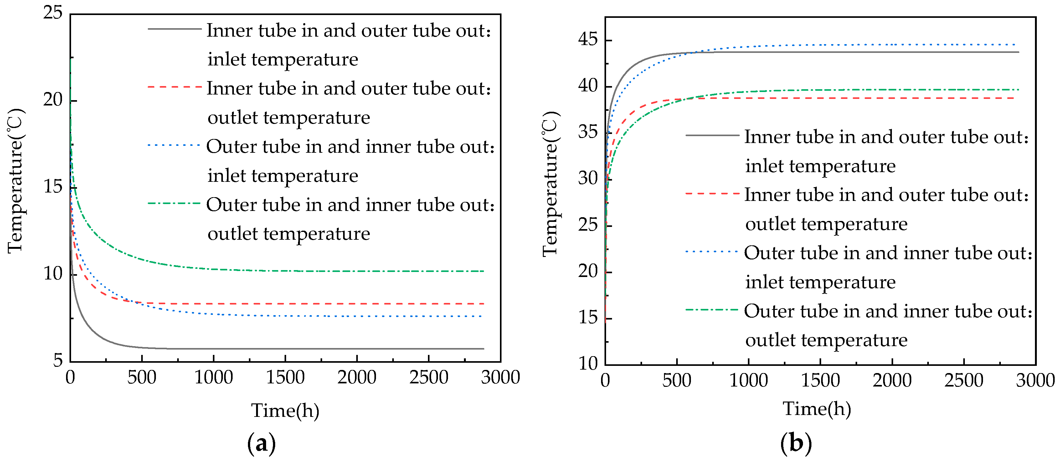
3.1. Selection of Circulation Mode

In the early stage of the multi-hole calculation, the appropriate circulation method must be first selected. The double-pipe heat exchanger pipeline includes an inner tube and an outer tube. For a single-hole heat exchanger, according to the different flow directions of the circulating liquid in the tube in the inner and outer tubes, the exchanger is divided into the “inner tube in and outer tube out” and the “outer tube in and inner tube out” configurations. Different flow directions of the circulating fluid are selected for simulation; the heat exchange in winter is set to 12 KW and the heat exchange in summer is set to 19 KW. The temperature changes of the inlet and outlet in winter and summer are analyzed, and the appropriate circulation mode is selected. The specific results are shown in Figure 3.
Figure 3 shows that with the continuous heat exchange between the circulating fluid and the surrounding rock and soil layers, the temperature of the surrounding rock and soil layers continuously changes. When the heat exchange is set to a certain value, the inlet and outlet temperatures will change at different magnitudes to achieve the corresponding heat exchange. For the outer tube in and the inner tube out of the heat exchanger, the circulating fluid enters the outer tube of the double-pipe and indirectly exchanges heat with the rock and soil layer through the backfill material and the borehole wall then flows out from the inner tube. The circulating fluid of the inner tube in and the outer tube out of the heat exchanger enters from the inner tube of the double-pipe and exchanges heat with the rock and soil layer through the inner tube wall, the outer tube circulating fluid, the borehole wall, and the backfill material.
Therefore, as seen in Figure 3a, during winter operation, the temperature at the inlet and outlet of the “inner tube in and outer tube out” heat exchanger is lower than that in the “outer tube in and inner tube out” configuration, to achieve the corresponding heat exchange. During summer operation (Figure 3b), the heat is dissipated underground. The temperature of the circulating liquid of the inner tube in and the outer tube out of the heat exchanger passes through the inner tube, and the heat is dissipated to the rock and soil layer. The circulating fluid in the outer tube also loses a certain amount of heat, while the “outer tube in and inner tube out” configuration mainly exchanges heat in the outer tube. In contrast, the temperature at the inlet and outlet of the “outer tube in and inner tube out” configuration is higher, but in summer, the difference between the inlet and outlet temperatures of the two modes of circulation is small.
In summary, when absorbing heat, the heat exchange of the “inner tube in and outer tube out” configuration has a larger thermal resistance, and the heat-exchange effect of the “outer tube in and inner tube out” configuration is better; when dissipating heat, the heat-exchange effect of the “inner tube in and outer tube out” configuration is slightly better, but the overall difference is small. Therefore, this simulation will take the outer tube in and the inner tube out of the heat exchanger as the research target for analysis.

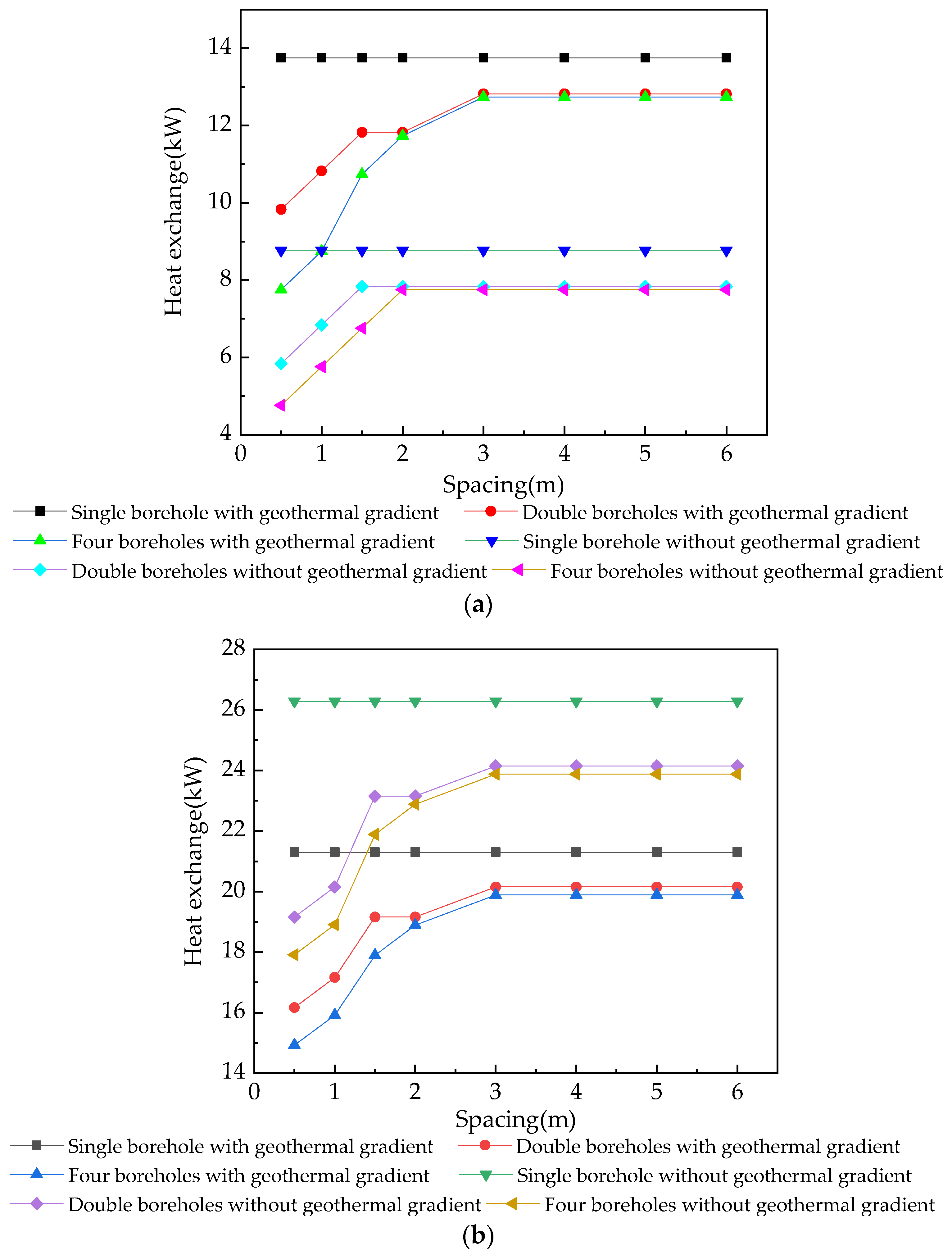
3.2. Changes in Heat Exchange

In winter, the nominal heat extraction calculation is generally used to define the maximum heat extraction. The virtual quantitative index determined by the simulation, that is, the heat extraction when the inlet temperature of the heat exchanger is not lower than 5 °C within 3 months of continuous operation, yields the nominal heat extraction [18]. Therefore, in summer, the heat exchange at which the inlet temperature should not be higher than 45 °C within 3 months of continuous operation is used as the maximum heat exchange; for the multi-hole heat exchanger, when the distance between the buried pipes changes, the heat exchange will also change. We take the drilling spacing as 0.5, 1, 1.5, 2, 3, 4, 5, and 6 m, respectively, with the system running for three months in winter and summer, comparing the heat exchange size, and selecting the most suitable spacing. The specific results are shown in Figure 4.
Figure 4 shows the amount of heat exchange at different distances within a certain period. The amount of heat exchange increases with an increasing drilling distance, but the increase is progressively smaller and finally tends to become stable; at the same time, the amount of heat exchange decreases with an increasing number of holes. When the number of holes increases, the interference between the holes also increases. When the distance between the holes is 0.5 m, whether in summer or winter, the heat exchange gap between single-, double-, and four-hole configurations is the largest, and the interference between the drilling holes is also the largest at this point. When the distance between the drilling holes is 3, 4, 5, and 6 m, the heat exchange is the largest and the change is slow; additionally, the influence between the drilling holes is small, but when the spacing is too large, the required ground area will also increase. Thus, when the drilling spacing is 3 m, the heat exchange effect is the best, is economically more reasonable, and is more in line with the actual engineering requirements. Therefore, in the following simulation, a heat exchanger with a borehole spacing of 3 m will be selected for the calculation, to analyze the changes in the other parameters.

3.3. Influence of the Geothermal Gradient on Heat Transfer

The geothermal gradient is the increase in the temperature of the rock and soil layer per unit depth, which refers to the growth rate of the temperature of the rock and soil layer with an increasing depth when the earth is not affected by the atmospheric temperature [19]. Therefore, the geothermal gradient is also an important indicator that affects the change in heat transfer. This simulation compares the amount of heat transfer when the geothermal gradient is dT/dZ = 0.03 °C/m and when there is no geothermal gradient. The specific results are shown in Figure 5.
Figure 5a shows that the heat transfer with a temperature gradient is higher than that without a temperature gradient during operation in winter. This is because the circulating fluid enters from the outer pipe, the temperature at the inlet is at its lowest, and the temperature of the surrounding rock and soil layer is also at its lowest. When there is a geothermal gradient, the temperature of the surrounding rock and soil layer continuously increases with increasing depth, and the temperature of the circulating fluid in the outer pipe also increases with increasing drilling depth. When there is no geothermal gradient, the temperature of the surrounding rock and soil layer changes little with increasing depth. When the temperature of the circulating fluid enters from the outer tube, it absorbs heat continuously as the depth increases. Since there is no temperature gradient in the rock and soil layers, the temperature of the circulating fluid increases and is constantly approaching the temperature of the rock and soil layers, while the temperature of the formation slightly changes. The amount of heat absorbed by the geotechnical layer is also reduced, which results in a smaller temperature difference between the inlet and outlet and a reduction in heat exchange.
When operating in summer, as shown in Figure 5b, heat exchange with a temperature gradient is lower than that without a temperature gradient. When the system is exothermic, the temperature of the circulating fluid is higher than the temperature of the rock and soil layer. When there is a temperature gradient, the temperature difference of the circulating fluid is large when it first enters the outer tube, and the heat dissipation is fast. However, as the drilling depth increases, the temperature of the rock and soil layer increases, which results in a decrease in the heat dissipation of the circulating fluid; the temperature difference between the inlet and the outlet decreases, and the heat exchange decreases. When there is no temperature gradient, the circulating fluid continuously exchanges heat with the rock and soil layers. The inlet temperature decreases continuously with increasing drilling depth, while the temperature of the surrounding rock and soil layer changes slightly; the circulating fluid continuously releases heat outward, and the heat exchange is relatively large. However, looking at the overall trend, the difference between the heat exchange with and without a temperature gradient in winter is slightly larger than the difference in heat exchange with or without a temperature gradient in summer, and the change trend of single-, double-, and four-hole configurations is the same. Therefore, the presence or absence of a temperature gradient will also affect the amount of heat exchange in the heat exchanger, and the presence of a temperature gradient is more conducive to heat exchange. Thus, the most suitable drilling distance is also verified to be 3 m.

3.4. Temperature Change

3.4.1. Changes in the Inlet and Outlet Temperatures

The heat exchange formula Q = mcΔt [20] shows that when the heat exchange is determined, the inlet and outlet temperatures are also determined. When the outside of the pipe continues to exchange heat, the temperature of the rock and soil layer changes. In order to achieve the corresponding external heat exchange, the temperature at the inlet and outlet of the circulating fluid is also constantly changing. In addition, the temperature at the inlet and outlet of the multi-borehole double-pipe heat exchanger is not merely affected by the temperature of the surrounding rock and soil layers; since the surrounding double-pipe also exchanges heat, the temperature of the geotechnical layer changes faster, so the inlet and outlet temperatures are also affected by the surrounding double-pipe. Therefore, the temperature of the inlet and outlet is also affected by the surrounding double-pipe, and the change in the inlet and outlet temperature also indirectly reflects the change in the surrounding soil temperature and the standard of heat exchange. In this simulation, the heat exchange in winter is 12 KW, and the heat exchange in summer is 19 KW. The specific results are given below.
Figure 6 shows that when the heat exchanger is continuously running to extract heat, it needs to continuously extract heat from the ground, which results in the loss of heat from the underground area and a continuous decrease in temperature. To obtain a certain amount of heat, the inlet and outlet temperatures will also continue to decrease. When the heat exchanger stops running, the temperature of the inlet and outlet slowly rises, to come close to the initial temperature of the surface; when dissipating heat, the circulating fluid continuously releases heat to the rock and soil layer, which causes the temperature of the rock and soil layer to rise. To release a certain amount of heat, the temperature of the inlet and outlet will continue to rise. After the operation is completed, the temperature slowly decreases close to the initial surface temperature, and then enters the next year’s cycle.
Figure 7 shows that when the heat exchanger operates in winter and when the heat exchange is constant, the temperature change at the inlet and outlet of the four holes is the largest, followed by the double holes; the single hole has the smallest temperature change. These results occur because the heat exchanger continuously takes heat from the rock and soil layers, which results in a continuous decrease in the temperature of the rock and soil layers. When the number of holes increases, the heat contained in the surrounding rock and soil layer is constant, and the multi-borehole heat exchanger is equally divided by this regional heat. The heat transfer of any one of the holes will be reduced compared to the heat obtained by the single-hole system; thus, the inlet and outlet temperatures of the multi-borehole heat exchanger must be lower than the inlet and outlet temperatures of the single-hole heat exchanger, to obtain the heat needed for the region. The greater the number of holes, the stronger the interference between the holes, and the lower the inlet and outlet temperatures.
Figure 8 shows that when the heat exchanger releases heat in summer, the heat exchange is constant, and the temperature at the inlet and outlet of the four-hole heat exchanger changes the most, followed by the double-hole heat exchanger; the single-hole configuration’s temperature change is the smallest. When the heat exchanger continuously releases heat into the soil, the temperature of the geotechnical layer continues to rise, and when the number of boreholes increases, the heat released to the geotechnical layer will increase so that the inlet and outlet temperatures will continue to rise to meet the corresponding heat transfer value. Moreover, if the number of boreholes increases further, the disturbance will be stronger, and the inlet and outlet temperatures of a single borehole will be higher.

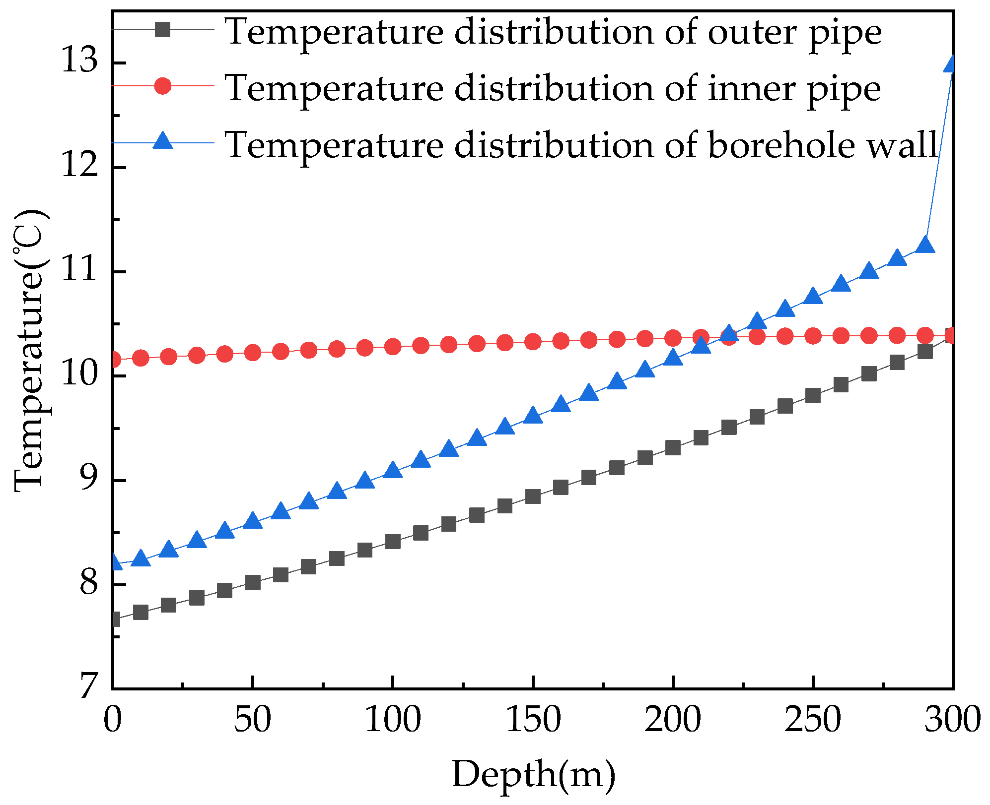
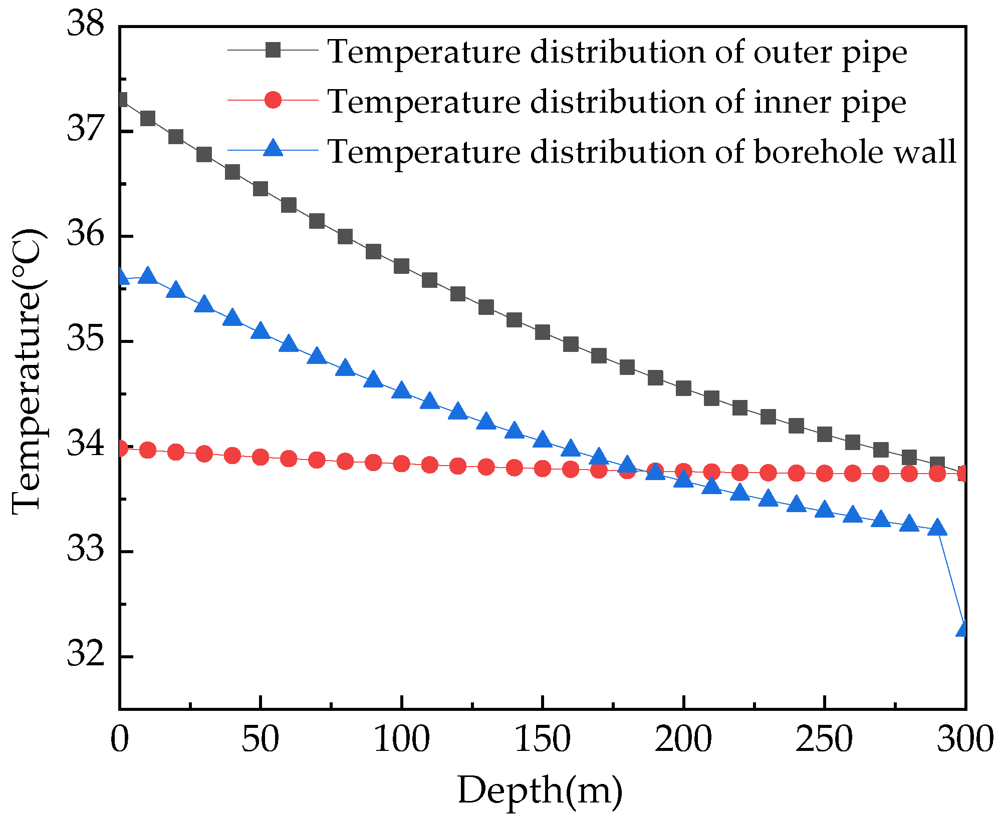
3.4.2. Temperature Distribution of the Borehole Wall and the Inner and Outer Pipe’s Circulating Liquid

The borehole wall is an intermediate substance that separates the circulating fluid from the rock and soil layer; it is affected by the temperature change of the external rock and soil layer and the temperature change of the circulating fluid in the pipe. The temperature change will affect the heat exchange of the entire circulating fluid system and indirectly reflect the change in the rock and soil temperature. Therefore, this simulation takes the double-hole heat exchanger as an example; the heat exchange in winter and summer is 12 KW and 19 KW, respectively. The temperature of the liquid is analyzed, and the temperature changes with increasing drilling depth; the heat transfer performance of different rock and soil layer depths is analyzed. The specific results are as follows.
Figure 9 shows that after the local buried-tube heat exchanger continuously runs for one winter, the temperature of the borehole wall and the temperature of the circulating fluid in the inner and outer tubes show varying degrees of an upwards trend with increasing drilling depth. During the operation of the heat exchanger, heat is continuously extracted from the underground rock and soil layer and the temperature of the inner and outer pipes continuously rises, which results in a decrease in the temperature of the geotechnical layer. After the exchanger’s operation is stopped, the temperature of the geotechnical layer slowly rises. Since the thermal conductivity of the inner pipe wall is small, the temperature changes less with the drilling depth. Additionally, the thermal conductivity of the outer tube borehole wall is larger with increasing depth; the temperature of the rock and soil layer increases and the temperature of the outer tube also increases. Finally, the temperature of the circulating fluid in the inner and outer tubes is mixed at the bottom of the borehole; the temperature of the circulating fluid in the inner and outer tubes is the same.
The borehole wall is an intermediate medium that connects the inside and outside of the borehole. The heat of the geotechnical layer first passes through the borehole wall and then enters the circulating fluid. Therefore, the temperature of the borehole wall is slightly higher than the temperature of the circulating fluid in the outer pipe and continues to rise as the borehole depth increases. At the bottom of the borehole, in addition to the heat from the surrounding geotechnical layers, the absorbed heat includes the heat of the geotechnical layer at the bottom of the borehole, so the temperature changes rapidly.
Figure 10 shows that after the local buried pipe runs in summer, the borehole wall temperature and the temperature of the circulating fluid in the inner and outer pipes show varying degrees of a decreasing trend with increasing borehole depth. The temperature of the rock and soil layer continues to rise, due to the heat release from the heat exchanger, and the temperature of the inner and outer tubes continues to decrease. After the operation is stopped, the temperature of the rock and soil layer gradually decreases. In winter, the temperature of the circulating fluid in the inner tube changes slightly, the outer tube exchanges heat with the rock and soil layer, and the temperature is higher than that of the surrounding rock and soil layer. Therefore, with the increase in drilling depth, the temperature continuously decreases and is mixed with the circulating fluid in the inner tube at the bottom of the drilling hole. The circulating fluid in the outer tube exchanges heat through the wall of the borehole. The heat first passes through the wall of the borehole and then enters the rock and soil layer. Therefore, the temperature of the borehole wall is lower than the temperature of the circulating fluid in the outer pipe, and the bottom of the borehole also receives heat exchanged from the bottom of the borehole, so that the temperature rapidly decreases.
In summary, the change in the temperature of the circulating fluid in the inner and outer tubes reflects the heat transfer performance of the inner and outer tubes, and the change in the borehole wall temperature also indirectly reflects the change in the temperature of the surrounding rock and soil layers at different depths. At the same time, the temperature change degree of the borehole wall also reflects the heat transfer capacity of the rock and soil layer at this depth. The faster the temperature of the borehole wall changes, the stronger the heat transfer effect of the rock and soil layer.

4. Comparative Analysis of the Experimental Data and Theoretical Calculation

To verify the accuracy of the heat transfer model in the early stages of the calculations, the experimental data were compared with the simulated data. Since the project was in the experimental test stage, a single-hole double-pipe heat exchanger was used, and two circulation methods were used: the “inner tube in and outer tube out” and the “outer tube in and inner tube out” configurations. Moreover, the experiments were carried out at different time periods. Therefore, when the simulation was carried out, the data are consistent with the experimental data parameter design, and the simulation calculation could be carried out.

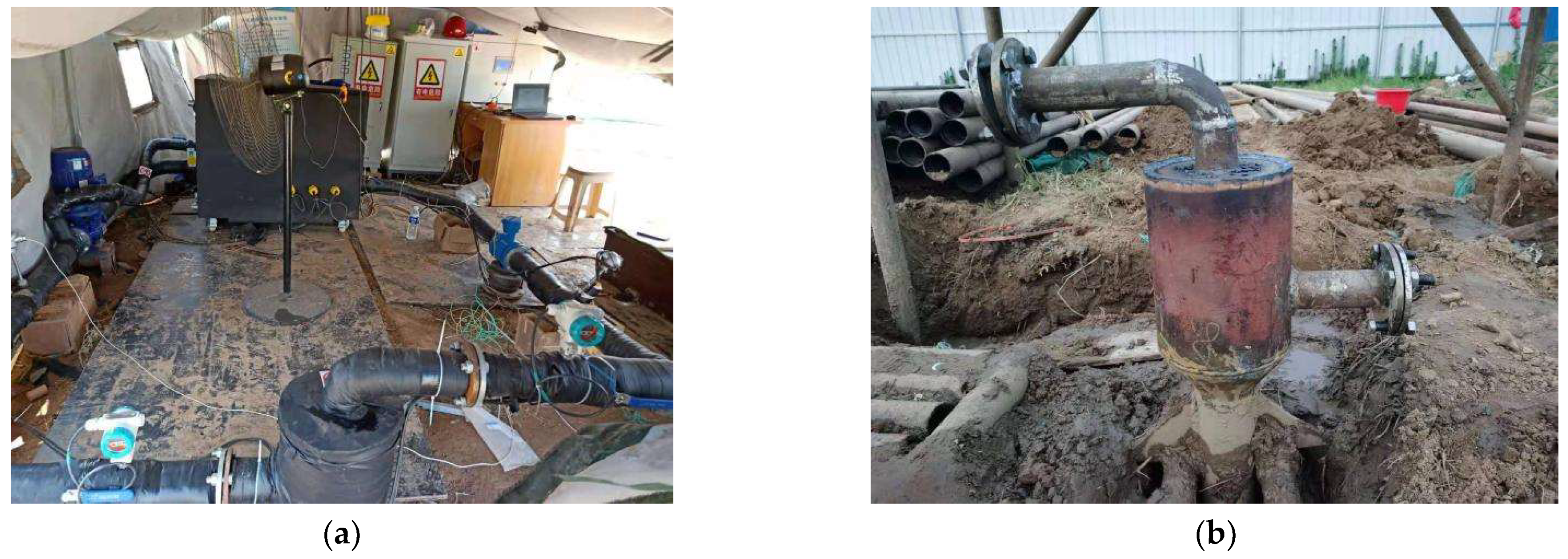
4.1. Experimental Test

Since the experimental test stage was in summer, only the heat dissipation test was carried out. The test equipment was connected up to the buried pipe heat exchanger to form a closed cycle system. By heating from the test end, the indoor heat absorption in summer was simulated, the changes in parameters such as the inlet and outlet water temperature, water flow, and heating power were continuously recorded; finally the geothermal physical parameters were calculated. The schematic diagram of the specific operation process (Figure 11) and the schematic diagram of the experimental equipment (Figure 12) are shown below.

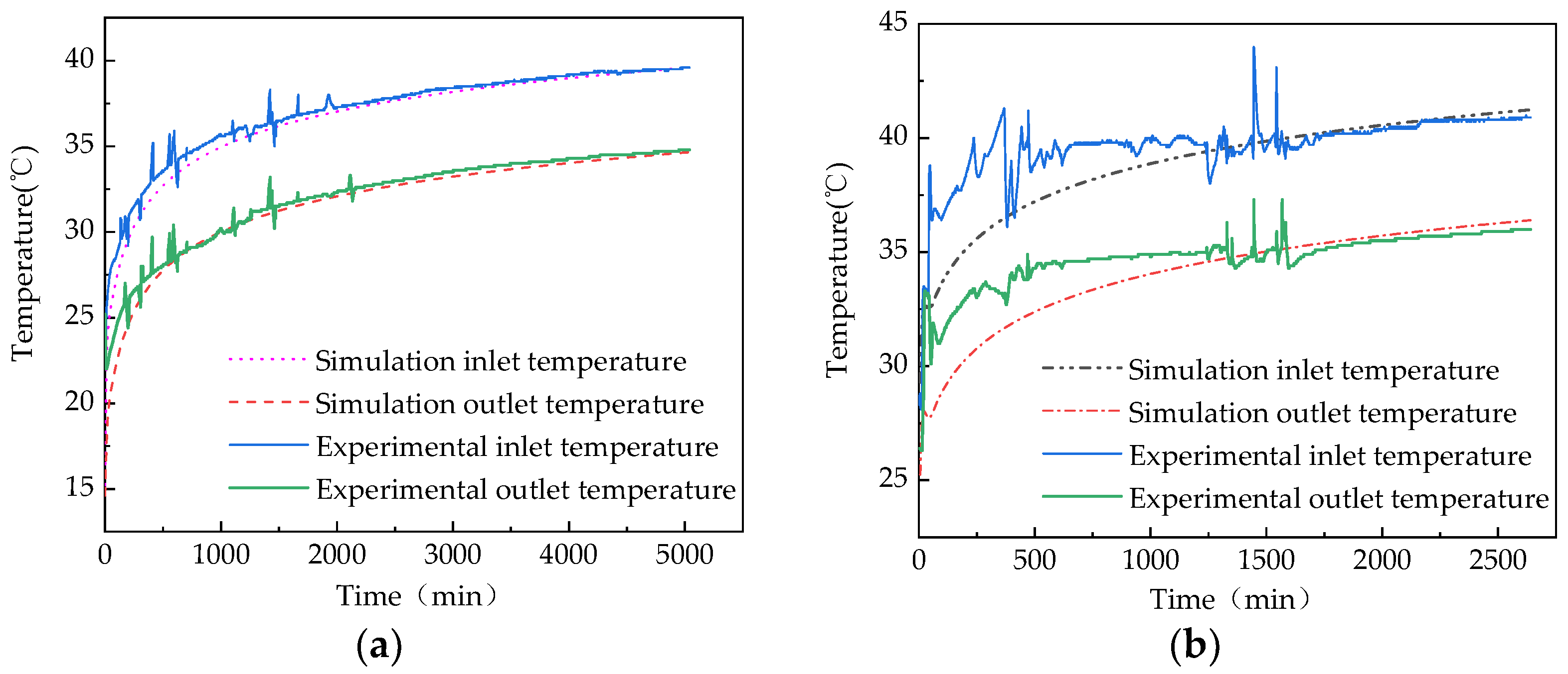
4.2. Comparison of the Inlet and Outlet Temperatures

The experimental test data were selected in two stages. The first stage monitored the inner tube in and the outer tube out of the heat exchanger. The operation time started at 3.30 p.m. on 25 June 2020 and ended at 3.30 a.m. on 29 June 2020. The test time was 84 h, and the circulating fluid flow rate was 3.5 m3/h. The second stage monitored the outer tube in and the inner tube out of the heat exchanger. The operation time started at 11 a.m. on 29 June 2020 and ended at 7 a.m. on 1 July 2020. The test time was 44 h, and the circulating fluid flow rate was 3.6 m3/h. At this time, the initial average temperature of the formation was 21.2 °C, and the inlet and outlet temperatures were obtained. Then, the results were compared with the data obtained from the simulation. The specific results are as follows.
Figure 13 shows that when the parameter settings are consistent, whether the settings are for the “outer tube in and inner tube out” configuration or the “inner tube in and outer tube out” configuration, there is a certain error between the experimental data and the simulated data. However, the overall trend is similar, and the experimental data fluctuate around the simulated data. In the early stage of the experiment, the data may be unstable and fluctuate due to the complex structure of the geotechnical layer and the influence of seepage. However, during the simulation, this instability is ignored because of its small effect, and the data are relatively stable. Furthermore, there is a gradually increasing trend, which is due to the large difference between the temperature of the circulating fluid and the temperature of the rock and soil layer in the initial stage, which results in a large increase in the data. However, this trend gradually becomes stable in the later stage. In addition, the comparison between the experimental data and the simulated data also proves the accuracy of the simulation calculations.

4.3. Comparison of the Heat Exchange

When conducting the experimental test, a certain value of heating power is first set to obtain the inlet and outlet temperature, water flow, etc., to establish the geothermal physical parameters, and to obtain the heat exchange value between the circulating fluid and the geotechnical layer in the experimental test stage. The parameter settings in the experimental stage are the same as those above, and the simulation parameters are consistent to compare the heat exchange between the experimental data and the outlet data. The specific results are as follows.
Figure 14 shows that the heat exchange corresponds to the inlet and outlet temperatures. Moreover, the experimental heat exchange fluctuates around the simulated heat exchange. The heating power is slightly lower than that of the simulated heat exchange, and the data are relatively stable. The change in the heat exchange is calculated by the change in the temperature and the fluctuation is large, which corresponds to the change in the inlet and outlet temperatures. The simulated data are cycled by the given initial value of the heat exchange to simulate the change in the inlet and outlet temperature and the heat exchange, and the data are relatively stable. For the “inner tube in and outer tube out” heat exchanger, the average value of the simulated heat exchange is 20.22 KW, and the average value of the experimental data is 20.4 KW. The average value of the simulated heat exchange rate of the “outer tube in and inner tube out” configuration is 20.45 KW, and the average value of the experimental data is 20.9 KW. In comparison, the gap is small; thus, the accuracy of the theoretical model is also verified.

5. Conclusions

Based on an air-conditioning cold and heat source project in a building in Handan City, this study conducts experimental tests, compares the obtained experimental data with the simulated data and, based on a single-hole system, compares the changes in the various parameters of double-hole and four-hole configurations during operation over a full year. The conclusions are as follows:
(1)
Comparing the inlet and outlet temperatures of the circulating liquid in different flow directions, when the heat exchanger continuously takes heat throughout the winter and continuously releases heat in the summer, the “outer tube in and inner tube out” circulation method is more conducive to the implementation of the project.
(2)
When comparing the heat exchange between single-hole, double-hole and four-hole configurations, whether in winter or summer, the heat exchange of the heat exchanger increases with increasing drilling distance and decreases as the number of drilled holes increases. Through comparison, the most suitable spacing is concluded to be 3 m when the project is implemented with a multiple-hole system.
(3)
A temperature gradient is more conducive to heat exchange. At the same time, the greater the number of boreholes, the stronger the interference between the boreholes, and the more obvious the temperature change at the inlet and outlet.
(4)
After the operation is completed in either winter or summer, the temperature of the borehole wall and the temperature of the inner and outer pipes will increase or decrease to varying degrees with the increase in the depth of the borehole; the more obvious the temperature changes of the circulating fluid in the inner and outer pipes, the more the pipe wall temperature is replaced and the better the thermal performance; finally, the change in the borehole wall temperature indirectly reflects the change in the temperature of the rock and soil layer with depth. The greater the temperature change of the borehole wall, the better the heat transfer performance of the rock and soil layer.
(5)
When comparing the simulated data with the experimental data, the error is small whether for the inlet and outlet temperature or the heat exchange, which verifies the applicability of the heat transfer model.

Author Contributions

W.L. simulated the parameters, organized the data, and completed the writing of the paper in combination with the corresponding charts. W.Z. selected the research content of the paper and revised and improved the content of the paper. Z.L. and H.Y. collect and organize the data. P.C. and F.Z. conduct the final verification of the paper. All authors have read and agreed to the published version of the manuscript.

Funding

The Plan of Guidance and Cultivation for Young Innovative Talents of Shandong Provincial Colleges and Universities. City School Integration Development Strategy Project (JNSX2021049). Leading Researcher Studio Fund of Jinan (No. 2019GXRC066).

Acknowledgments

The work described in this paper was supported by the Plan of Guidance and Cultivation for Young Innovative Talents of Shandong Provincial Colleges and Universities. This work was supported by the City School Integration Development Strategy Project (JNSX2021049). This work was supported by the Leading Researcher Studio Fund of Jinan (No. 2019GXRC066).

Conflicts of Interest

The authors declare no conflict of interest.

References

  1. Kong, Y.; Chen, C.; Shao, H.; Pang, Z.; Xiong, L.; Wang, J. Principle and capacity quantification of deep-borehole heat exchangers. Chin. J. Geophys. 2017, 60, 4741–4752. [Google Scholar]
  2. Luo, N.; Ren, X. Geothermal energy heating and cooling technology and application. Clean. World 2021, 37, 99–100. [Google Scholar]
  3. Hu, Y. The direct utilization of medium and shallow geothermal energy in China has ranked first in the world for many years. Pet. Refin. Eng. 2019, 49, 6. [Google Scholar]
  4. Guo, X.; Li, X. Study on current situation and development countermeasures of geothermal energy direct Utilization industry in China. Sol. Energy 2016, 17–20. [Google Scholar] [CrossRef]
  5. Shen, H. Present situation and development trend of geothermal energy exploitation and utilization in China. Sci. Technol. Innov. 2019, 20–21. [Google Scholar] [CrossRef]
  6. Renaud, T.; Verdin, P.; Falcone, G. Numerical simulation of a Deep Borehole Heat Exchanger in the Krafla geothermal system. Int. J. Heat Mass Transf. 2019, 143, 118496. [Google Scholar] [CrossRef]
  7. Li, J.; Xu, W.; Li, J.; Huang, S.; Li, Z.; Qiao, B.; Yang, C.; Sun, D.; Zhang, G. Heat extraction model and characteristics of coaxial deep borehole heat exchanger. Renew. Energy 2021, 169, 738. [Google Scholar] [CrossRef]
  8. Fang, L.; Diao, N.; Shao, Z.; Zhu, K.; Fang, Z. A computationally efficient numerical model for heat transfer simulation of deep borehole heat exchangers. Energy Build. 2018, 167, 79–88. [Google Scholar] [CrossRef]
  9. Cai, W.; Wang, F.; Chen, S.; Chen, C.; Liu, J.; Deng, J.; Kolditz, O.; Shao, H. Analysis of heat extraction performance and long-term sustainability for multiple deep borehole heat exchanger array: A project-based study. Appl. Energy 2021, 289, 116590. [Google Scholar] [CrossRef]
  10. Du, T.; Man, Y.; Jiang, G.; Li, S.; Zhang, X. Simulation Study on Optimal Drilling Spacing of Medium and Deep Buried Tube Heat Exchanger. Gas Heat 2019, 39, 21–24. [Google Scholar]
  11. Jia, L. Analytical Solution and Heat Transfer Analysis of Medium and Deep Buried Tube Heat Exchangers. Master’s Thesis, Shandong Jianzhu University, Jinan, China, 2021. [Google Scholar]
  12. Tang, X.; Cheng, L.; Xu, W.; Tingting, K.; Ying, D.; Jiasheng, T. Numerical study on factors that influence the heat transfer performance of mid-deep coaxial casing heat exchanger in the Xi’an area. Chin. J. Geol. 2021, 56, 985. [Google Scholar] [CrossRef]
  13. Zhang, F.; Fang, L.; Jia, L.; Man, Y.; Cui, P.; Zhang, W.; Fang, Z. A Dimension Reduction Algorithm for Numerical Simulation of Multi-Borehole Heat Exchangers. Renew. Energy 2021, 179, 2235–2245. [Google Scholar] [CrossRef]
  14. Jing, C. Study on geothermal geological characteristics and Exploitation and utilization in the eastern Plain of Handan. Master’s Thesis, China University of Geosciences, Wuhan, China, 2007. [Google Scholar]
  15. Dou, H.; Chen, X.; Xin, S.; Wang, H.; Zhou, Q. Experimental study on exploitation and irrigation of sandstone heat reservoir in Guantao Formation, Jizhong. Geotech. Investig. Surv. 2022, 50, 35–42. [Google Scholar]
  16. Zhang, Z.; Wu, X.; Zhao, J. Summary and suggestions of related standards and specificat- ons of ground source heat pumps and their systems. Sol. Energy 2015, 8–11+19. [Google Scholar] [CrossRef]
  17. Piechowski, M. Heat and mass transfer model of a ground heat exchanger: Validation and sensitivity analysis. Int. J. Energy Res. 1998, 22, 965. [Google Scholar] [CrossRef]
  18. Man, Y.; Jiang, G.; Du, T.; Fang, L.; Fang, Z. Modeling of deep and middle geothermal energy utilization in abandoned oil wells. Joural Shandong Jianzhu Univ. 2019, 34, 20. [Google Scholar] [CrossRef]
  19. Beier, R.A. Thermal response tests on deep borehole heat exchangers with geothermal gradient. Appl. Therm. Eng. 2020, 178, 115447. [Google Scholar] [CrossRef]
  20. Guan, C.; Zhao, S.; Zhang, W.; Sun, B.; Wang, J.; Sun, Z.; Fang, Z. Heat transfer analysis of ground heat exchangers for medium-deep geothermal energy heating. HV AC 2021, 51, 107–112. [Google Scholar]
Figure 1. Schematic diagram of the structure of the double-pipe heat exchanger.
Energies 15 04798 g001
Figure 2. Schematic diagram of the arrangement of porous heat exchangers. (a) Double boreholes. (b) Four boreholes.
Energies 15 04798 g002
Figure 3. Changes in the inlet and outlet temperatures under different circulation modes. (a) Changes in the inlet and outlet temperatures in winter. (b) Changes in the inlet and outlet temperatures in summer.
Energies 15 04798 g003
Figure 4. Changes in heat exchange. (a) Heat exchange in winter. (b) Heat exchange in summer.
Energies 15 04798 g004
Figure 5. Changes in heat exchange. (a) Heat exchange in winter. (b) Heat exchange in summer.
Energies 15 04798 g005
Figure 6. Changes in the inlet and outlet temperatures throughout the year.
Energies 15 04798 g006
Figure 7. Changes in the inlet and outlet temperatures in winter.
Energies 15 04798 g007
Figure 8. Changes in the inlet and outlet temperatures in summer.
Energies 15 04798 g008
Figure 9. Temperature distribution in winter.
Energies 15 04798 g009
Figure 10. Temperature distribution in summer.
Energies 15 04798 g010
Figure 11. Schematic diagram of the thermophysical properties test. (a) The “inner tube in and outer tube out” configuration. (b) The “outer tube in and inner tube out” configuration.
Energies 15 04798 g011
Figure 12. Test site. (a) A view of the entire test bench. (b) Sketch map of a double-pipe heat exchanger.
Energies 15 04798 g012
Figure 13. Comparison of the inlet and outlet temperatures under different circulation modes. (a) The “inner tube in and outer tube out” configuration. (b) The “outer tube in and inner tube out” configuration.
Energies 15 04798 g013
Figure 14. Comparison of the heat exchange under different circulation modes. (a) The “inner tube in and outer tube out” configuration. (b) The “outer tube in and inner tube out” configuration.
Energies 15 04798 g014
Table 1. Experimental parameters.
ParameterSymbolUnitNumerical Value
Drilling depthHm300
Geotechnical thermal conductivityλp3W/(m·K)2.09
Volumetric specific heat capacity of geotechnical layer(ρc)3J/(m3·K)2.46 × 106
Drilling diameterdbm0.133
Outer tube outer diameterd20m0.108
Outer tube inner diameterd2im0.099
Inner tube outer diameterd10m0.063
Inner tube inner diameterd1im0.0526
Thermal conductivity of inner tubeλp1W/(m·K)0.24
Thermal conductivity of outer tubeλp2W/(m·K)45
Thermal conductivity of backfill materialλgW/(m·K)1.83
Volume specific heat capacity of circulating liquidρcJ/(m3·K)4.187 × 106
Volume specific heat capacity of inner tube(ρc)1J/(m3·K)1.9 × 106
Volume specific heat capacity of outer tube(ρc)2J/(m3·K)3.45 × 106
Volume specific heat capacity of backfill material(ρc)gJ/(m3·K)2.42 × 106
Annual mean temperature of the atmosphere (surface temperature)Ta°C14.6
Surface convective heat transfer coefficientHaW/(m2·K)15
Heat flowqgW/m20.065
Publisher’s Note: MDPI stays neutral with regard to jurisdictional claims in published maps and institutional affiliations.

