Article

S-Transform Based Traveling Wave Directional Pilot Protection for Hybrid LCC-MMC-HVDC Transmission Line

School of Automation and Electronic Engineering, Qingdao University of Science & Technology, Qingdao 266061, China
*
Author to whom correspondence should be addressed.
Energies 2022, 15(13), 4802; https://doi.org/10.3390/en15134802
Submission received: 2 June 2022 / Revised: 25 June 2022 / Accepted: 27 June 2022 / Published: 30 June 2022
(This article belongs to the Special Issue HVDC Grids: Analysis, Protection and Applications)

Abstract

:
In this paper, the traveling wave protection issue of a hybrid high-voltage direct-current transmission line based on the line-commutated converter and modular multilevel converter is investigated. Generally, traveling wave protection based on voltage variation criterion, voltage variation rate criterion and current variation rate criterion is applied on hybrid high-voltage direct-current transmission lines as primary protection. There are two issues that should be addressed: (i) it has no fault direction identification capability which may cause wrong operation regarding external faults; and (ii) it does not consider the difference between line-commutated converter based rectifier station topology and modular multilevel converter based inverter station topology. Therefore, a novel traveling wave directional pilot protection principle for the hybrid high-voltage direct-current transmission line is proposed based on the S-transform. Firstly, the data processing capability of S-transform is described. Secondly, the typical traveling wave propagation process on a hybrid high-voltage direct-current transmission line is studied. Thirdly, a novel traveling wave fault direction identification principle is proposed. Eventually, based on PSCAD/EMTDC, a typical ±400 kV hybrid high-voltage direct-current transmission system is used for a case study to verify its robustness against fault location, fault resistance and fault type.

1. Introduction

Line-commutated converter (LCC) based high-voltage direct-current (HVDC) transmission systems have a number of advantages: large transmission capacity, low transmission loss and long transmission distance. However, the inverter converter has suffered from commutation failure issues for a long time [1,2,3,4]. Due to the working characteristics of IGBT and PWM control strategy, the modular multilevel converter (MMC) based HVDC converter has no commutation failure issue [5,6]. However, the construction cost of MMC-HVDC converters is much higher than that of LCC-HVDC converters. Therefore, to acquire the advantages of LCC-HVDC converters and MMC-HVDC converters, hybrid line-commutated converter and modular multilevel converter high-voltage direct-current (LCC-MMC-HVDC) technology is utilized in actual power systems. Generally, rectifier and inverter sides adopt LCC-HVDC and MMC-HVDC converters, respectively.
Currently, traveling wave (TW) protection is widely utilized on hybrid LCC-MMC-HVDC transmission lines and based on voltage variation, voltage variation rate and current variation rate criteria [7,8]. In fact, the utilized TW protection is based on transient quantity rather than true high frequency TW quantity. There are two issues: (1) no direction identification capability. Based on single-ended transient quantity, it has no ability to identify forward or backward directions correctly. (2) Threshold issue. Threshold values are highly related to TW protection’s reliability and sensitivity.
In order to overcome these issues, a number of scholars have proposed novel protection methods. Wang et al. [9] propose a TW directional pilot protection which is suitable for hybrid LCC-VSC-HVDC transmission lines. Similarly, Wang et al. [10] propose a novel hybrid directional comparison pilot protection scheme for the hybrid LCC-VSC-HVDC transmission line. Tang et al. [11] propose a novel hybrid LCC-MMC-HVDC topology which has DC transmission line fault clearance ability. Zheng et al. [12] propose a novel pilot protection method using the transient energy. Gijare et al. [13] pay attention to HVDC transmission line permanent faults in hybrid HVDC transmission systems. Wang et al. [14] studied hybrid HVDC transmission line boundary protection. Deng et al. [15] studied a single-ended TW protection principle according to full bandwidth TW in both time and frequency domains. Zou et al. [16] propose a novel directional pilot protection based on transient energy which is suitable for HVDC transmission lines. The above references have enough protection reliability, but the adaptability on hybrid LCC-MMC-HVDC transmission lines requires further research.
Aiming to solve these issues, this paper proposes a novel S-transform based TW directional pilot protection principle for hybrid LCC-MMC-HVDC transmission lines, which contributes in three different ways: (i) proposing a novel TW propagation characteristic analysis method of hybrid transmission systems; (ii) proposing a novel S-transform based TW directional pilot protection principle; (iii) using the whole bandwidth of the TW signal.
The rest of the paper is organized as follows. In Section 2, the principle of S-transform is introduced. In Section 3, the TW propagation process on LCC-MMC-HVDC transmission lines is studied. In Section 4, a novel S-transform based TW directional pilot protection principle is proposed. In Section 5, according to a ±400 kV hybrid LCC-MMC-HVDC simulation case based on PSCAD/EMTDC, the proposed TW protection principle’s robustness against fault type, fault resistance and fault location is proved. In Section 6, a concise summary is given.

2. S-Transform Principle

S-transform is a kind of time–frequency transformation principle which has advantages over CWT and SFT algorithms [17]. For a signal x ( t ) , the result of S-transform is illustrated by
W ( τ , d ) = + x ( t ) ω ( τ t , d ) d t
where d and τ denote the flexible parameter and the time-shift coefficient, respectively; ω ( τ t , d ) is a flexible time-shift function of the base wavelet. Since S-transform is a kind of CWT after phase angle correction, the transformation of x ( t ) can be described as the product of CWT itself and a phase angle modification parameter in the following:
S ( τ , f ) = e i 2 π f τ W ( τ , d )
where f and i respectively represent the time frequency and the imaginary unit. Taking Equation (1) into Equation (2), therefore,
S ( τ , f ) = + x ( t ) ω ( τ t , f ) e i 2 π f τ d t ω ( τ t , f ) = f 2 π e f 2 ( τ t ) 2 / 2
where ω ( τ t , f ) is a Gaussian window function. According to the above analysis, compared with the SFT algorithm, the Gaussian window’s height and width of the S-transform algorithm vary with frequency. Therefore, the disadvantage of a fixed Gaussian window of the SFT algorithm is overcome. Defining X ( f ) as the Fourier transformation result of original signal x ( t ) ,
S ( τ , f ) = + X ( υ + f ) e 2 π 2 υ 2 / f 2 + i 2 π τ υ d υ .
Then, the discrete S-transform is computed by
S j T , n N T = k = 0 N 1 X k + n N T e 2 π 2 k 2 / n 2 + i 2 π k j / N
where f n / N T ; τ j T ; T denotes sampling time step; j , k , n = 0 , 1 , · · · , N 1 .
The result of S-transform is an m × n order complex matrix S m × n . The phase angle and amplitude of x ( t ) can be described as:
S A n = angle ( S m × n ) S A m = abs ( S m × n )
where S A n and S A m represent phase angle matrix and amplitude matrix, respectively.

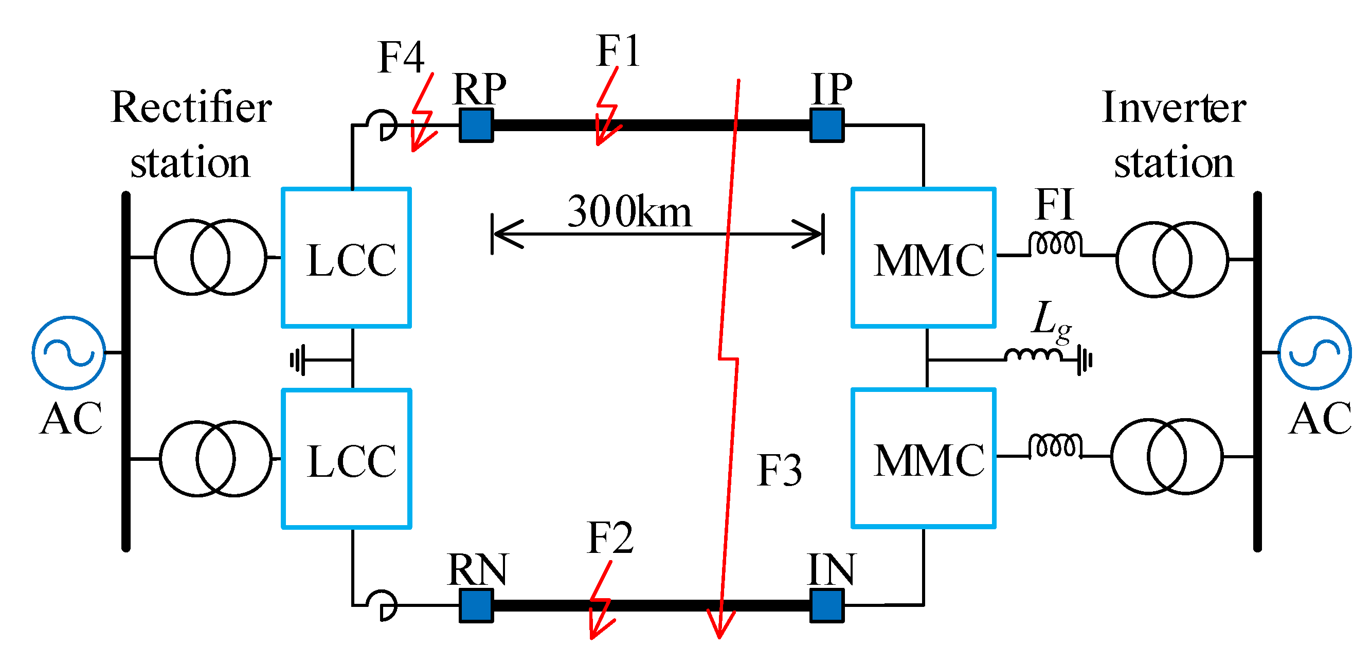
3. Typical Transmission System

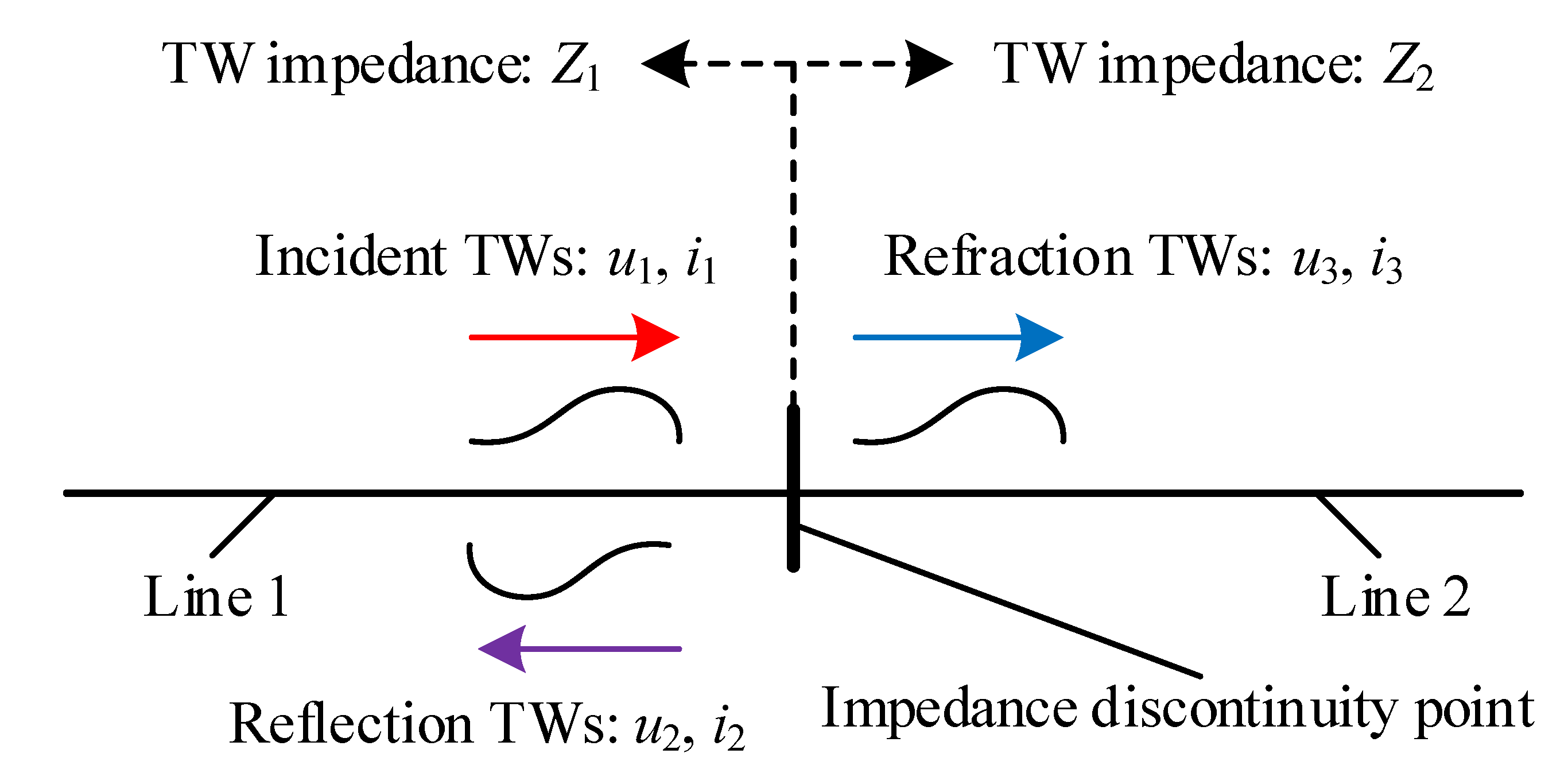
3.1. Reflection and Refraction of TW

Figure 1 presents the basic TW reflection and refraction phenomena [18]. As can be seen, the incident VTW ( u 1 ) and CTW ( i 1 ) propagate along line 1, and refraction and reflection happen at an impedance discontinuity point (generally busbar or fault point). In addition, the TW impedances at line 1 and line 2 are Z 1 and Z 2 , respectively. The reflection VTW and refraction VTW are u 2 and u 3 , respectively. The reflection CTW and refraction CTW are i 2 and i 3 , respectively. The forward direction of VTW is defined from transmission line to earth. The forward direction of CTW is its actual propagation direction. Hence, the reflection and refraction coefficients are obtained as
λ u = Z 2 Z 1 Z 2 + Z 1 λ i = Z 2 Z 1 Z 2 + Z 1 β u = 2 Z 2 Z 2 + Z 1 β i = 2 Z 1 Z 2 + Z 1
where λ u and β u are VTW reflection and refraction coefficients, respectively; λ i and β i are CTW reflection and refraction coefficients, respectively.

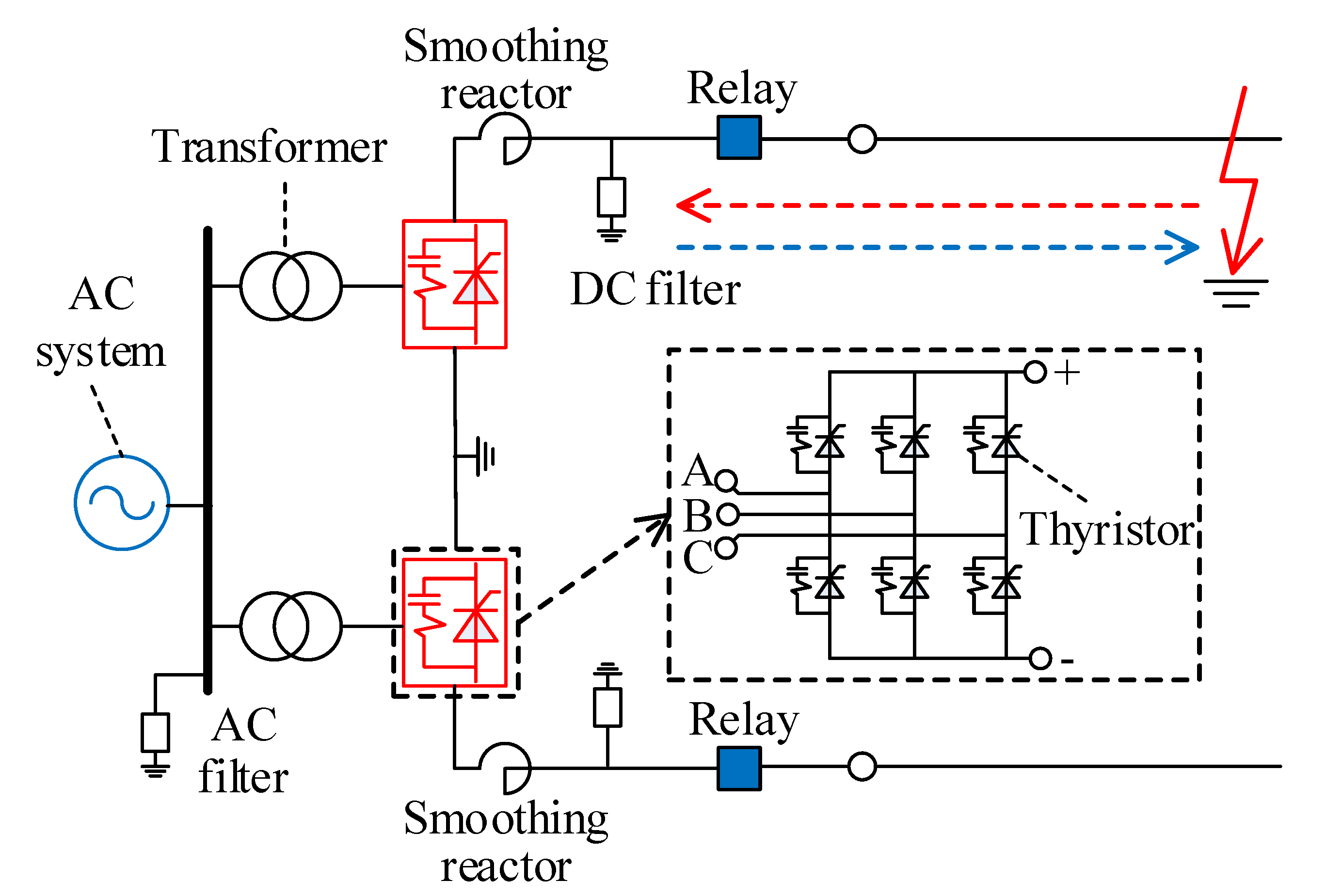
3.2. LCC-HVDC Rectifier Station

Generally, an LCC-HVDC station is applied at the rectifier side to obtain higher power transmission capacity, of which the typical topology is illustrated in Figure 2. The rectifier side includes a thyristor based converter, power transformer, relay, AC filter and DC filter. It generally adopts a constant DC current control strategy. Additionally, a large smoothing reactor is installed at the terminal of the transmission line. The wave impedances of the smoothing reactor and transmission line are described as Z S R and Z T L , respectively. Therefore, according to Equation (7), the reflection and refraction coefficients are
λ R u = Z S R Z T L Z S R + Z T L λ R i = Z S R Z T L Z S R + Z T L β R u = 2 Z S R Z S R + Z T L β R i = 2 Z T L Z S R + Z T L
where λ R u and λ R i are VTW and CTW reflection coefficients at the rectifier station, respectively; β R u and β R i are VTW and CTW refraction coefficients at the rectifier station, respectively.

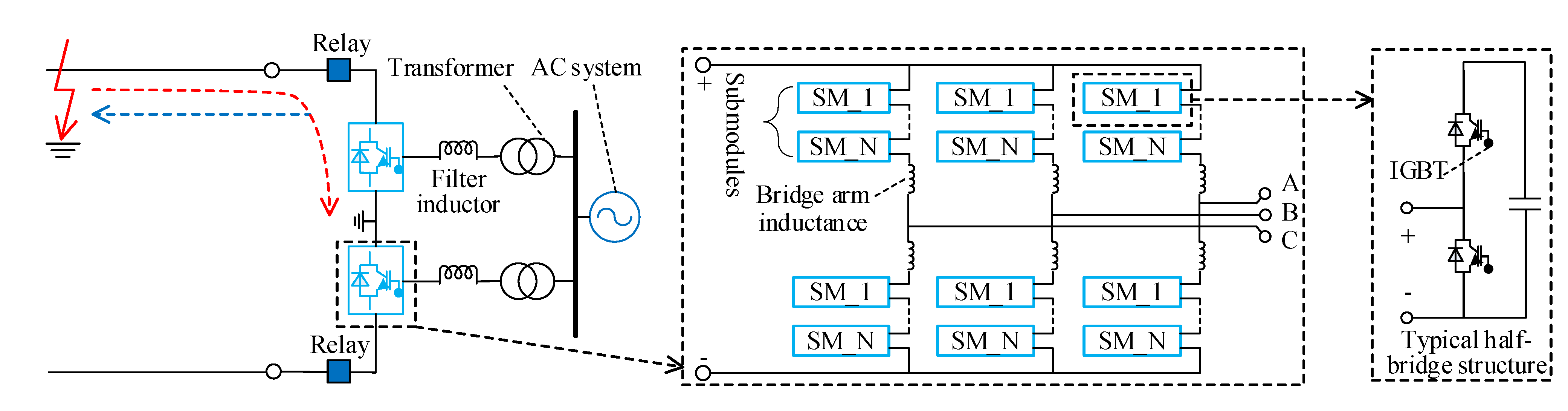
3.3. MMC-HVDC Inverter Station

An MMC-HVDC station is generally applied at the inverter side to avoid commutation failure. Figure 3 shows a typical structure of an MMC-HVDC inverter station, which comprises the IGBT based converter (including a number of SMs and bridge arm inductance), power transformer, relay and filter inductance. It generally adopts the constant DC voltage control and constant reactive power control strategies in the inverter side. After a fault occurs, the incident VTW signals arrive at the relay location. Afterwards, the refraction VTW signals pass through the converter into earth, and reflection VTW signals return to the fault location. Since the TW propagation process period is less than a few ms, the working state of the converters remains approximately unchanged. Therefore, the wave impedance of converters can be computed by
Z C O = j k 1 ω C j k 2 ω C + 2 j ω L = 4 π f L k 1 + k 2 2 π f C
where Z C O is wave impedance of the converter; ω and f respectively denote angular and time frequencies; k 1 and k 2 respectively represent the numbers of inserted SM capacitances of upper and lower bridge arms. Therefore, according to Equation (7), the reflection and refraction coefficients are
λ I u = Z C O Z T L Z C O + Z T L λ I i = Z C O Z T L Z C O + Z T L β I u = 2 Z C O Z C O + Z T L β I i = 2 Z T L Z C O + Z T L
where λ I u and λ I i are VTW and CTW reflection coefficients at thw inverter station, respectively; β I u and β I i are VTW and CTW refraction coefficients at the inverter station, respectively.

4. Protection Principle

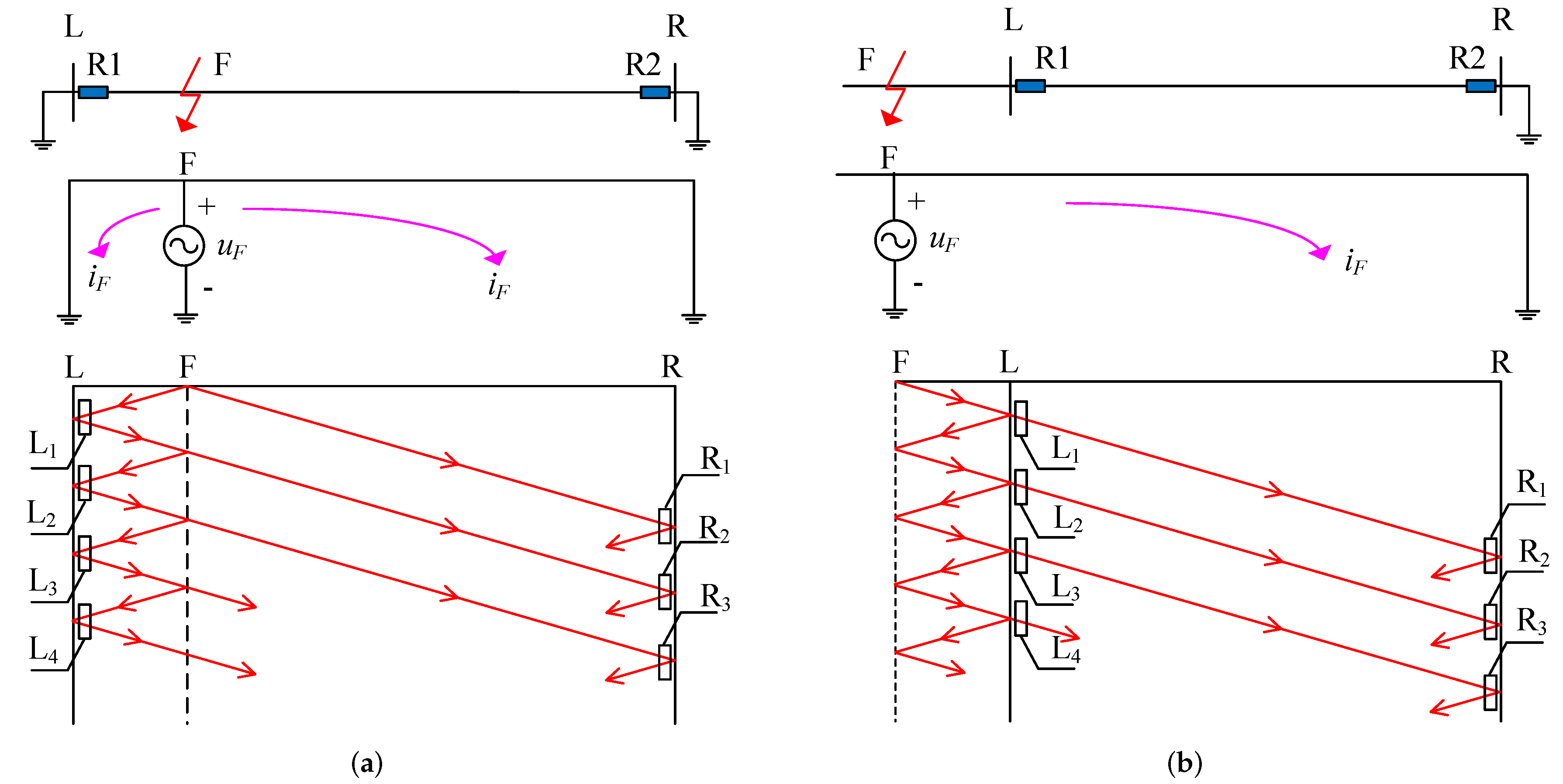
4.1. TW Propagation Characteristic in Hybrid LCC-MMC-HVDC Transmission System

Figure 4a,b provide the TW’s propagation characteristics with different faults. L and R stand for rectifier side and inverter side, respectively. L 1 , L 2 , L 3 and L 4 are TW mutations at the rectifier side. R 1 , R 2 and R 3 are TW mutations at the inverter side.
Table 1 and Table 2 describe both terminals’ TW mutations under different fault types. u ( t ) and i ( t ) represent VTW and CTW signals, respectively. λ L u and λ L i represent the rectifier side’s VTW reflection coefficient and CTW reflection coefficient, respectively. λ F u and λ F i represent the fault location’s VTW reflection coefficient and CTW reflection coefficient, respectively. λ R u and λ R i represent the inverter side’s VTW reflection coefficient and CTW reflection coefficient, respectively. β F u and β F i represent the fault location’s VTW refraction coefficient and CTW refraction coefficient, respectively. β L u and β L i represent the rectifier side’s VTW refraction coefficient and CTW refraction coefficient, respectively. u F and i F represent the initial VTW and CTW, respectively. L 1 , L 2 and L 3 represent the different TW mutations at the rectifier side. R 1 , R 2 and R 3 represent the different TW mutations at the inverter side. α L and α R represent the angle phase differences of VTW and CTW of the rectifier side and inverter side, respectively. Generally, 1 < λ L u = λ L i < 1 , 1 < λ R u = λ R i < 1 , 1 < λ F u = λ F i < 1 , β L u , β L i , β F u , β F i > 0 . In addition, the initial VTW ( u F ) and initial CTW ( i F ) have the same polarities.

4.2. Fault Direction Identification Algorithm

Define the fault direction identification coefficient,
E = j = 0 N 1 k = 10 M P j T , k f s P j T , k f s = A m j T , k f s × A n j T , k f s A m = abs S u j T , k f s × abs S i j T , k f s A n = angle S u j T , k f s angle S i j T , k f s ,
where E represents the fault direction identification coefficient; j T , N and T represent sampling time, data window length and time sampling step ( j = 0 , 1 , · · · , N 1 ; N = 1000 ; T = 1 μ s in this paper), respectively; k f s , M and f s represent sampling frequency, maximum frequency and frequency sampling step ( k = 10 , 11 , · · · , M ; M = 500 ; f s = 1 kHz in this paper), respectively; P, A m and A n stand for instantaneous power, instantaneous amplitude and instantaneous phase angle, respectively; S u and S i represent S-transform matrixes of VTW and CTW, respectively. According to Table 1 and Table 2, based on Equation (11):
  • If it is a forward fault for the relay, the phase angle difference between VTW and CTW is approximately equal to π . In other words, the A n j T , k f s = π . Therefore,
    E = j = 0 N 1 k = 10 M P j T , k f s = π × j = 0 N 1 k = 10 M A m j T , k f s 0 .
  • If it is a backward fault for the relay, the phase angle difference between VTW and CTW is approximately equal to 0. In other words, the A n j T , k f s = 0 . Therefore,
    E = j = 0 N 1 k = 10 M P j T , k f s = 0 × j = 0 N 1 k = 10 M A m j T , k f s 0 .
Based on Equations (12) and (13), the fault direction identification algorithm is expressed by:
E Δ forward fault E < Δ backward fault
where Δ is the experience threshold value ( Δ = 50 MVA·rad).

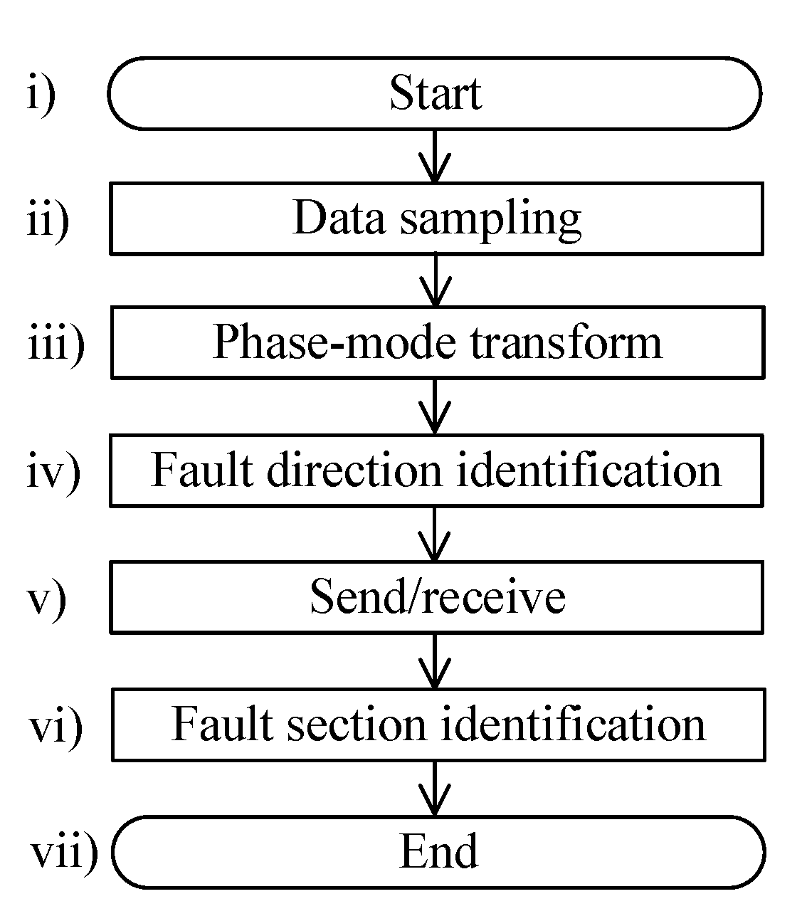
4.3. TW Protection Implementation

Figure 5 describes protection implementation, and it can be separated into several steps:
(i)
Start.
(ii)
Data sampling. The VTW and CTW data are sampled by a 1 MHz sampling rate, and the data window in this paper is 1 ms.
(iii)
Phase-mode transform. In order to adapt to different fault types, the paper adopts a positive sequence to calculate
M 1 M 0 = 1 1 1 1 P + P ,
where M 1 and M 0 represent positive and zero sequence signals, respectively; P + and P are positive and negative pole signals, respectively.
(iv)
Fault direction identification. Based on Section 4.2, the fault direction identification coefficient can be obtained. Afterwards, the fault direction is identified.
(v)
Send/receive. Two terminals exchange fault direction identification results, generally through an optical cable.
(vi)
Fault section identification. If the fault direction identification results of two terminals are both forward faults, the internal fault can be determined. Otherwise, an external fault can be determined.
(vii)
End.

5. Case Studies

5.1. Simulation Model

According to Figure 6, a typical ±400 kV hybrid LCC-MMC-HVDC simulation case is established via the simulation software PSCAD/EMTDC [19,20]. For the study case, the converter topology of the LCC rectifier side and MMC inverter side are respectively illustrated in Figure 2 and Figure 3. The rectifier side adopts the constant DC current control strategy. The inverter side adopts the constant DC voltage and constant reactive power control strategies. The HVDC transmission line adopts a frequency dependent model. Meanwhile, the simulation rate is set to 1 MHz. F1, F2 and F3 represent the PG, NG and PN internal fault cases, respectively. F4 represents the PG external fault. In the simulation, the faulty signals are acquired at transmission line terminals (RP, RN, IP and IN), and afterwards the protection algorithms can proceed and respond to the fault. All the simulation parameters are refer to an actual power grid.

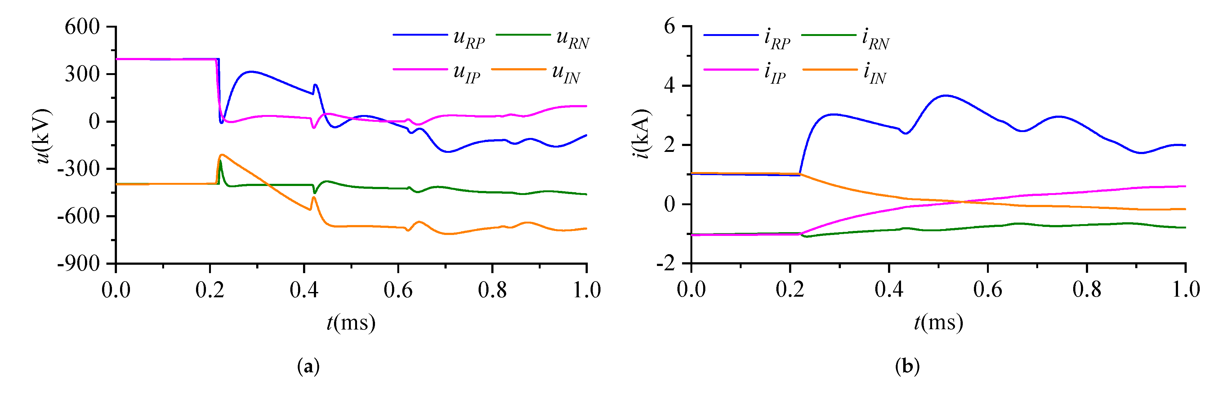
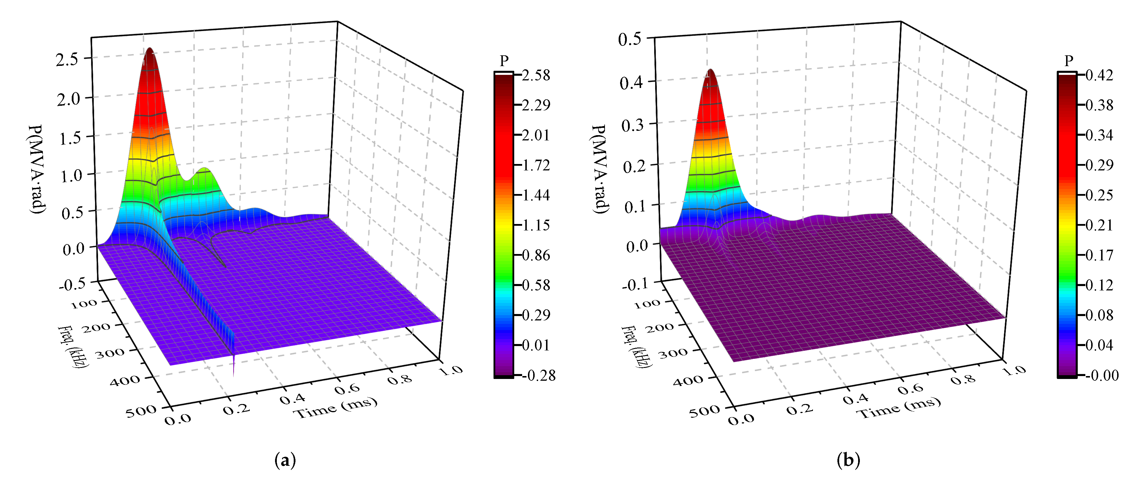
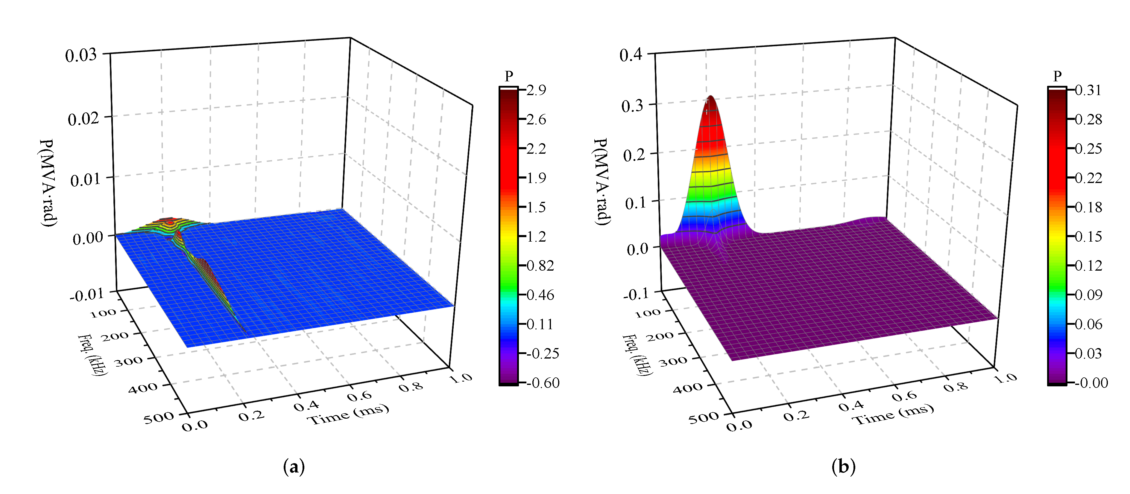
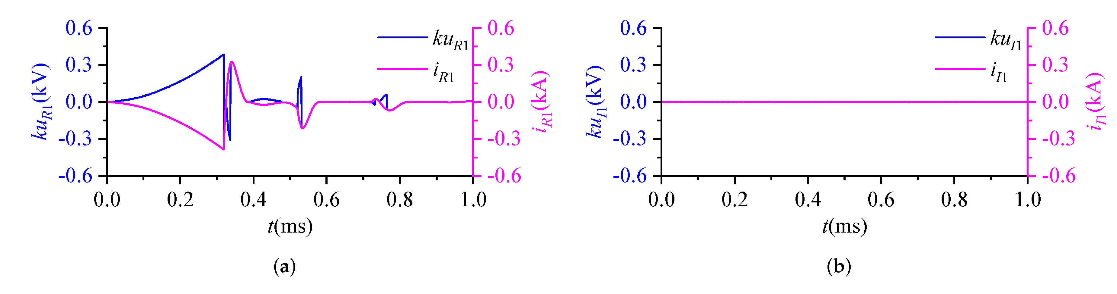
5.2. Typical Fault Simulation

Figure 7 shows the VTWs and CTWs of both terminals with a typical internal fault (F1). The fault occurs at F1 (30 km away from the LCC rectifier side, PG fault, 0 fault resistance). u R P and u R N are respectively the VTWs of positive and negative transmission lines of the rectifier station. u I P and u I N are respectively the VTWs of positive and negative transmission lines of the inverter station. i R P and i R N are respectively the CTWs of positive and negative transmission lines of the rectifier station. i I P and i I N are respectively the CTWs of positive and negative transmission lines of the inverter station. According to Figure 7, Figure 8 shows the positive sequence mode VTWs and CTWs of both terminals with an internal fault (F1). u R 1 and i R 1 are the positive sequence mode VTW and CTW of the rectifier side, respectively. u I 1 and i I 1 are the positive sequence mode VTW and CTW of the inverter side, respectively. In order to compare the proposed protection principle with the state-of-the-art work, comparison simulation results are illustrated.

5.2.1. The Proposed Protection Principle

Based on Figure 8, Figure 9 shows the instantaneous power of both terminals with an internal fault. As can be seen, the instantaneous power varies with different sampling times and frequencies. Accordingly, based on Equation (11), the fault direction identification coefficients of both terminals are 8004.4 MVA · rad and 600.3 MVA · rad , respectively. Based on Equation (14) and Section 4.3, the internal fault is determined correctly. Similarly, a typical external fault is simulated. The fault happens at F2 (near the LCC-HVDC rectifier station, PG fault, 50 Ω grounding resistance). The instantaneous power is described in Figure 10. Accordingly, based on Equation (11), the fault direction identification coefficients of both terminals are 9.8 MVA · rad and 365.0 MVA · rad , respectively. Based on Equation (14) and Section 4.3, the external fault is determined correctly.

5.2.2. The State-of-the-Art Work

We choose [21] as a comparable work, of which the fault direction discrimination parameter can be described as
γ = j = 0 N 1 k u ( k ) i ( k ) j = 0 N 1 i 2 ( k )
where k is the sampling point; u ( t ) and i ( t ) are respectively the intrinsic mode functions of VTW and CTW which are obtained by an empirical mode decomposition algorithm; k is the VTW amplitude conditioning factor.
Based on Figure 8, Figure 11 illustrates the comparison chart of k u and i of both terminals with an internal fault (F1). Based on [21], the fault location discrimination parameters of both terminals are −0.586 and 0.0089, respectively. As can be seen, for the relay away from the fault location, the protection principle cannot act correctly.

5.3. Simulations under the Influence of Fault Location Issue

To validate the performances of the proposed TW protection method under the influence of a fault location issue, a number of cases are simulated, of which the results are provided in Figure 12 where Figure 12a–c represent the PG, NG and PN faults, respectively. Additionally, E R 1 and E I 1 are fault direction identification coefficients. As shown, under the influence of a fault type issue (PG fault, NG fault and PN fault) and fault location issue (0–300 km away from the converters), the proposed protection can identify fault direction correctly, implying a good reliability.

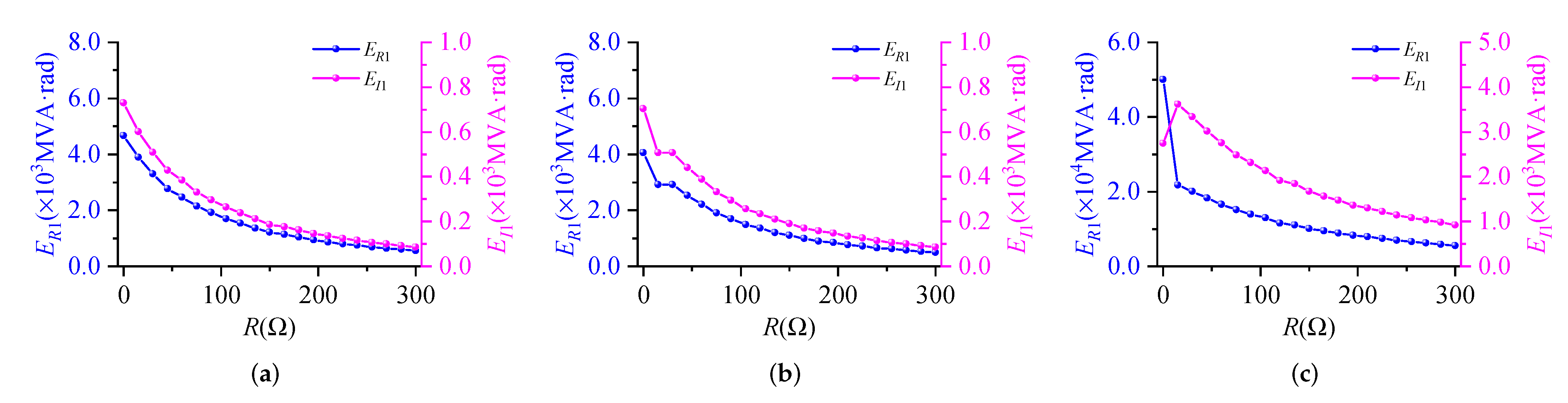
5.4. Simulations under the Influence of Fault Resistance Issue

To validate the performances of the proposed TW protection method under the influence of a fault resistance issue, a number of cases are simulated, of which the results are provided in Figure 13 where Figure 13a–c represent the PG, NG and PN faults, respectively. In addition, E R 1 and E I 1 are fault direction identification coefficients. As shown, under the influence of a fault type issue (PG fault, NG fault and PN fault) and fault resistance issue (0 to 300 Ω ), the proposed protection can identify fault direction correctly, implying a good reliability.

6. Conclusions

Based on S-transform, this paper proposes a novel TW directional pilot protection algorithm for a hybrid LCC-MMC-HVDC transmission line including a fault direction identification algorithm and complete implementation method. Compared with the existing literature, the performances of the proposed method have three contributions:
(i)
The novel protection algorithm has good adaptability to a hybrid LCC-MMC-HVDC transmission line.
(ii)
The novel protection algorithm has the ability to identify fault section information (internal and external faults) correctly. Additionally, it is not affected by factors such as fault location, fault resistance and fault type.
(iii)
Light data exchange burden and no time synchronization pressure. Only fault direction identification coefficients are required to be transmitted via a communication channel (e.g., optical cable). In addition, no time synchronization system is required.
However, to obtain high protection reliability, it requires a data transmission channel such as an optical cable. Additionally, the adaptability of the proposed method in a hybrid HVDC system with a full bridge MMC-HVDC converter or multiterminal power grids still needs further research.

Author Contributions

Conceptualization, W.Z. and D.W.; methodology, W.Z.; software, W.Z.; validation, W.Z.; formal analysis, W.Z.; investigation, W.Z.; resources, D.W.; data curation, W.Z.; writing—original draft preparation, W.Z.; writing—review and editing, D.W.; visualization, W.Z.; supervision, D.W.; project administration, W.Z.; funding acquisition, D.W.; All authors have read and agreed to the published version of the manuscript.

Funding

This research was funded by the Natural Science Foundation of Shandong Province under Grant ZR2020QE213.

Conflicts of Interest

The authors declare no conflict of interest.

Abbreviations

The following abbreviations are used in this manuscript:
LCCLine commutated converter
MMCModular multilevel converter
VSCVoltage source converter
HVDCHigh-voltage direct current
TWTraveling wave
IGBTInsulated gate bipolar transistor
PWMPulse width modulation
VTWVoltage traveling wave
CTWCurrent traveling wave
PGPositive pole to ground
NGNegative pole to ground
PNPositive pole to negative pole
CWTContinuous wavelet transform
SFTShort-time Fourier transform
SMSubmodule

References

  1. Luo, S.B.; Gao, H.L.; Wang, D.; Zou, G.B. Non-unit transient based boundary protection for UHV transmission lines. Int. J. Electr. Power Energy Syst. 2018, 102, 349–363. [Google Scholar] [CrossRef]
  2. Zheng, J.C.; Wen, M.H.; Chen, Y.; Shao, X.N. A novel differential protection scheme for HVDC transmission lines. Int. J. Electr. Power Energy Syst. 2018, 94, 171–178. [Google Scholar] [CrossRef]
  3. Chen, G.; Hao, M.; Xu, Z.; Vaughan, A.; Cao, J.; Wang, H. Review of high voltage direct current cables. CSEE J. Power Energy Syst. 2015, 1, 9–21. [Google Scholar] [CrossRef]
  4. Zhang, Y.; Tai, N.; Xu, B. Fault analysis and traveling-wave protection scheme for bipolar HVDC lines. IEEE Trans. Power Deliv. 2012, 27, 1583–1591. [Google Scholar] [CrossRef]
  5. Huang, Q.; Zou, G.B.; Wei, X.Y.; Sun, C.J.; Gao, H.L. A non unit line protection scheme for MMC-based multi-terminal HVDC grid. Int. J. Electr. Power Energy Syst. 2019, 107, 1–9. [Google Scholar] [CrossRef]
  6. Xiao, H.Q.; Xu, Z.; Wang, S.J.; Liu, S.; Jiang, W. Control strategy for multi-infeed MMC-based HVDC system connected to weak grid. In Proceedings of the 2017 IEEE Power Energy Society General Meeting, Chicago, IL, USA, 16–20 July 2017; pp. 1–5. [Google Scholar]
  7. Jin, X.F.; Song, G.B.; Ma, Z.B. A novel pilot protection for VSC-HVDC transmission lines based on parameter identification. In Proceedings of the 12th IET International Conference on Developments in Power System Protection (DPSP 2014), Copenhagen, Denmark, 31 March–3 April 2014; pp. 1–6. [Google Scholar]
  8. An, W.; Wei, C.Z.; Mou, M.; Huang, W.F.; Jin, X.; Ye, H. Simulation and analysis of the control and protection performance for a multi terminal VSC-HVDC system. In Proceedings of the 13th International Conference on Development in Power System Protection 2016 (DPSP), Edinburgh, UK, 7–10 March 2016; pp. 1–4. [Google Scholar]
  9. Wang, D.; Hou, M.Q.; Gao, M.Y.; Qiao, F. Travelling wave directional pilot protection for hybrid HVDC transmission line. Int. J. Electr. Power Energy Syst. 2019, 107, 615–627. [Google Scholar] [CrossRef]
  10. Wang, Y.; Zhang, B.H. A novel hybrid directional comparison pilot protection scheme for the LCC-VSC hybrid hvdc transmission lines. In Proceedings of the 13th International Conference on Development in Power System Protection 2016 (DPSP), Edinburgh, UK, 7–10 March 2016; pp. 1–6. [Google Scholar]
  11. Tang, G.; Xu, Z. A LCC and MMC hybrid HVDC topology with DC line fault clearance capability. Int. J. Electr. Power Energy Syst. 2014, 62, 419–428. [Google Scholar] [CrossRef]
  12. Zheng, X.D.; Tai, N.L.; Yang, G.L.; Ding, H.Y. A transient protection scheme for HVDC transmission line. IEEE Trans. Power Deliv. 2012, 27, 718–724. [Google Scholar] [CrossRef]
  13. Gijare, P.P.; Tade, S.V. Protection of permanent faults on DC overhead lines in hybrid converter based HVDC system. In Proceedings of the 2015 International Conference on Energy Systems and Applications, Pune, India, 30 October–1 November 2015; pp. 302–305. [Google Scholar]
  14. Wang, Y.T.; Zhang, B.H. Study on the transmission line boundary characteristics of the hybrid HVDC system. In Proceedings of the 2016 IEEE PES Asia Pacific Power and Energy Engineering Conference (APPEEC), Xi’an, China, 25–28 October 2016; pp. 1311–1315. [Google Scholar]
  15. Deng, F.; Li, X.R.; Zeng, X.J. Single-ended travelling wave protection algorithm based on full waveform in the time and frequency domains. IET Gener. Transm. Distrib. 2018, 12, 3680–3691. [Google Scholar] [CrossRef]
  16. Zou, G.B.; Huang, Q.; Song, S.L.; Tong, B.B.; Gao, H.L. Novel transient-energy-based directional pilot protection method for HVDC line. Prot. Control. Mod. Power Syst. 2017, 2, 159–168. [Google Scholar] [CrossRef]
  17. Li, Z.; Zou, G.B.; Du, T.; Yang, W.J. S-transform based pilot protection method for hvdc transmission lines. In Proceedings of the 2015 5th International Conference on Electric Utility Deregulation and Restructuring and Power Technologies (DRPT), Changsha, China, 26–29 November 2015; pp. 1667–1672. [Google Scholar]
  18. Wang, D.; Gao, H.L.; Luo, S.B.; Zou, G.B. Travelling wave pilot protection for LCC-HVDC transmission lines based on electronic transformers’ differential output characteristic. Int. J. Ofelectrical Power Energy Syst. 2017, 93, 283–290. [Google Scholar] [CrossRef]
  19. Krishna, T.N.V.; Sathishkumar, P.; Himasree, P.; Punnoose, D.; Raghavendra, K.V.G.; Himanshu; Naresh, B.; Rana, R.A.; Kim, H.J. 4T Analog MOS Control-High Voltage High Frequency (HVHF) Plasma Switching Power Supply for Water Purification in Industrial Applications. Electronics 2018, 7, 245. [Google Scholar] [CrossRef] [Green Version]
  20. Krishna, T.N.V.; Himasree, P.; Rao, S.S.; Kumar, Y.A.; Kundakarla, N.B.; Kim, H.J. Design and Devel-opment of a Digital Controlled Dielectric Barrier Discharge (DBD) AC Power Supply for Ozone Generation. J. Sci. Ind. Res. 2020, 79, 1057–1068. [Google Scholar]
  21. Wang, D.; Gao, H.L.; Luo, S.B.; Zou, G.B. Ultra-high-speed travelling wave protection of transmission line using polarity comparison principle based on empirical mode decomposition. Math. Probl. Eng. 2015, 2015, 1–9. [Google Scholar] [CrossRef]
Figure 1. TW reflection and refraction.
Energies 15 04802 g001
Figure 2. Typical structure of LCC-HVDC rectifier station.
Energies 15 04802 g002
Figure 3. Typical structure of MMC-HVDC inverter station.
Energies 15 04802 g003
Figure 4. TW propagation process. (a) Internal fault. (b) External fault.
Energies 15 04802 g004
Figure 5. TW protection implementation.
Energies 15 04802 g005
Figure 6. PSCAD simulation case.
Energies 15 04802 g006
Figure 7. VTWs and CTWs of both terminals with internal fault (F1). (a) VTWs of both terminals. (b) CTWs of both terminals.
Energies 15 04802 g007
Figure 8. Positive sequence mode VTWs and CTWs of both terminals with internal fault (F1). (a) Positive sequence mode VTW and CTW of rectifier side. (b) Positive sequence mode VTW and CTW of inverter side.
Energies 15 04802 g008
Figure 9. Instantaneous power of both terminals with internal fault (F1). (a) Instantaneous power of rectifier side. (b) Instantaneous power of inverter side.
Energies 15 04802 g009
Figure 10. Instantaneous power of both terminals with external fault (F4). (a) Instantaneous power of rectifier side. (b) Instantaneous power of inverter side.
Energies 15 04802 g010
Figure 11. Comparison chart of k u and i of both terminals with internal fault (F1). (a) Rectifier side. (b) Inverter side.
Energies 15 04802 g011
Figure 12. Fault direction identification coefficients with different fault locations. (a) PG fault. (b) NG fault. (c) PN fault.
Energies 15 04802 g012
Figure 13. Fault direction identification coefficients with different fault resistances. (a) PG fault. (b) NG fault. (c) PN fault.
Energies 15 04802 g013
Table 1. Two terminals’ TW mutations with internal fault.
No.Rectifier SideNo.Inverter Side
u ( t ) i ( t ) α L u ( t ) i ( t ) α R
L 1 ( 1 + λ L u ) u F ( 1 λ L i ) i F π R 1 ( 1 + λ R u ) u F ( 1 λ R i ) i F π
L 2 λ L u λ F u ( 1 + λ L u ) u F λ L i λ F i ( 1 λ L i ) i F π R 2 λ L u β F u ( 1 + λ R u ) u F λ L i β F i ( 1 λ R i ) i F π
L 3 λ L u 2 λ F u 2 ( 1 + λ L u ) u F λ L i 2 λ F i 2 ( 1 λ L i ) i F π R 3 λ L u 2 λ F u β F u ( 1 + λ R u ) u F λ L i 2 λ F i β F i ( 1 λ R i ) i F π
Table 2. Two terminals’ TW mutations with external fault.
No.Rectifier SideNo.Inverter Side
u ( t ) i ( t ) α L u ( t ) i ( t ) α R
L 1 β L u u F β L i i F 0 R 1 β L u ( 1 + λ R u ) u F β L i ( 1 λ R i ) i F π
L 2 λ L u λ F u β L u u F λ L i λ F i β L i i F 0 R 2 λ L u λ F u β L u ( 1 + λ R u ) u F λ L i λ F i β L i ( 1 λ R i ) i F π
L 3 λ L u 2 λ F u 2 β L u u F λ L i 2 λ F i 2 β L i i F 0 R 3 λ L u 2 λ F u 2 β L u ( 1 + λ R u ) u F λ L i 2 λ F i 2 β L i ( 1 λ R i ) i F π
Publisher’s Note: MDPI stays neutral with regard to jurisdictional claims in published maps and institutional affiliations.

