Article

Ice Melting Performance of Solar-Assisted Cold Water Phase-Change Energy Heat Pump System

1
College of Mechanical and Electrical Engineering, Qingdao University, Qingdao 266000, China
2
Qingdao Kechuang Blue New Energy Co., Ltd., Qingdao 266000, China
*
Author to whom correspondence should be addressed.
Energies 2022, 15(16), 5905; https://doi.org/10.3390/en15165905
Submission received: 16 June 2022 / Revised: 9 August 2022 / Accepted: 12 August 2022 / Published: 15 August 2022

Abstract

:
The solar-assisted cold water phase-change energy heat pump system is a clean energy heating system which can effectively reduce the ice melting energy consumption of the cold-water phase-change energy heat pump system. In this paper, the operation mode of the solar-assisted cold-water phase-change energy heat pump system is given, three new ice melting methods are proposed, the performance of three ice melting modes using solar energy for thermal ice melting are simulated, and the influence of ice thickness on system operation is analyzed. The results show that among the three ice melting modes, the affected serial dual-source heat pump mode has the largest system COP, and the pure serial dual-source heat pump mode has the smallest annual total cost. Among the solar collector price, glycol price and electricity price, the change in solar collector price has the greatest impact on the total annual cost, and the change in glycol price has the least impact on the total annual cost. When the ice thickness exceeds 8 mm, the increase in the space heating of the solar-assisted cold water phase-change energy heat pump system becomes smaller, and the increase in heat consumption of ice melting becomes larger. The solar-assisted cold-water phase-change energy heat pump system can simultaneously melt ice and heat, and its economic benefits are significant, with good application and promotion value.

1. Introduction

Currently, the proposals of “carbon neutrality” and “carbon peaking” are guiding China’s low-carbon transformation [1]. In the context of the dual carbon target, the use of clean energy for heating is of greater significance. As the main method of clean energy heating and cooling systems, the water source heat pump system operates stably and reliably, and its environmental protection benefits are significant. There are many studies on water-source heat pumps by scholars at home and abroad. Luo Ruizhuo et al. [2] proposed a system using the water source heat pump as a waste heat recovery device for the preliminary heating of cold water, and the system has significant economic benefits. Zhang lianying et al. [3] evaluated and optimized water source heat pumps district heating using a steel plant as an example. Jung Yujun et al. [4] evaluated the water source heat pump in terms of water temperature, water distance and building type. The water source heat pump was evaluated comprehensively.
Traditional water source heat pumps also have some limitations, such as relatively small heat extraction temperature difference, low energy use efficiency, and possible water source heat pumps jamming [5,6]. Hu Weizhou [7] studied the operational performance of surface water source heat pumps to reduce the system energy consumption as much as possible while ensuring the same investment. Guo Liyu et al. [8] analyzed the causes of normal jamming of water source heat pumps, identified the main causes of jammed pumps, and further proposed corrective measures to prevent repeated jamming. Due to the limitations of water-source heat pumps, our research group developed and produced a cold-water phase-change energy heat pump system (WPCHPs). The heat pump system extracts the phase-change energy released by the water phase into ice to provide heating and cooling for the building and solves the two key problems of ‘‘too low water temperature’’ and ‘‘insufficient water source’’ that limit the large-scale promotion of water source heat pumps [9].
Compared with the traditional water source heat pump system, the WPCHPs have the characteristics of little water consumption, low temperature heat extraction, and high heat efficiency [10]. However, the technical challenge of the heat pump system lies in ice melting and de-icing [11,12]. Yue Yuanbo [13] experimentally studied the effects of ice thickness, water temperature, and water flow rate on the energy consumption of WPCHPs ice melting and concluded that ice thickness and water flow rate have a greater impact on the heat transfer performance of the cold-water phase-change machine (PCM), and the influence of water temperature on the heat transfer performance of the PCM ice melting is small, pointing out that the proportion of heat consumption of ice melting in the total heat supply of the system is about 5% to 10%. Liu Zhibin et al. [14] proposed that the heat transfer coefficient of the PCM affects the heat transfer performance of ice melting and proposed a method to improve the heat transfer performance of the PCM. Wu Xiao et al. [15] pointed out that the design of the WPCHPs ice removal devices is particularly important. When the ice content is too much, pipeline blockage easily occurs. Therefore, in order to solve the system operation problems and effectively reduce the ice melting energy consumption of the heat pump system, other auxiliary heat sources can be introduced.
In recent years, an air source heat pump coupling system with the cold-water phase-change energy heat pump has been proposed for building heating. Cheng Yanfang et al. [16] proposed a parallel heating mode between an air source unit and a cold-water phase-change energy unit. However, although the parallel heating mode reduces the operating cost of the system, it fails to solve the problem of high energy consumption of the WPCHPs ice melting. Therefore, this paper proposes a solar-assisted cold water phase-change energy heat pump system (SAPCHPs). The use of a parallel heating and serial ice melting alternate operation mode not only solves the problem of insufficient heating of a single heat source, but also effectively reduces the ice melting energy consumption of the WPCHPs.
Eight operating modes for the SAPCHPs were given in the article. Among them, the pure serial dual-source heat pump mode, the ice melting serial dual-source heat pump mode and the affected serial dual-source heat pump mode are the three ice melting modes focused on simulation and analysis in this paper. Taking an office building in Xi’an as a heating building, the system diagrams of the three ice melting modes were built using TRNSYS software, and the heat and power consumption of the main components were obtained. The economy of the three ice melting modes was compared and the influence of ice thickness on system operation was analyzed [17].

2. Description and Control of the system

2.1. System Description

In order to reduce the energy consumption of ice melting in the WPCHPs, the SAPCHPs is proposed. this heat pump system is designed in accordance with the different ways of heating operation during daytime and nighttime, the system operation is divided into the cold-water phase-change energy heat pump operating mode, the solar heat pump operating mode, the solar and cold-water phase-change energy parallel heat pump operating mode, the solar and cold water phase-change energy serial heat pump operating mode, and the thermal ice melting operating mode. During the daytime of the heating season, when the solar energy is sufficient, priority is given to the solar heat pump for heating, and if the heating demand cannot be met, the solar and cold-water phase-change energy parallel heat pump is used for heating. When the ice thickness of the PCM reaches the set value, the valve needs to be switched to melt the ice. Running the solar energy in series with a cold-water phase-change energy heat pump, the solar energy at this time both melts ice and heats. However, at night during the heating season or when the solar energy is not sufficient, only the cold-water phase-change energy heat pump is used for heating. Ice melting is operated by thermal ice melting.
Figure 1 shows the operating principle of the SAPCHPs. The heat pump system has eight different operating modes. Among them, a single PCM freezes to take heat and is connected in series with the heat pump for space heating, which is defined as the single cold-water phase-change heat pump operation mode. In this case, space heating only uses the cold-water phase-change energy heat pump. The solar collector heats the cryogenic working medium (aqueous ethylene glycol solution with a volume concentration of 40.5%) stored in the buffer tank and heats it in series with the heat pump for space heating, defined as the solar heat pump operation mode. At this time, space heating only uses the solar heat pump. Solar collectors and the PCM provide heat to the heat pump in a parallel configuration, defined as the parallel dual-source heat pump operation mode. At this moment, space heating uses solar energy in parallel with the cold-water phase-change energy heat pump. The working medium after being heated by the solar collector is piped to the PCM for ice melting, then enters the heat pump to continue to release heat, then returns to the buffer tank through the pipeline, defined as the pure serial dual-source heat pump operation mode. Part of the working medium after being heated by the solar collector enters the PCM for ice melting, and the other part enters the heat pump to release heat, defined as the ice melting serial dual-source heat pump operation mode. The high temperature working medium flowing out of the buffer tank is merged with the low temperature working medium from the heat pump and enters the PCM for ice melting operation, and the flow is controlled by the starting or stopping of the valve. After the aqueous solution of ethylene glycol comes out of the PCM, part of it returns to the buffer tank and the other part returns to the heat pump, defined as the affected serial dual-source heat pump operation mode. The pure serial dual-source heat pump mode, the ice melting serial dual-source heat pump mode and the affected serial dual-source heat pump mode are the three cases of the solar and cold-water phase-change energy serial heat pump operation mode. The high temperature working medium flowing out of the buffer tank is used only for ice melting, defined as the solar ice melting operation mode. In such a situation, only the solar energy is used to melt the ice, and the system is not heated. The thermal ice melting operation using an ice melting heat exchanger is defined as the heat melting operation of the heat exchanger. At this time, the return water from the floor heating pipes is used to melt the ice for the PCM.
Among the eight operation modes mentioned above, the modes of both ice melting and heating are the pure serial dual-source heat pump mode, the ice melting serial dual-source heat pump mode, and the affected serial dual-source heat pump mode. These three operation modes reduce the energy consumption of ice melting in the WPCHPs while meeting the heating demand. Therefore, this paper presents simulations and comparative analyses for each of the three cases of the solar and cold-water phase-change energy serial heat pump mode.

2.2. Operation Mode and Control Strategy

The operation mode of the SAPCHPs is more complex than the operation mode of the WPCHPs. When the WPCHPs are running, the water pump is entirely in the start state. Therefore, switching valves can realize the conversion of operating modes [18]. For the SAPCHPs, the conversion of operating modes requires not only the switching of valves, but also controlling the starting or stopping of the pump. The specific operating modes of the SAPCHPs are shown in Table 1. Modes 4, 5 and 6 are the SAPCHPs serial ice melting modes.

3. Construction and Simulation

3.1. Architectural Overview

In order to simulate the performance of the three ice melting modes of the SAPCHPs, an office building in Xi’an was selected as the heating building. The daily heating time of the office building is set from 8:00 am to 6:00 pm, totaling 10 h. The heating period in Xi’an is from November 15 of the current year to March 15 of the following year, so the set time is 7632 h to 10,536 h in the simulation. Using the TRNSYS software to simulate the solar radiation, office temperature, ambient temperature and hourly heat load in Xi’an, Figure 2, Figure 3 and Figure 4 are obtained.
Figure 2 shows the solar radiation during the heating season in Xi’an. The maximum irradiance in the heating season is 2728.8 kJ/(h·m2), the minimum irradiance is 3.6 kJ/(h·m2), and the average irradiance is 385.33 kJ/(h·m2). According to the solar irradiation during the heating season in Xi’an, the number of solar collectors and related structural parameters are determined, so that the volume of the buffer tank and the flow rate and flow rate of the glycol water solution are determined.
Figure 3 shows the temperature of the four offices and ambient temperature. The highest ambient temperature in the heating season is 21.88 °C, and the lowest ambient temperature is −11.1 °C. The system is designed for heating according to the most unfavorable working conditions in winter, to ensure that the indoor temperature is maintained at about 20 °C, and at the same time, there is a surplus for heating. According to the simulated office temperature and ambient temperature, the system heating operation time can be set in advance. When the indoor temperature does not reach the national standard, the SAPCHPs should meet the heating demand in time. If the system is both heating and melting ice at the same time, the best ice melting heating operation mode should be selected.
Figure 4 shows the hourly heat load of the building during the heating season. As can be seen from the graph, the maximum heating load required for the office is 227.83 kW. The operating conditions of the SAPCHPs should be designed for the maximum heating load required for the office building. In order to secure the heat supply, the building heat load was set at 240 kW during the system operation simulation.

3.2. Overview of TRNSYS Simulations

Three ice melting operation modes were set up in the TRNSYS simulation. The three ice melting modes are the pure serial dual-source heat pump mode, the ice melting serial dual-source heat pump mode and the affected serial dual-source heat pump mode. Use a water-to-water heat exchanger module instead of a PCM module. The release amount of latent heat for phase-change was replaced by the amount of sensible heat released when the same amount of water temperature dropped by 80 °C. The heat consumption of ice melting is referred to the previous experimental data of our research group [13]. The ice thickness of the PCM was set to 6 mm, and the ice melting time was about 30 min. The time step was 2 min. The parameters of each module in the system are set in Table 2. By building the simulation system, the simulation system diagrams of the three ice melting serial modes are obtained, as shown in Figure 5.
According to the TRNSYS system diagrams, the main equipment in the three serial ice melting modes of the SAPCHPs is the same, but the area of the solar collectors and other small components differ, so there are some differences in the investment and operating costs for the three operation modes. In order to find the optimal ice melting operation mode, the relationship between solar heat collection, ice melting heat consumption, heat pump heating and space heating for the three operation modes needs to be studied to determine the performance of the three ice melting modes. In addition, when the ice thickness of PCM varies, the ice melting heat consumption will change accordingly, which will lead to the change of heat pump heating and space heating. Therefore, it is also necessary to consider the effect of different ice thickness on the ice melting performance of the system.

3.3. Thermal and Economic Calculations

3.3.1. Cold Water Phase-Change Machine

Type 5b was used as the PCM model. In order to ensure that the latent heat extraction of cold water is more intuitive, the latent heat release is replaced by the sensible heat when the same amount of water temperature dropped by 80 °C, or the heat exchange on the refrigerant side is calculated according to Equation (1).
Q ˙ c = C p , c m ˙ c ( T c , out - T c , in )

3.3.2. Solar Collector

Type 73 was used as the solar collector model. Use Type15-2 for meteorological output to the solar collector, and the collector efficiency is calculated using Equation (3). In addition, the heating amount of the 40% ethylene glycol aqueous solution by the solar collector is calculated using Equation (2).
Q ˙ s = C p , s m ˙ s ( T s , out T s , in ) = A g I p η ˙ s
η ˙ s = A 0 A 1 ( T s , in T a ) I p A 2 ( T s , in T a ) 2 I p

3.3.3. Water Tank

Type 4c was used as the water tank model. The open tank has two inlets and two outlets [19]. Ignoring heat conduction and heat mixing loss, the temperature at each point in the tank is calculated using Equation (4).
C p , i d T l , i d t = Q fj , i Q loss , bottom , i Q loss , edges , i Q loss , top , i Q flow , i , j

3.3.4. Heat Pump

Type 668 was used as the heat pump model. The heat pump COP is calculated using Equation (5), and the systemic COP is calculated using Equation (6).
C O P = Q ˙ u + W ˙ W ˙
C O P = Q ˙ u + W ˙ W

3.3.5. Water Pump

Type 114 was used as the water pump model. The input parameters of the pump are mainly flow and power. Power is calculated using Equations (7) and (9). The flow is calculated using Equation (8).
P ˙ q = ρ q G ˙ q H q 102 η q
G ˙ q = b 1 Q ˙ m Δ T c q ρ q
H q = b 2 ( Δ H g + Δ H b )

3.3.6. Total Annual Costs

When analyzing the system economy, the total annual cost is used as the evaluation indicator. According to Equation (10), the total annual cost of the project can be calculated.
T A C = I I + A C R L R × P / F i n c × A / P i n c

4. Results and Discussion

The SAPCHPs can be divided into the ice melting heating mode and the freezing heating mode during operation. This paper focuses on the ice melting heating mode. The following is an analysis and comparison of the three ice melting modes from the perspective of system energy consumption and economy, and the influence of ice thickness on the various ice melting modes is discussed.

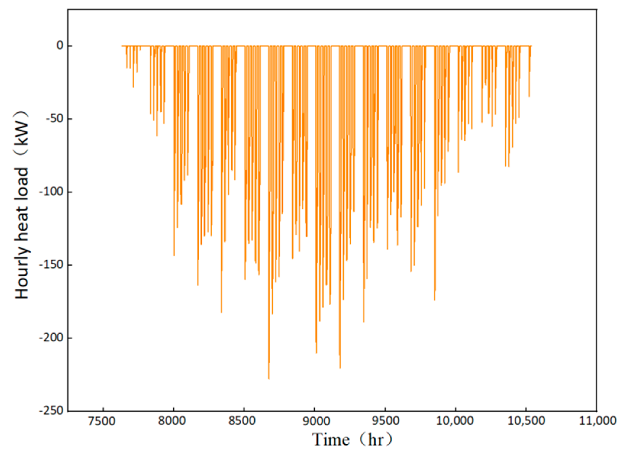
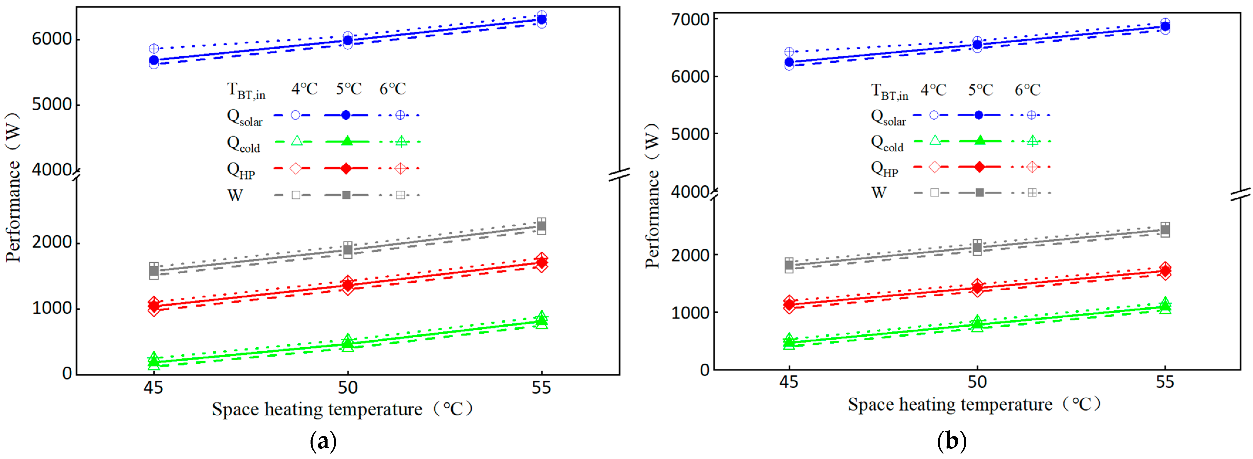
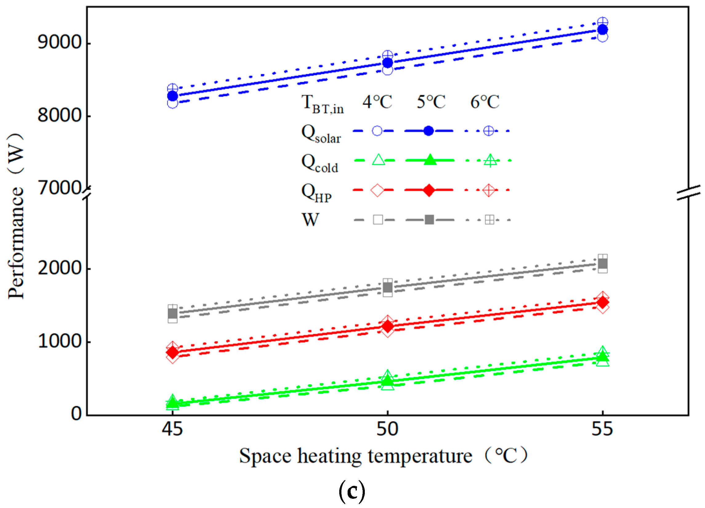
4.1. Ice Melting Performance Analysis

In analyzing the ice melting performance of SAPCHPs in three serial modes, it is necessary to determine the relationship between solar heat collection, ice melting heat consumption, heat pump heating and space heating, and to analyze the total energy consumption of different operation modes so as to compare the ice melting performance of these three operation modes.
Figure 6 shows the solar collector heat, ice melting heat consumption, heat pump unit heat production, and total system energy consumption for the three ice melting operation modes. During the period when the system is melting ice and supplying heat, the solar collector heat is relatively high, and the heat pump unit heat production and ice melting heat consumption are relatively low. The heat of the system melting ice and heating mainly comes from solar energy. The solar collector heat, ice melting heat consumption, heat pump unit heat production and total system energy consumption increase with the increase of space heating temperature and inlet temperature of the hot side fluid medium in the buffer tank [20].
Figure 6a shows the ice melting performance in the pure serial dual-source heat pump operation mode. During the 30 min of ice melting, as the space heating temperature increases, the heat pump unit heat production increases accordingly. Before switching to the ice melting mode, the PCM inevitably increases the ice thickness in order to provide more latent heat to the heat pump unit. Therefore, the PCM will require a corresponding increase in ice melting heat consumption when melting ice. In addition, in the pure serial dual-source heat pump operation mode, the solar collector heat is used to melt the ice first and then enter the heat pump unit to release the heat. As the heat consumption for ice melting and the heat production of the heat pump unit increase, the amount of solar energy collected increases accordingly.
Figure 6b shows the ice melting performance in the ice melting serial dual-source heat pump operation mode. Compared with mode 4, the solar energy collection, ice melting heat consumption, heat production of the heat pump unit and the total energy consumption of the system increase in mode 5. When the inlet temperature of the fluid medium on the hot side in the buffer tank increases, the solar heat collection amount increases while the flow rate of the fluid medium remains constant. In the ice melting serial dual-source heat pump operation mode, part of the solar collector heat is used for ice melting and part of it is used to provide heat for the heat pump unit [21]. In this case, the heat consumption of ice melting and the heat production of the heat pump unit will increase simultaneously.
Figure 6c shows the solar collector heat, ice melting heat consumption, heat production of the heat pump unit, and total system energy consumption for the affected serial dual-source heat pump operation mode. To ensure the steady-state operation of the system, the initial refrigerant fluctuation amount should be controlled within a reasonable range when the system switches operation modes. To meet the building heat load and system ice melting demand, the number of solar collectors for mode 6 is doubled compared to mode 4 and mode 5. Therefore, the investment for mode 6 will increase accordingly.

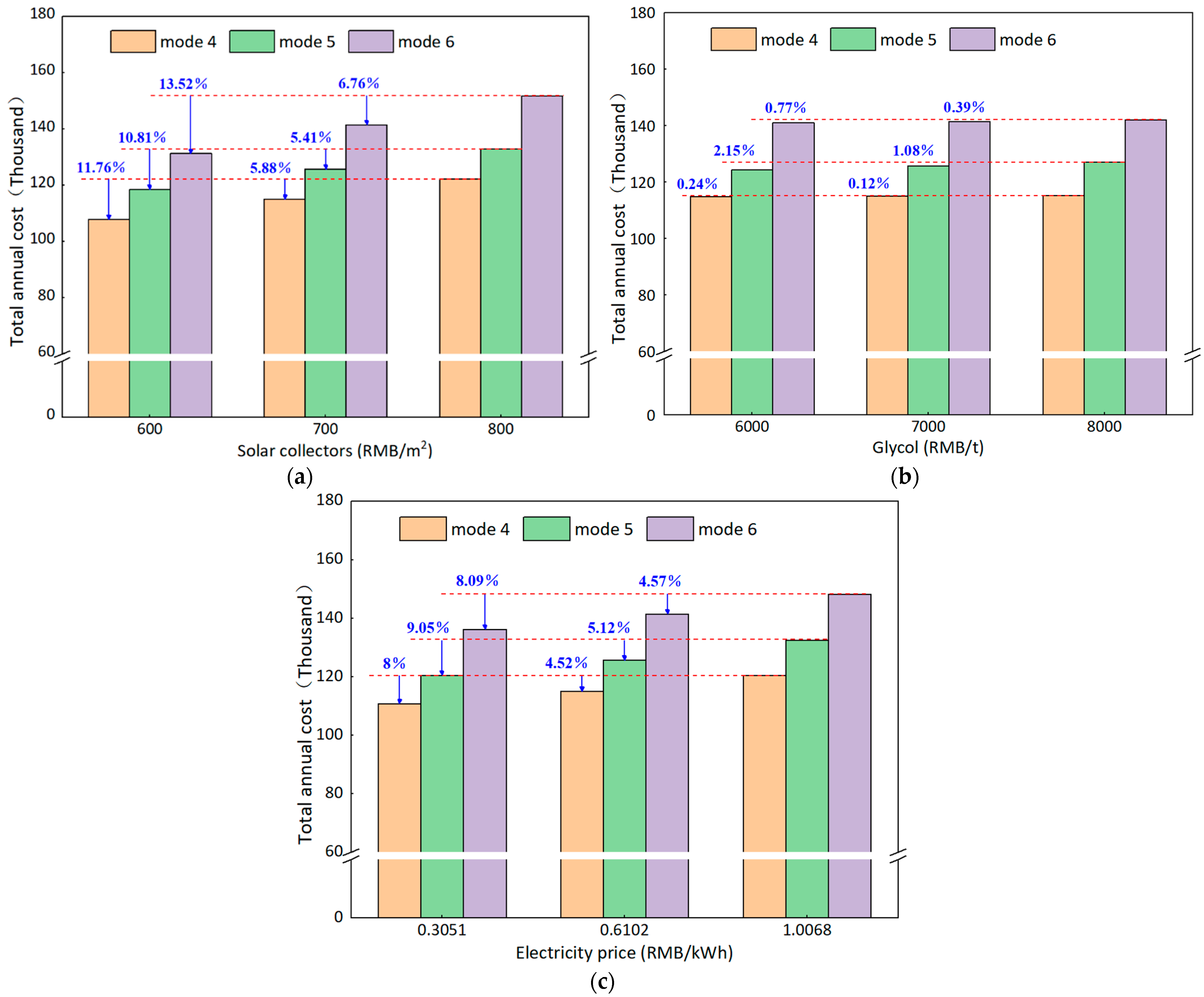
4.2. Economic Analysis of Ice Melting

When determining the optimal ice melting operation mode of the system, not only the ice melting performance and operation stability of the system, but also its economy should be considered. In order to cover the initial investment and operation cost, the total annual cost was used as the evaluation indicator of the economic operation of the system.
As can be seen from Figure 7, mode 6 has the highest annual total cost, followed by mode 5. However, mode 4 has the lowest annual total cost. Therefore, under the premise of only considering the system economy, the optimal ice melting operation mode is mode 4. In addition, changes in the price of solar collectors have the greatest impact on the total annual cost, and changes in the price of ethylene glycol have the least impact on the total annual cost. The investment in solar collectors accounts for a large proportion of the total system investment.
Figure 7a shows the changing trend of the annual total cost of the three ice melting modes when the price of solar collectors increases from six hundred RMB (100 RMB = 15 €) per square meter to eight hundred RMB per square meter. When the price of solar collectors increases by one hundred RMB per square meter, the total annual cost of mode 4, mode 5 and mode 6 increases by about 5.88%, 5.41% and 6.76%, respectively.
Figure 7b shows the changing trend of the annual total cost of the three ice melting modes when the price of ethylene glycol increases from six thousand RMB per ton to eight thousand RMB per ton. When the price of ethylene glycol increases by one thousand RMB per ton, the annual total cost of mode 4, mode 5 and mode 6 increases by about 0.12%, 1.08% and 0.39%, respectively. It can be seen that changes in the price of ethylene glycol have a greater impact on mode 5 because, compared with mode 4 and mode 6, the refrigerant flow required for mode 5 operation is the largest.
Figure 7c shows the influence trend of the peak-to-valley electricity price in Xi’an on the annual total cost of the three ice melting modes. The economic impact of electricity prices on the three ice melting modes is second only to solar collectors. As the peak hours of power consumption for industry and commerce in Xi’an are from 8:00 a.m. to 11:30 a.m. and 6:30 p.m. to 11:00 p.m., the valley period is from 11:00 p.m. to 7:00 a.m., and the rest of the time is the plain electricity price. Therefore, the office building in Xi’an uses the peak electricity price from 8 a.m. to 11:30 a.m. and the flat electricity price from 11:30 a.m. to 6 p.m., with relatively high operating costs.

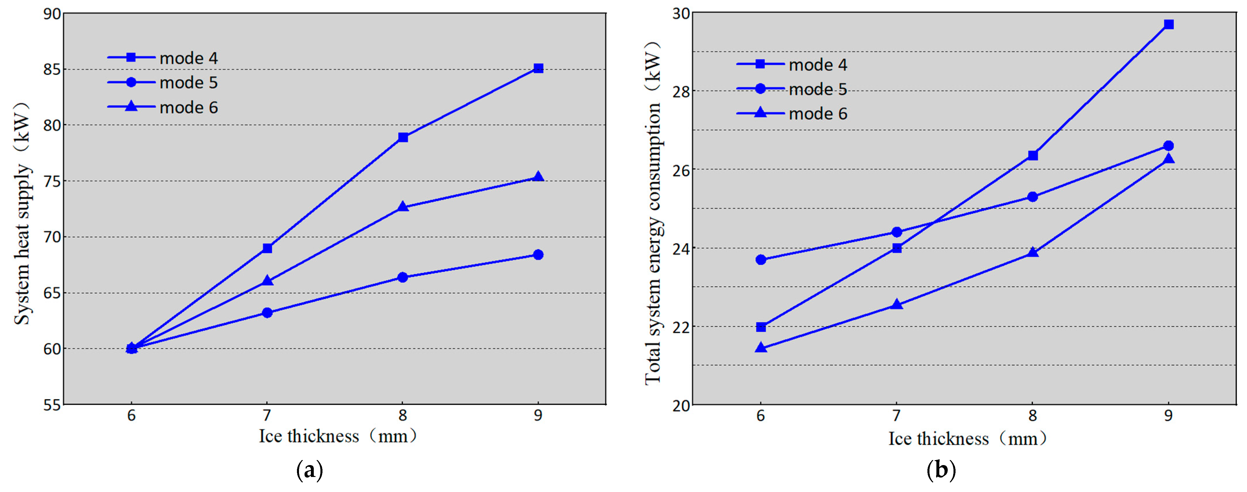
4.3. Effect of Ice Thickness on the Melting Performance of the System

The change of the PCM ice thickness will affect the heat gain from phase-change energy and the heat consumption of ice melting. In order to explore the effect of ice thickness on the ice melting performance of the system, the ice thickness was set to 6 mm, 7 mm, 8 mm and 9 mm respectively, and the input parameters of each system component in TRNSYS were changed. Figure 8 is obtained.
It can be observed from Figure 8a that the ice thickness is proportional to the system heat supply in the three serial ice melting operation modes. Under the premise of the same heat transfer temperature difference, in order to melt the thicker ice, the PCM will inevitably increase the refrigerant flow rate, so that the refrigerant flow rate entering the heat pump increases. Therefore, the heat extraction increases, and the system heat supply increases. However, when the ice thickness exceeds 8 mm, the increase in space heating of the SAPCHPs becomes smaller. In the early stage of ice melting, the ice on the PCM wall absorbed heat and gradually melted. The heat transfer from ice melting was dominant at the same time. With the passage of ice melting time, heat was transferred to the inside of the ice layer. The thermal resistance of the ice layer would hinder the transfer of heat, and the heat consumption of ice melting would increase. However, the heat transfer of ice melting was still dominant. When the ice layer reached a certain thickness, the thermal resistance of the ice layer played a larger role in the heat transfer process than the ice melting heat transfer. The thermal resistance of the ice layer was dominant at this time, and the heat transfer performance was greatly reduced [22]. Therefore, when the ice thickness exceeds 8 mm, in order to overcome the thermal resistance of the ice layer, the increase in the heat consumption required by the PCM for ice melting becomes larger, resulting in a decrease in the increase in space heating.
Figure 8b shows the effect of ice thickness on the power consumption of the system. The thicker the ice layer, the more heat it takes to melt the ice. Under the same ice melting heat transfer temperature difference, the PCM with thicker ice layer corresponded to a larger refrigerant flow rate during ice melting. In order to drive a larger flow of refrigerant, the rated power and rated flow of the water pump will be increased, and the system power consumption will increase. However, the increase in ice thickness has the greatest impact on the total system power consumption for mode 4.
Figure 8c shows the effect of ice thickness on the system COP. When the ice thickness was 6 mm, 7 mm, 8 mm and 9 mm, the system COP of the pure serial dual-source heat pump mode was about 2.72, 2.87, 2.99 and 2.86, respectively. The system COP of the ice melting serial dual-source heat pump mode was about 2.5, 2.59, 2.62 and 2.57, respectively. The system COP of the affected serial dual-source heat pump mode was about 2.78, 2.91, 3.02 and 2.86, respectively. Therefore, when the ice thickness is set to 8 mm, the system COP of the three serial ice melting operation modes reaches the maximum. During the 30 min of ice melting, there is a slight drop in the system COP of mode 5, and the data described in the figure are its average values. The COP of the affected system in the serial dual-source heat pump mode is larger compared to the pure serial dual-source heat pump mode and the ice melting serial dual-source heat pump mode.

5. Conclusions

(1)
The building heat load is simulated according to TRNSYS software, and the three ice melting operation modes are constructed. The performance of the three serial ice melting operation modes of the SAPCHPs are simulated under the premise of meeting the heating demand. During the period when the system is melting ice and supplying heat, the heat comes mainly from solar energy. The heat production of the heat pump unit and the heat consumption of the ice melting are relatively low.
(2)
In an economic analysis of solar collector price, ethylene glycol price, and electricity price for ice melting in the SAPCHPs. The change in the price of solar collectors has the greatest impact on the total annual cost, and the change in the price of ethylene glycol has the least impact on the total annual cost. When the price of solar collectors increases by one thousand RMB per square meter, the total annual cost of mode 4, mode 5 and mode 6 increases by about 5.88%, 5.41% and 6.76%, respectively. When the price of ethylene glycol increases by one thousand RMB per ton, the annual total cost of mode 4, mode 5 and mode 6 increases by about 0.12%, 1.08% and 0.39%, respectively.
(3)
When considering the effect of ice thickness on the system ice melting performance, the increase in space heating of the SAPCHPs becomes smaller and the increase in ice melting heat consumption becomes larger when the ice thickness exceeds 8 mm. Therefore, when the ice thickness is 8 mm, the system COP of the three serial ice melting modes of the SAPCHPs reaches the maximum. The affected serial dual-source heat pump mode has the largest system COP compared to the pure serial dual-source heat pump mode and the ice melting serial dual-source mode.
(4)
In this paper, the three serial ice melting modes of the SAPCHPs are investigated, their ice melting performances are simulated, their economics are calculated, and the effect of icing thickness on system operation is analyzed. However, the heating performance of SAPCHPs has not been studied. It is hoped that this paper will be useful in regards to future research.

Author Contributions

Conceptualization, Y.Y. (Yujuan Yang); methodology, Y.Y. (Yujuan Yang) and R.W.; formal analysis, Y.Y. (Yujuan Yang), R.W. and Y.Y. (Yuanbo Yue); investigation, Y.Y. (Yujuan Yang); data curation, R.W.; writing—original draft preparation, Y.Y. (Yujuan Yang); writing— review and editing, Y.Y. (Yujuan Yang), R.W. and Y.Y. (Yuanbo Yue); supervision, Y.Y. (Yujuan Yang). All authors have read and agreed to the published version of the manuscript.

Funding

This research received no external funding.

Institutional Review Board Statement

Not applicable.

Informed Consent Statement

Not applicable.

Data Availability Statement

Not applicable.

Acknowledgments

The authors acknowledge Qingdao KC blue new energy Co., Ltd. for providing patented technology to develop the cold water phase-change energy heat pump used in this study.

Conflicts of Interest

The authors declare no conflict of interest.

Nomenclature

Nomenclature Nomenclature
A0maximum of the solar collector effificiencyToutoutlet temperature (°C)
A1negative of the first-order coeffificient (W m−2 °C−2)ΔTthe temperature difference between the supply and return water of the system (°C)
A2negative of the second-order coeffificient (W m−2 °C−2)Wpower consumption of the system (W)
Agsolar collector area (m2) W ˙ the amount of electricity consumed by the heat pump (W)
ACoperating cost(A/P·i·n)c recovery factor
b1safety factor 1(P/F·i·n)c discount factor
b2safety factor 2Greek symbols
Cpspecific heat capacity (J kg−1 °C−1)ηefficiency (%)
G ˙ flow rate (m3 h−1) η ˙ ssolar collector thermal effificiency (%)
Hhead (m)ρdensity (kg m−3)
ΔHgsystem resistance loss along the way (m)Subscripts
ΔHbloss of local resistance of the system (m)cworking medium in cold water phase-change machine
IIinitial investmentfjauxiliary heater
Ipglobal radiation incident on solar collector (W m−2)iith node
LRcalculate period-end recovery of liquidityjjth node
m ˙ mass flow (kg m−1)lflluid
P ˙ power (W)qwater pump
Q ˙ heat exchange (W)sworking medium in solar collector
Q ˙ uheat exchange before the heat pump (W)Acronym
Q ˙ mthe thermal load of the system (W)BTbuffer tank
Rcalculate the salvage value of the fixed asset recovered at the end of the periodHPheat pump
ttime (s)PCMcold water phase-change machine
Ttemperature (°C)SAPCHPssolar-assisted cold water phase-change energy heat pump system
TACtotal annual costTRNSYStransient system simulation program
Taoutdoor temperature (°C)WPCHPscold water phase-change energy heat pump system
Tininlet temperature (°C)

References

  1. Guo, Y.; Yu, B. Academician Jin Yong: Green and low-carbon transformation is the core of future economic activities. Environ. Prot. 2022, 50, 33–34. [Google Scholar]
  2. Luo, R.; Zhang, A.; Li, C. Waste heat recovery system of waste bath hot water based on water source heat pump. Int. Core J. Eng. 2021, 7, 586–589. [Google Scholar]
  3. Zhang, L.; Zhou, M.; Yang, C.; Li, Y.; Fu, Z.; Wang, J.; Jin, L. Evaluation and optimization of water source heat pump for district heating: A case study in steel plant. Int. J. Energy Res. 2019, 44, 9399–9413. [Google Scholar] [CrossRef]
  4. Jung, Y.; Kim, J.; Kim, H.; Nam, Y.; Cho, H.; Lee, H. Comprehensive multi-criteria evaluation of water source heat pump systems in terms of building type, water source, and water intake distance. Energy Build. 2021, 236, 110765. [Google Scholar] [CrossRef]
  5. Wu, R.; Zhang, C.; Sun, D.; Ren, N. Energy saving and environmental assessment of heat pump systems for surface water sources in rivers and lakes. J. Harbin Inst. Technol. 2008, 2, 226–229. [Google Scholar]
  6. Xu, H.; Zhou, B.; Li, G.; Hua, G.; Kong, X. Research on low-carbon operation optimization of regional integrated energy system with water source heat pump. Integr. Smart Energy 2022, 44, 39–48. [Google Scholar]
  7. Hu, W. Applicability of source water source heat pump system in hot summer and warm winter area. Int. J. Mech. Eng. Appl. 2019, 7, 123–130. [Google Scholar] [CrossRef]
  8. Guo, L.; Shan, W. Water source heat pump’s stuck problems and solutions. J. Phys. Conf. Ser. 2022, 2174, 012084. [Google Scholar] [CrossRef]
  9. Qian, J.; Sun, D.; Zhang, J. Comprehensive heating performance analysis of new collection and solidification heat pump technology and system. J. Dalian Univ. Technol. 2011, 51, 244–249. [Google Scholar]
  10. Yue, Y.; Wu, R.; Zhu, H. Cold water phase change energy heat pump system and energy consumption characteristics. Therm. Power Eng. 2020, 35, 259–264, 274. [Google Scholar]
  11. Zheng, J.; Wu, R. Technical solution of heat pump system for extracting cold water solidification heat. HVAC 2016, 46, 140–142. [Google Scholar]
  12. Wu, X. Simulation and Experimental Study of Cold Water Phase Change Energy Heat Pump System. Master’s Thesis, Qingdao University, Qingdao, China, 2019. [Google Scholar]
  13. Yue, Y. Operation Characteristics and Engineering Experimental Study of Cold Water Phase Change Energy Heat Pump System. Master’s Thesis, Qingdao University, Qingdao, China, 2020. [Google Scholar]
  14. Liu, Z.; Yue, Y.; Wu, R. Cold water phase change energy heat pump system and its heat transfer performance. HVAC 2020, 50, 94–98. [Google Scholar]
  15. Wu, X.; Wu, R.; Wu, H. Experimental analysis of the performance of cold water phase change energy heat pump system. J. Qingdao Univ. 2019, 34, 105–110. [Google Scholar]
  16. Cheng, Y.; Wu, R.; Yu, H. Yue, Y. Analysis of the best working conditions and energy consumption of the coupling system between the cold water phase change machine and the air source heat pump. Therm. Power Eng. 2022, 37, 168–175. [Google Scholar]
  17. Xu, Y.; Meng, X.; Han, X. Numerical simulation of the icing condition in an ice storage heat exchanger under steady-state conditions. Refrig. Technol. 2021, 44, 51–58. [Google Scholar]
  18. Wu, X.; Wu, R.; Wu, H. Analysis of the economy and energy consumption of cold water phase change energy heat pump systems. J. Qingdao Univ. 2018, 31, 138–142. [Google Scholar]
  19. Abdulrahman, D.; Fabian, O.; Michele, B.J.; Wolfgang, S. Advances in seasonal thermal energy storage for solar district heating applications: A critical review on large scale hot-water tank and pit thermal energy storage systems. Appl. Energy 2019, 239, 296–315. [Google Scholar]
  20. Liu, Z.; Wu, R.; Yu, H. Water phase change energy heat pump heating system operation test. HVAC 2019, 49, 96–100. [Google Scholar]
  21. Zhan, H.; Wu, R.; Yu, H. Load analysis and area optimization of day heating solar heat pump system. Therm. Power Eng. 2022, 37, 124–130. [Google Scholar]
  22. Zhang, C.; Sun, D. Thermal analysis of plane freeze solidification phase transformation under convective conditions on both sides. J. Sol. Energy Eng. 2009, 30, 75–80. [Google Scholar]
Figure 1. The operating principle of SAPCHPs.
Energies 15 05905 g001
Figure 2. Solar irradiation during the heating season.
Energies 15 05905 g002
Figure 3. Office and ambient temperature during the heating season.
Energies 15 05905 g003
Figure 4. Hourly heat load during the heating season.
Energies 15 05905 g004
Figure 5. (a) The pure serial dual-source heat pump operating mode; (b) the ice melting serial dual-source heat pump operating mode; (c) the affected serial dual-source heat pump operating mode.
Energies 15 05905 g005aEnergies 15 05905 g005b
Figure 6. (a) Performance in mode 4 mode; (b) Performance in the mode 5 mode; (c) Performance in the mode 6 mode.
Energies 15 05905 g006aEnergies 15 05905 g006b
Figure 7. (a) The impact of solar collectors price on the total annual cost; (b) the impact of glycol price on the total annual cost; (c) the impact of electricity price on the total annual cost.
Energies 15 05905 g007
Figure 8. (a) The effect of ice thickness on system heat supply; (b) the effect of ice thickness on system power consumption; (c) the effect of ice thickness on the system COP.
Energies 15 05905 g008aEnergies 15 05905 g008b
Table 1. SAPCHPs operating modes.
Operating MannerModeTurn on the PumpTurn off the PumpStart the ValveStop the Valve
single cold water phase-change heat pump11, 2, 4, 63, 54, 51, 2, 3, 6, IMV1, IMV2
solar heat pump22, 3, 61, 4, 51, 32, 4, 5, 6, IMV1, IMV2
parallel dual-source heat pump31, 2, 3, 4, 651, 3, 4, 52, 6, IMV1, IMV2
pure serial dual-source heat pump42, 3, 4, 61, 52, 3, 51, 4, 6, IMV1, IMV2
ice melting serial dual-source heat pump52, 3, 4, 61, 51, 2, 3, 64, 5, IMV1, IMV2
affected serial dual-source heat pump62, 3, 4, 61, 52, 4, 5, 61, 3, IMV1, IMV2
solar ice melting72, 3, 41, 5, 62, 61, 3, 4, 5, IMV1, IMV2
heat melting of the heat exchanger85, 61, 2, 3, 4IMV1, IMV21, 2, 3, 4, 5, 6
Table 2. Parameters of the main equipment.
TypeParameterValue
5bHot working fluidEthylene glycol water solution (40.5% by volume)
Specific heat of hot side fluid3.401 kJ kg−1 °C−1
Cold working fluidEthylene glycol water solution (40.5% by volume)
Specific heat of cold side fluid3.401 kJ kg−1 °C−1
73Working fluidEthylene glycol water solution (40.5% by volume)
Fluid specific heat capacity3.401 kJ kg−1 °C−1
Inlet flowrate1.57 kg s−1
Total collector array area210 m2 (mode 6: 315 m2)
Incidence angle45°
Collector slope40°
668Source specific heat3.401 kJ kg−1 °C−1
Load specific heat4.19 kJ kg−1 °C−1
Inlet source temperature1 °C
Source flow rate1.57 kg s−1
Inlet load temperature45 °C
Load flow rate0.51 kg s−1
Publisher’s Note: MDPI stays neutral with regard to jurisdictional claims in published maps and institutional affiliations.

