The magnet flux density is essential for investigating the machine demagnetization characteristics and evaluating the machine demagnetization withstand capability. This is because, under the same operating condition, the machine with higher magnet flux density will generally have better demagnetization withstand capability. It is known that magnet flux density (B
m) depends on the reluctance of the magnetic circuit (R), the magnetomotive force (MMF) generated by PMs (F
m) and armature current (F
c), and can be calculated by:
where Φ and A are the flux in the magnet and magnet area, respectively.
F
m and F
c can be described by:
where B
r, μ
0, μ
r, L
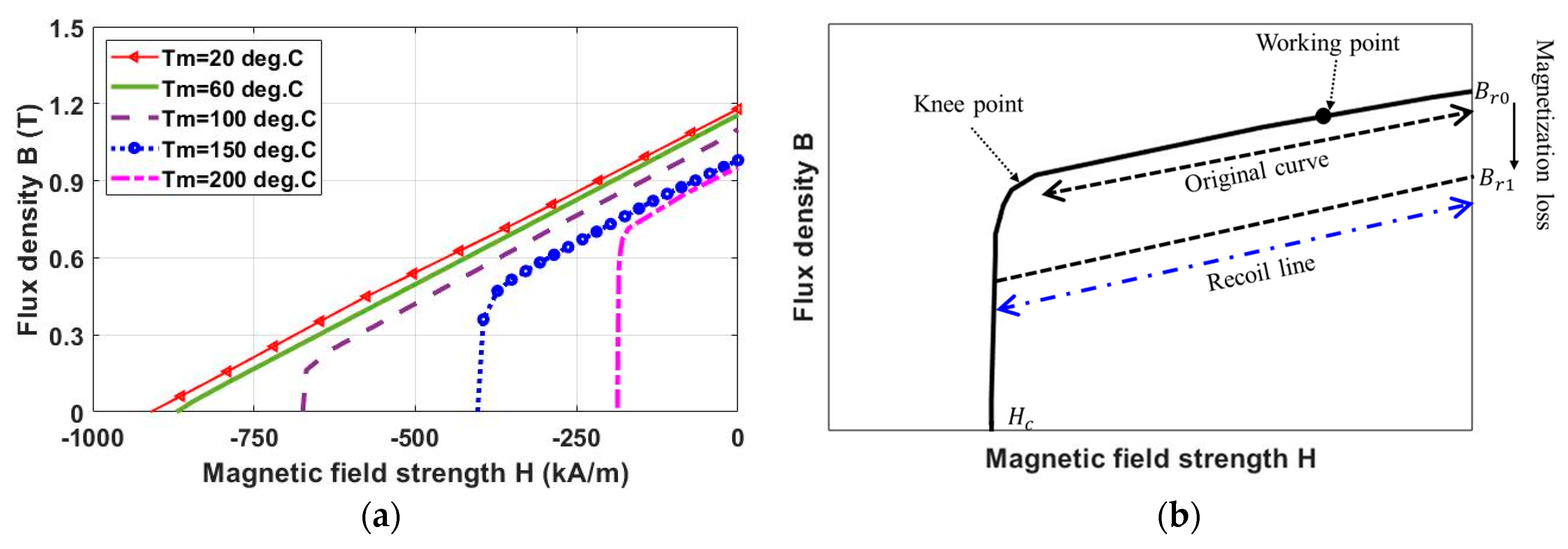
mag, N, and i are the magnet remanence, vacuum permeability, magnet relative permeability, magnet thickness, number of turns and magnitude of armature current. It is worth noting that the magnet properties, e.g., remanence (B
r) and coercivity (H
c), are temperature-dependent as described by [
18]:
where T
0 is the reference temperature and α
1, α
2, β
1 and β
2 are temperature-dependent coefficients. α
1, α
2, β
1 and β
2 for the chosen magnet material in this paper are −1.2 × 10
−3, −1.5 × 10
−9, −6.9 × 10
−3 and 1.17 × 10
−5, respectively.
According to Equations (1)–(3), the magnet flux density variation can be contributed from three sources:
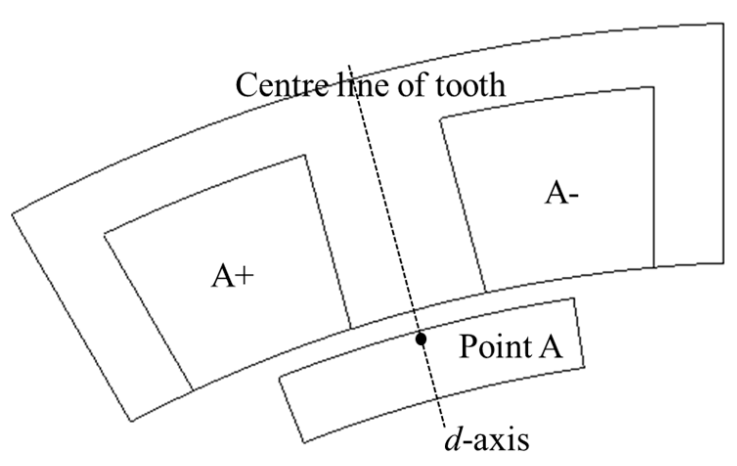
In order to investigate the magnet demagnetization, the points along the center line within a PM (as shown in
Figure 6) have been chosen. This is mainly due to the fact that the magnet in this region is more easily affected by demagnetization than other regions [
5]. It is worth noting that, in order to separate the influence of the above three sources on the magnet demagnetization, a range of magnet temperatures will be used first in this section without adopting coupled EM-thermal modelling, which will be investigated in
Section 2.2.4 for more accurate temperature prediction.
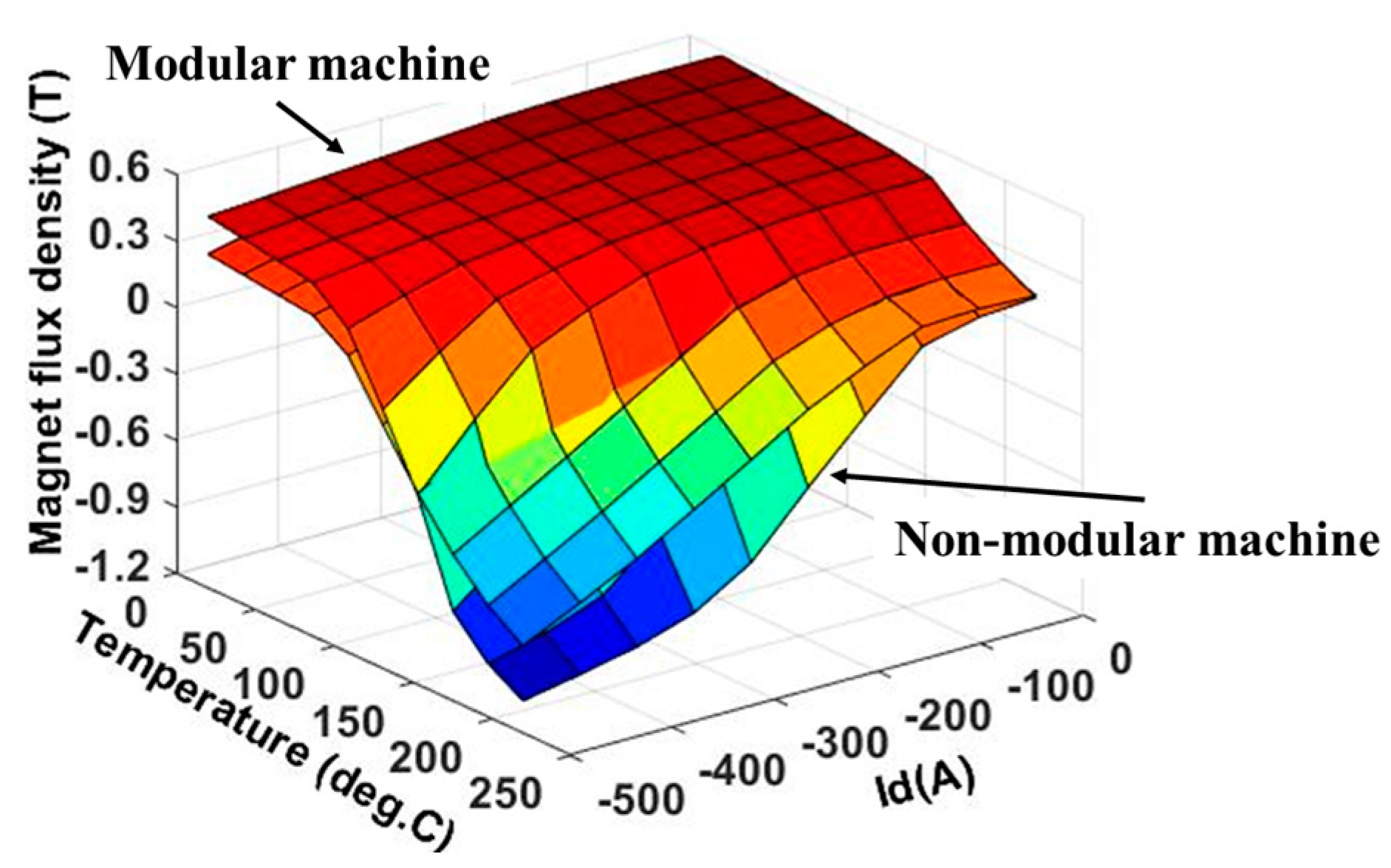
Without considering the magnet temperature variation, temperature rise in particular, the magnet demagnetization is mainly due to the MMFs produced by the PMs and armature currents, especially the negative d-axis current, as shown in
Figure 7. It is found that, at a magnet operating temperature of 20 °C, when the load current is smaller than a critical value, e.g., 200 A for the modular machine and 300 A for the non-modular machine, the minimum flux density is almost constant when the d-axis current reduces. After the critical value, the minimum magnet flux density reduces almost linearly with reducing d-axis current. Compared with the non-modular machine, the modular machine is found to be able to improve the minimum magnet flux density at different load currents. This means that the introduced flux gaps can improve the demagnetization withstand capability.
The flux density versus rotor position for the modular and non-modular machines is also investigated, as shown in
Figure 8. It is found that, if the current is smaller than the critical value, the minimum magnet flux density is reached when the center line of the PM is aligned with the center line of the slot (rotor position 2 in
Figure 8). In addition, the values of the minimum flux density are almost the same for different currents. On the contrary, when the current is larger than the critical value, the minimum magnet flux density can be reached when the center line of the PM is aligned with the center line of the tooth (rotor position 1 in
Figure 8). In addition, when the selected PM rotates to the flux gap region, the magnet flux density will reduce until the center line of the PM is aligned with the center line of the flux gap (rotor position 3 in
Figure 8). This magnet flux density variation is caused by the combined influence between machine topology, MMFs generated by PMs, and armature currents, which will be detailed in the following sections.
2.2.1. PM Field Only
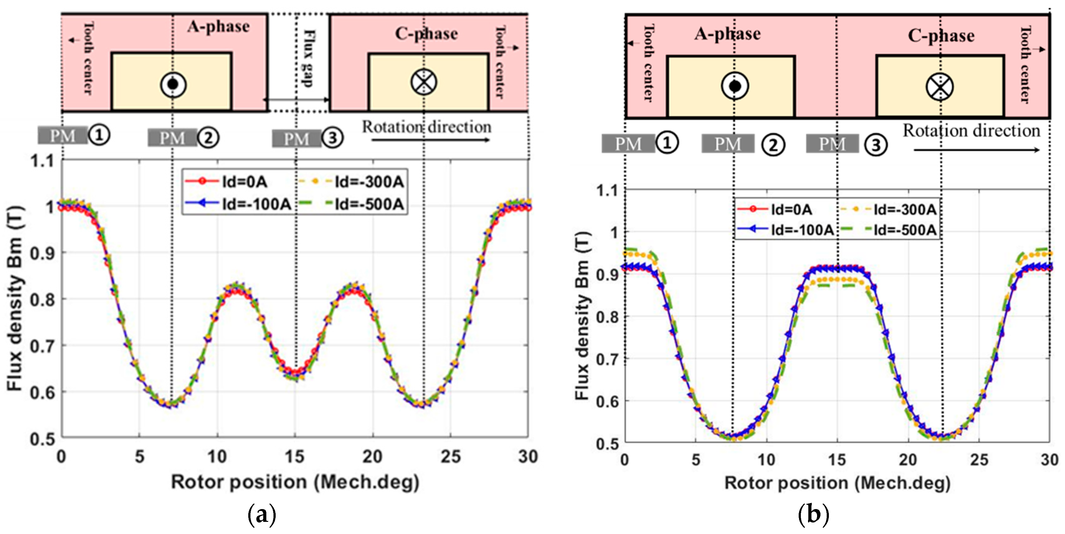
In order to evaluate the influence of demagnetization caused by only the PM field while under the influence of negative d-axis current, the modular and non-modular machines have been simulated at a PM temperature of 20 °C. By adopting the FP method, the armature field has been removed and the magnet flux density variation due to the PM field for both investigated machines are shown in
Figure 9. Without the armature field, the magnet flux density only depends on the reluctance of the magnetic circuit and the PM MMF (FM). It is found that, due to the non-linear characteristics of the iron core, reducing the d-axis current increase its relative permeability (μ
r); therefore, reduces the reluctance while increasing the magnet flux density. The variation in magnet flux density is significant for the non-modular machine as show in
Figure 9b. However, it is found that, the flux density variation for the modular machine under different load currents is almost the same, as shown in
Figure 9a. This means that, the introduced flux gaps in the modular machine can significantly reduce the PM flux density variation caused by the variation of iron core permeability.
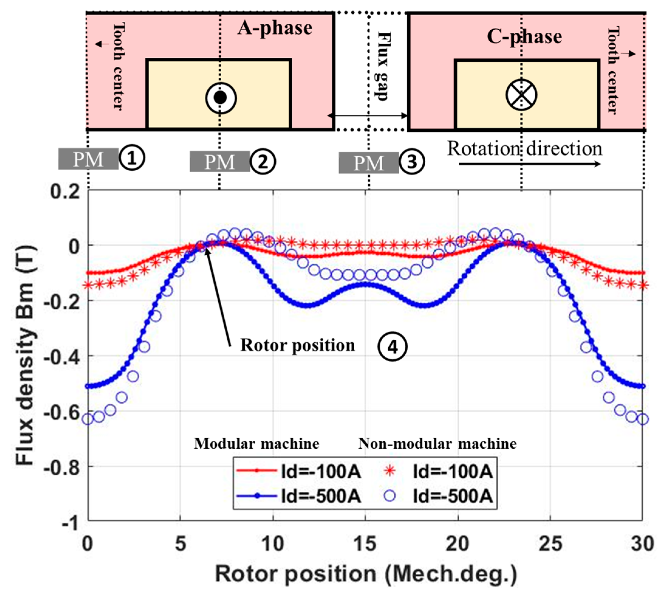
For both the investigated machines, the maximum flux density is reached at the initial rotor position, i.e., the center line of the magnet is aligned with the center line of the tooth (rotor position 1 in
Figure 9a). This is because the effective airgap length, and therefore the reluctance, are minimum when the rotor is at position 1. When the rotor rotates and the selected magnet is facing the slot opening, the reluctance increases because of the small relative permeability of the copper wires (μ
r = 1) in the stator slot. Therefore, the magnet flux density reduces and reaches its minimum value when the center line of the magnet is aligned with the center line of the slot opening (rotor position 2 in
Figure 9a). The introduced flux gaps have the same effect as the slot openings, which also reduce the magnet flux density when the selected magnet rotates to the flux gap region. The magnet flux density will keep reducing until the center line of the magnet is aligned with the center line of the flux gap (rotor position 3 as shown in
Figure 9a).
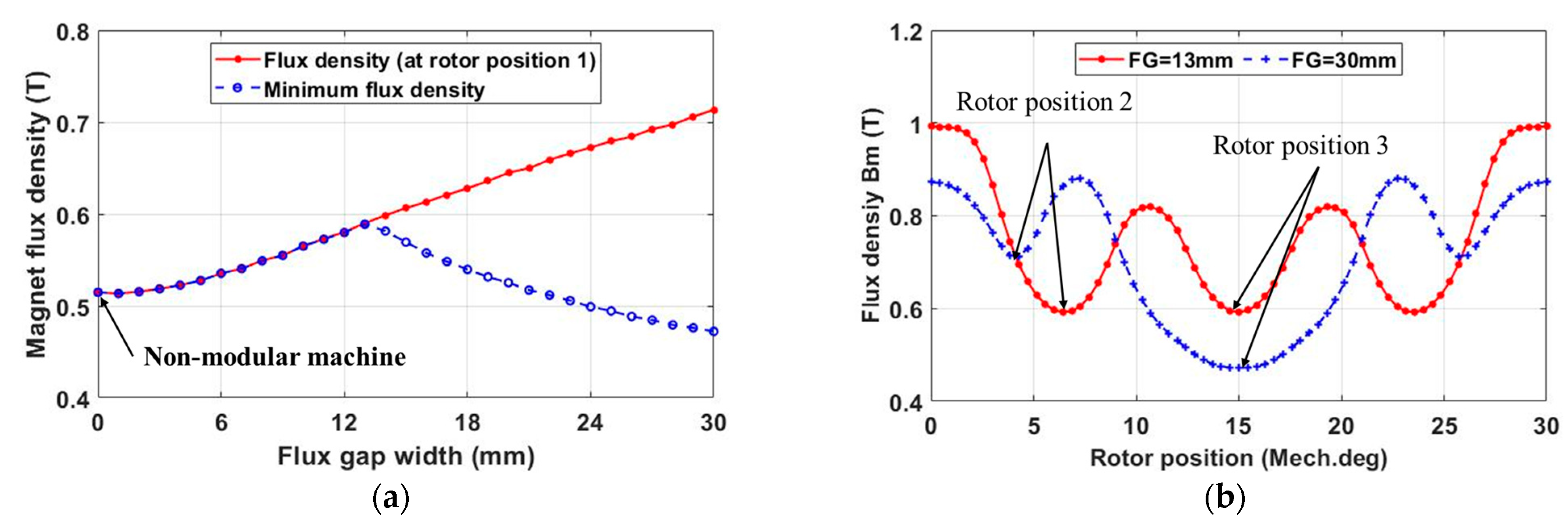
The results above are for a single flux gap width (10 mm), the minimum magnet flux density variation against the flux gap width has also been investigated, as shown in
Figure 10a. It is found that, when the flux gap width is smaller than 13 mm, an increasing flux gap width leads to increased minimum flux density. This means improved magnet demagnetization withstand capability. The reason is that, increasing flux gap width leads to reduced slot opening, and hence, a reduced effective airgap length at rotor position 2. As a result, the minimum flux density at position 2 will be increased, as shown by the red curve in
Figure 10b. However, when the flux gap width is larger than a critical value (13 mm for the investigated modular machine in this paper), the minimum magnet flux density reduces with increased flux gap width. This is because the flux gap has the same effect with the slot openings. If the flux gap width is large enough (13 mm for the investigated modular machine), the magnet flux density at rotor position 3 will be smaller than that at rotor position 2 due to the larger effective airgap length, as shown by the blue curve in
Figure 10b. This means that an optimal flux gap width (13 mm) can be found from the magnet demagnetization withstand capability point of view.
2.2.2. Armature Field Only
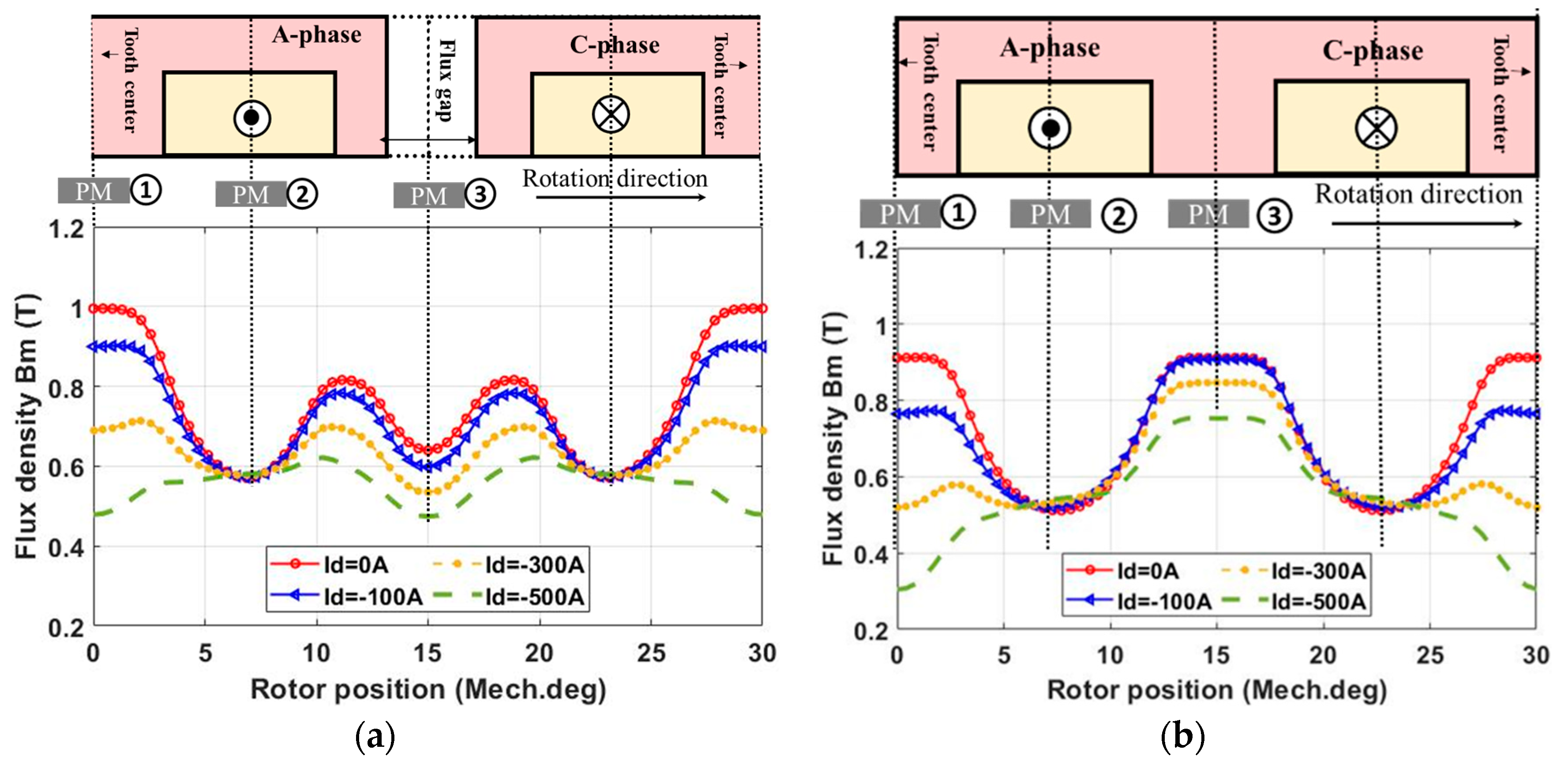
Apart from the PM field in the previous section, the applied armature currents can also generate demagnetizing MMF. Again, using the FP method, the magnet flux density (at point A) due to only the armature field against the load current has been calculated, as shown in
Figure 11. The magnet flux density now depends on the load current, and the effective airgap length, as described by Equations (1) and (2). As a result, for both the modular and non-modular machines, at the initial rotor position 1 where the d-axis is aligned with the center line of the tooth of the A-phase, the magnitude of the A-phase current reaches its maximum value, and the effective airgap length is the smallest. This leads to the most significant demagnetization, and hence, the minimum magnet flux density. When the rotor rotates towards the slot opening, the effective airgap length is increased. Together with a reduced A-phase current, the magnet flux density generated by the applied armature field at point A is increased. However, when the rotor rotates by 90 electrical degrees, i.e., 45/7 ≈ 6.4 mechanical degrees, named as rotor position 4 in this paper, the A-phase current is 0 A, while the B-phase current is equal to minus C-phase current. Hence, the magnet flux density at point A is 0 T.
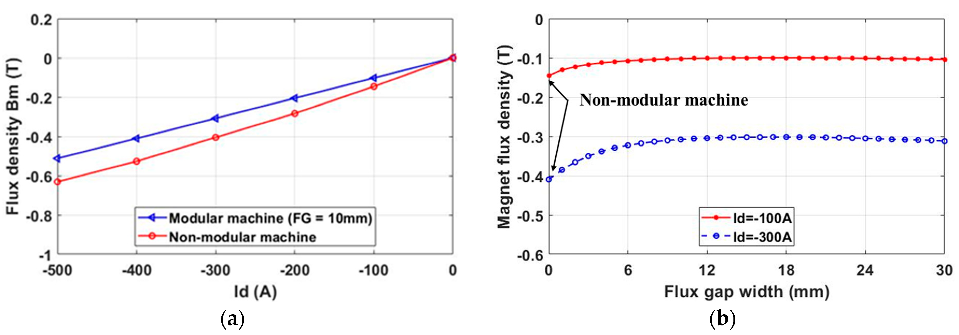
According to Equation (2), the armature MMF is proportional to the current amplitude. Therefore, when the current amplitude increases, the minimum magnet flux density reduces, as shown in
Figure 12a. This is true for both the modular and non-modular machines. However, the modular machine is able to increase the minimum magnet flux density, which results from the increased effective airgap length due to the introduced flux gaps as mentioned in the previous section. However, this increase in magnet flux density is insignificant when the flux gap width is larger than 10 mm, as shown in
Figure 12b. In addition, the improved minimum magnet flux density for the modular machine reveals that the demagnetization caused by armature MMF in the modular machine can also be mitigated by the introduced flux gaps. This is similar to the demagnetization caused by the PM MMF in previous section.
2.2.4. Demagnetization with Coupled EM-Thermal Modelling
As discussed in previous sections, it is found that the machine topologies, load current and temperature rise can significantly affect the flux density distribution within PMs. This will, in turn, affect the losses, e.g., stator and rotor iron core losses, PM eddy current loss, and EM torque. Together with the increase in copper loss due to the temperature-dependent electrical resistivity of copper [the coefficient is 3.69 × 10
−3/°C [
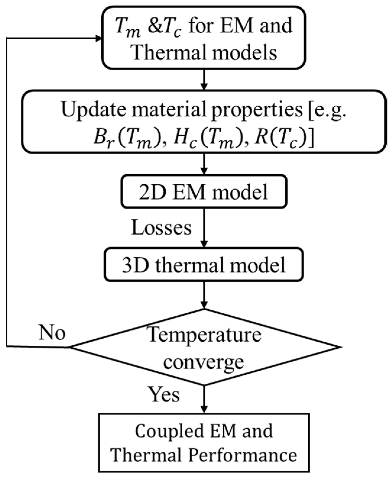
13] (p. 76), the variation of losses caused by demagnetization will also lead to machine temperature variation, which will again affect the EM’s performance. Therefore, the coupled EM-thermal modelling, as described by the flowchart shown in
Figure 2, is essential to account for the interaction between the EM and thermal performance. In this section, the coupled EM-thermal modelling is implemented for both investigated machines. Three operating conditions are considered for the investigations, e.g., condition 1 (rated current I
d = 0 A and I
q = 100 A), condition 2 (flux weakening − I
d = I
q = 50
A), and condition 3 (3 times the rated current I
d = 0 A and I
q = 300 A).
Some assumptions need to be made for the coupled EM-thermal modelling such as:
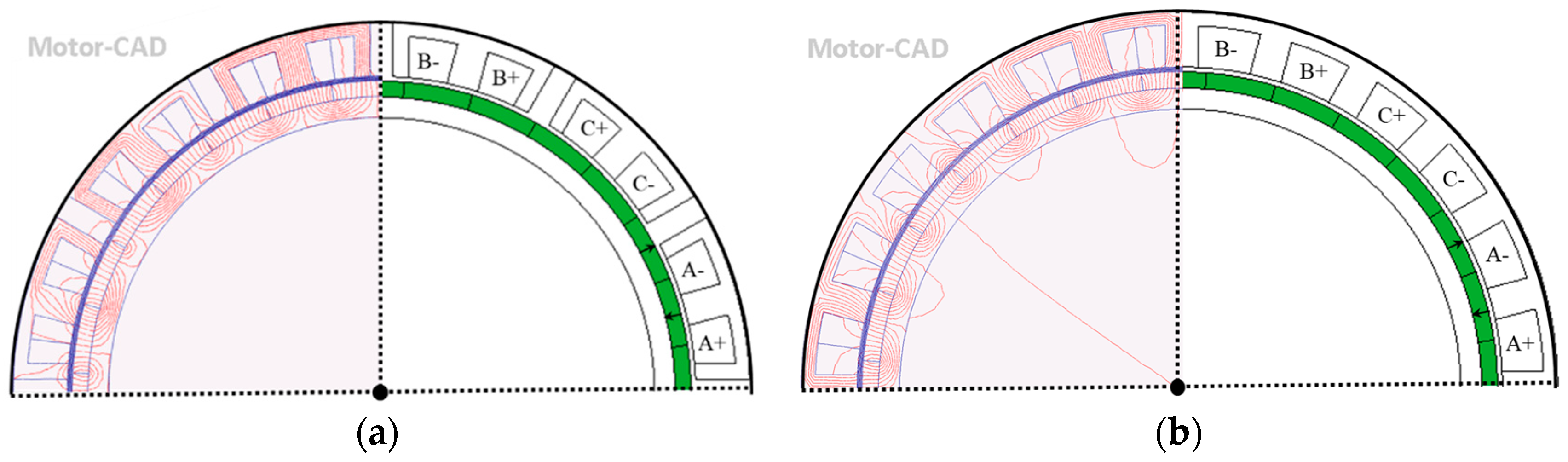
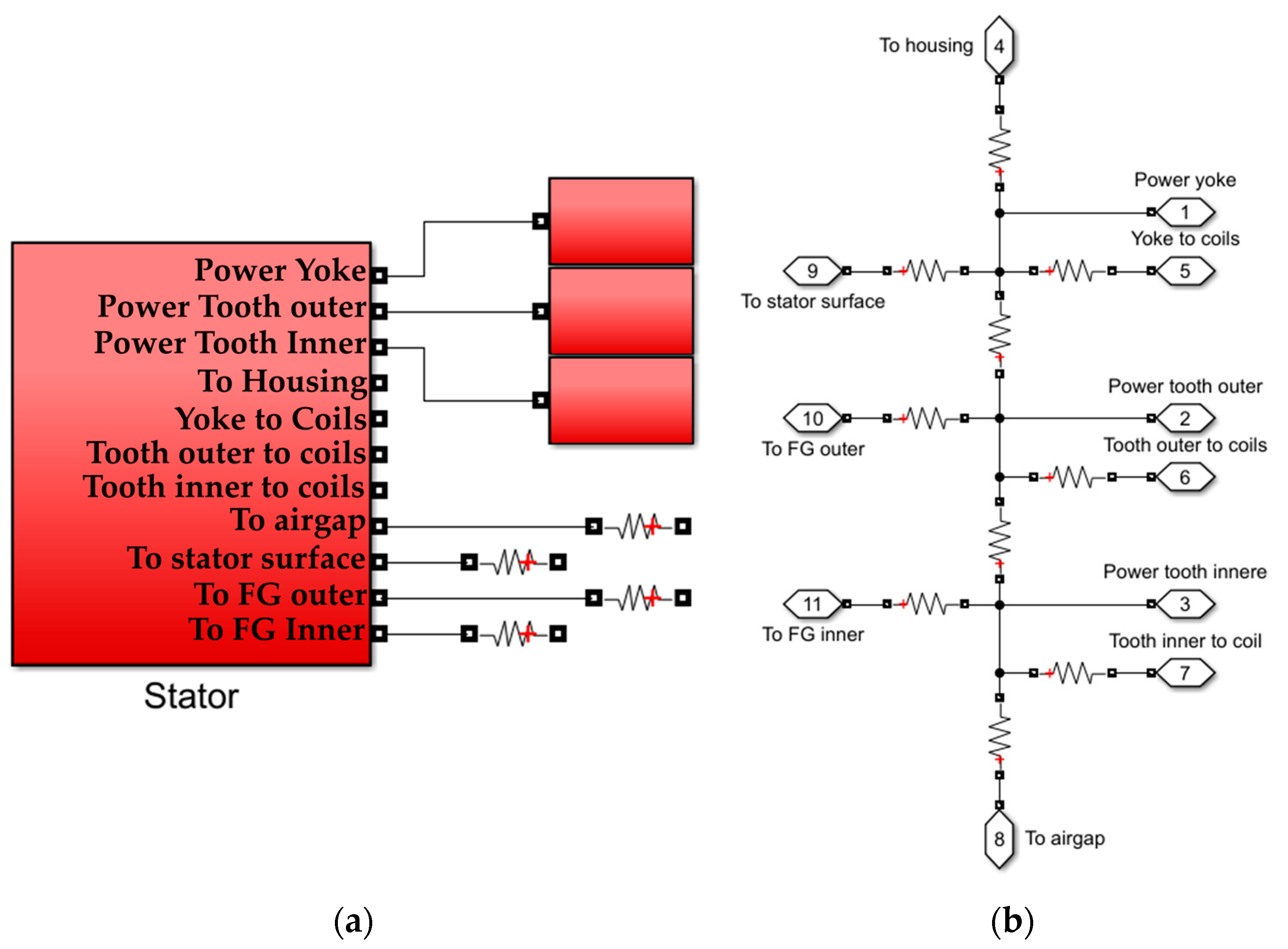
It is worth noting that the coupled EM-thermal model is quite computationally intensive. Therefore, instead of using a 3D finite element (FE) thermal or 3D computational fluid dynamics (CFD) model, 3D lumped parameter thermal network (LPTN) models for both the modular and non-modular machines have been developed based on the models in Motor-CAD. Different from the non-modular machine, the LPTN of the modular machine should include extra equivalent thermal resistances to represent the heat convection at the flux gap surfaces. The stator segments with heat convection are shown in
Figure 14a, and the heat conduction in the stator is shown in
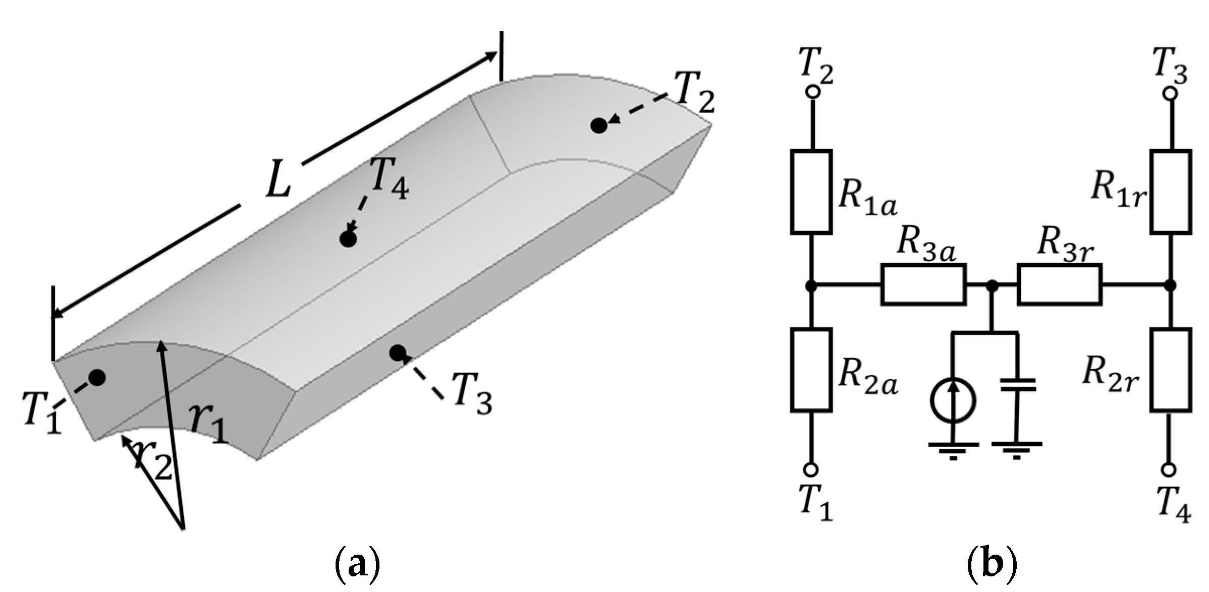
Figure 14b. The rotor thermal network is not shown as it is the same as that of the non-modular machine. The equivalent thermal resistance of the segmental stators and new topologies of the windings for the modular machines should be re-calculated. For example, the segmental stator back-iron and active winding will be considered as cylindrical components with angular spans
as shown in
Figure 15a, and its equivalent thermal network is shown in
Figure 15b. The equivalent thermal resistances are derived by [
20]:
where r
1, r
2 and L are the radius of the outer surface, radius of the inner surface, and stack length, respectively. It is worth noting that, if the components are without heat generation, resistance R
3r and R
3a is equal to 0. The equivalent thermal resistance of the heat convection at flux gap surfaces is also derived by:
where h is the convection coefficient at the flux gap surfaces, which are calculated by CFD.
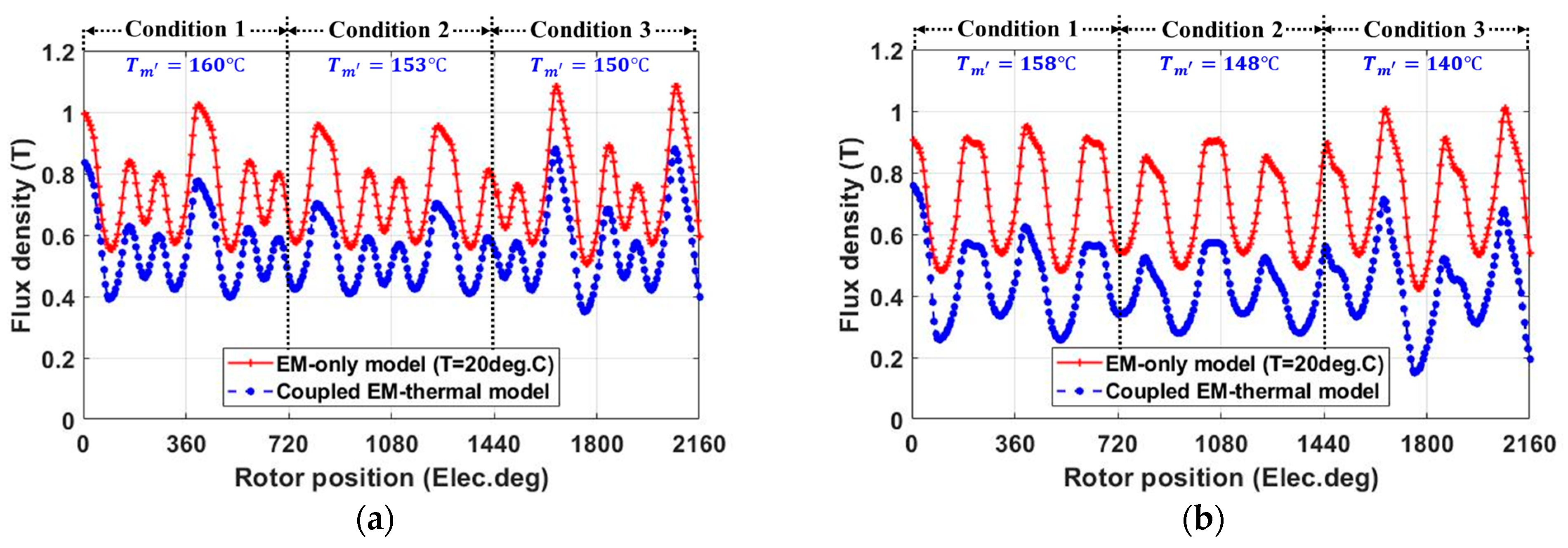
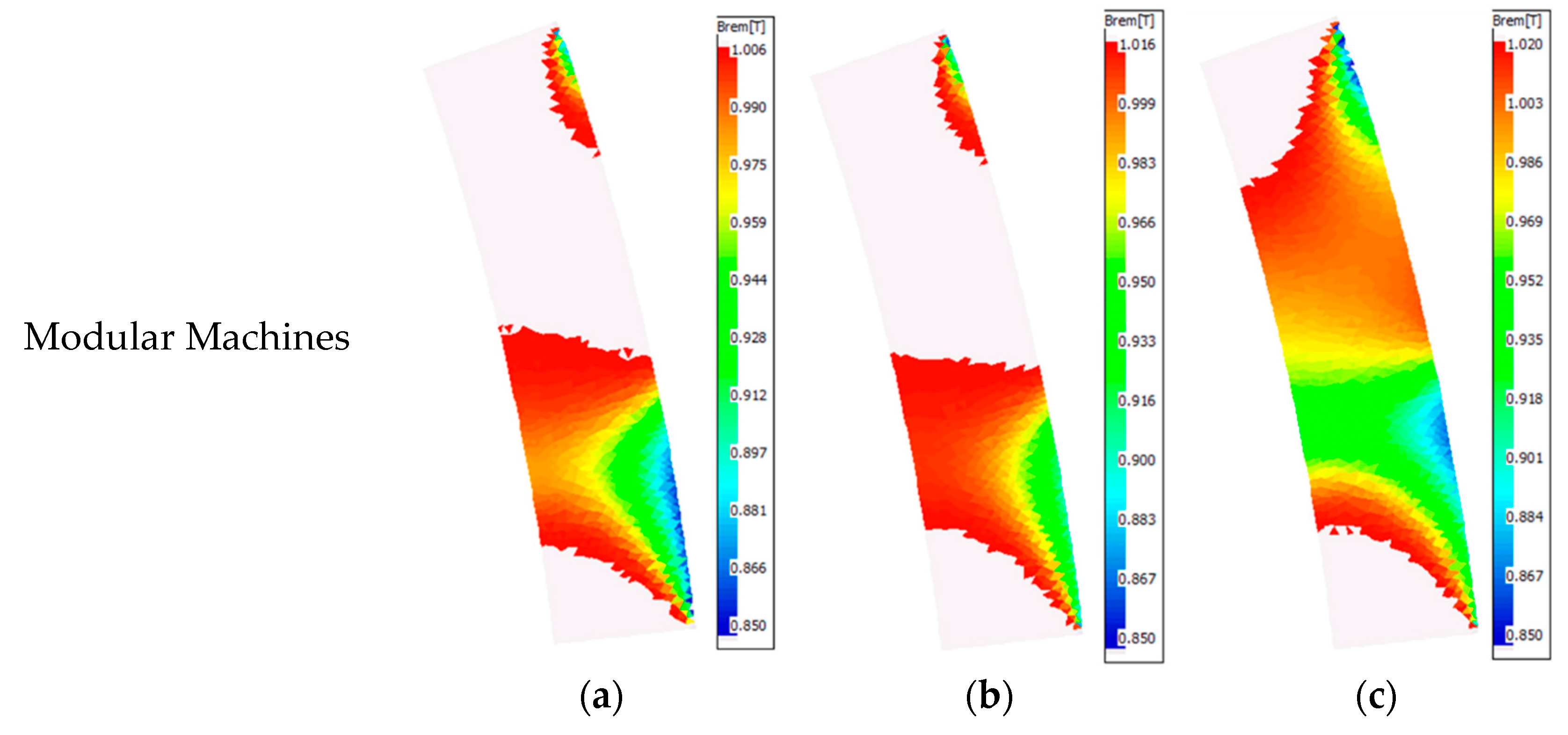
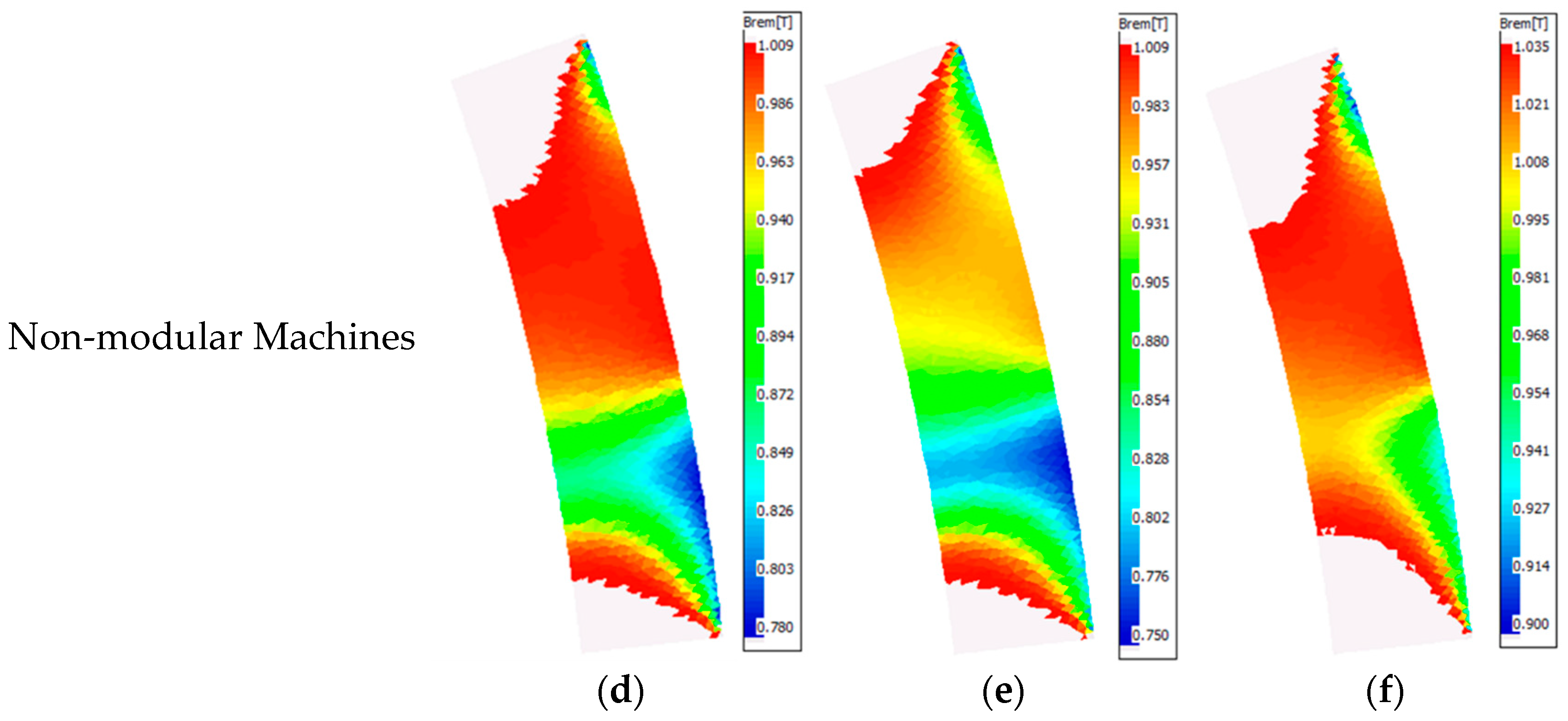
Using the coupled EM-thermal model, the average PM and coil temperatures for both investigated machines have been obtained, as shown in
Table 3. Due to the magnet’s temperature rise, the magnet flux density is reduced for both the investigated machines under different operating conditions, as shown in
Figure 16. In addition, the magnet flux density in condition 2 is slightly smaller than that in condition 1. This reduction is mainly due to the introduced d-axis current for flux weakening. However, the amplitude of the d-axis current in condition 2 is relatively small, and therefore, the demagnetization caused by the armature field is only marginal.
It is worth noting that the PM eddy current loss is proportional to the magnet flux density variation rate (dB
b/dt). Compared with the non-modular machine, the magnet flux density variation rate of the modular machine is smaller, as shown in
Figure 16. This is because the increase in the effective airgap length, caused by the introduced flux gaps, can reduce the magnet flux density variation rate, and hence, can reduce the PM eddy current loss, as shown in
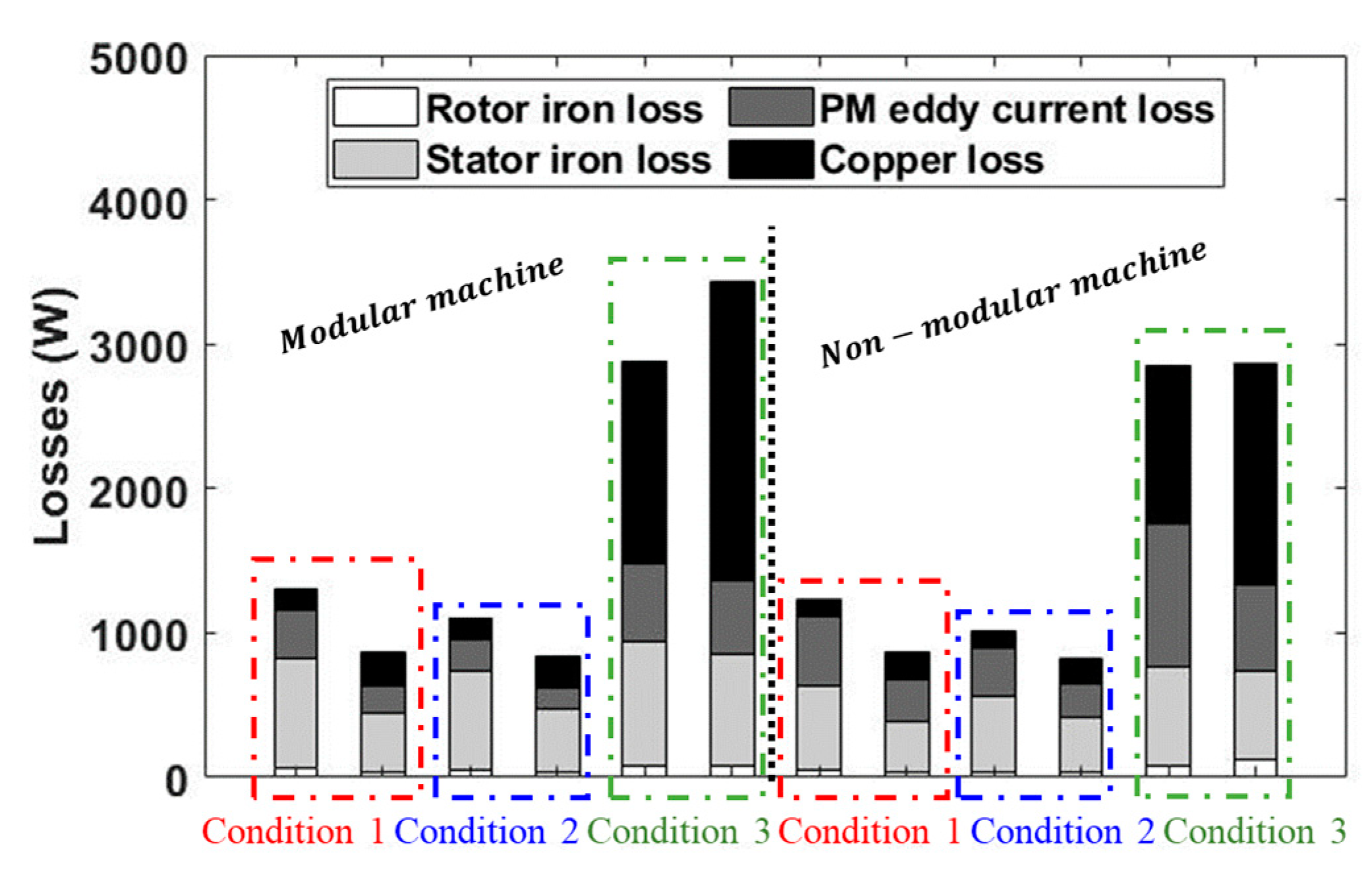
Figure 17. This decrease can be more significant when the machines operate under overload conditions, e.g., three times the rated current.
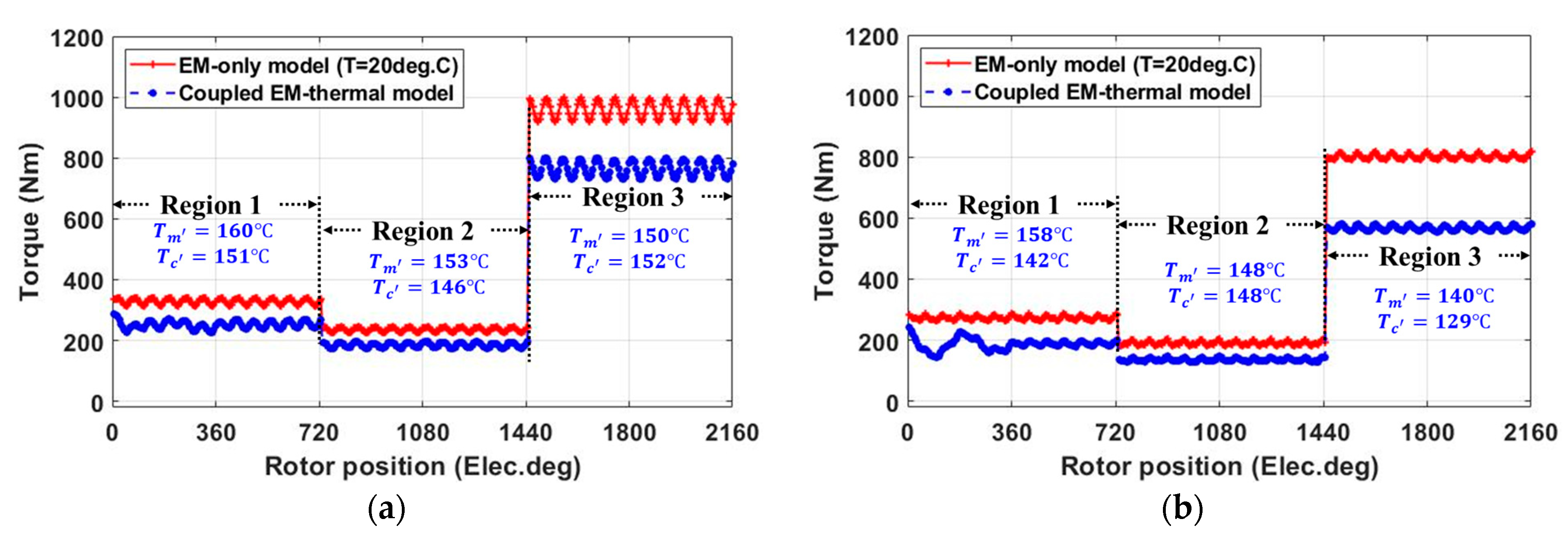
In addition, with the coupled EM-thermal model, the losses for different load conditions, including the PM eddy current loss, and stator and rotor iron core losses, are all reduced for both of the investigated machines. This is also due to the demagnetization caused by the PM’s temperature rise. Furthermore, due to higher copper loss resulting from the reduced slot area, the temperatures within the modular machine are higher than those within the non-modular machine under a peak phase current of 100 A (conditions 1 and 2). For example, with the introduced flux gaps, the PM temperature increases from 158 °C and 148 °C to 160 °C and 153 °C for the conditions 1 and 2, respectively. When the machines operate the condition 3, e.g., I
q = 300 A, the advantage of flux gaps in reducing the PM eddy current loss is more evident, as shown in
Figure 17. However, the increase in copper loss can also be more significant due to increased load current. This results in a higher coil temperature, which can further increase the copper loss. As a result, the modular machine has a higher copper loss and coil temperature (increase from 129 °C (non-modular) to 152 °C (modular)). In addition, the PM temperature of the modular machine is also affected by this high copper loss, increasing from 140 °C (non-modular) to 150 °C (modular). However, it is worth noting that these results are obtained under the condition that the number of turns per phase and the phase current are the same between the modular and non-modular machines. Given the fact that the modular machine can achieve higher average torque, then, if under the same average torque conditions, the copper loss of the modular machine will be smaller than that of the non-modular counterpart [
4]. This will lead to lower coil and PM temperatures within the modular machine.
With the coupled EM-thermal modelling, the partial irreversible demagnetization has also been investigated for both the modular and non-modular machines. The irreversibly demagnetized areas (colored), where the remanence is reduced, are shown in
Figure 18. It is found that both machines will experience irreversible demagnetization, but the modular machine has a smaller irreversible demagnetization region than the non-modular machine. This means that the introduced flux gaps can improve the demagnetization withstand capability under different load conditions.
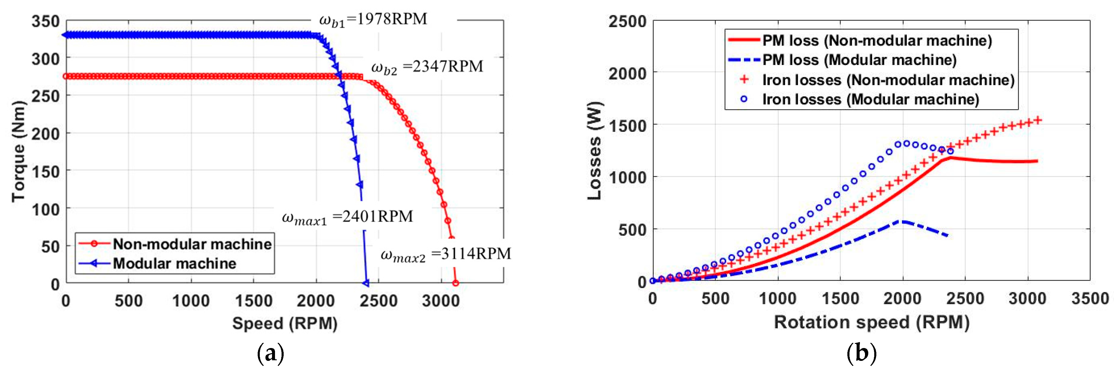
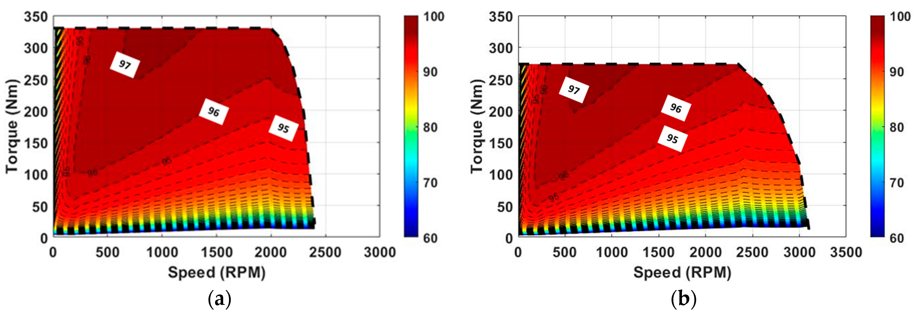
Torque, as one of the most important EM performances for the machines, is also affected by the demagnetization. Compared with the EM-only modelling, the torque of the modular and non-modular machine calculated by using the coupled EM-thermal modelling is lower. This is mainly due to the demagnetization caused by the PM temperature rise, as shown in
Figure 19. Even though the modular machine has higher PM temperature due to copper loss, the decrease in torque is less significant than the non-modular machine. It is shown that, the improved demagnetization withstand capability and reduced PM eddy current loss due to flux gaps allow the modular machines to have better EM performance.


