3.2. Method for Estimation of Values of Traction Energy Consumption of Stops of the Model Train and Construction of Energy-Saving Freight Train Paths
The first part of the timetabling experiment serves the purpose of an estimation of the traction energy consumption for each possible stop of the model freight train, in each intermediate station of a particular line, for both directions separately. For practical reasons (no necessity for stop), double-track sections of the line 340 (introduced below) were excluded.
For an estimation of traction energy consumption, the calculation of tractive work in FBS/iPLAN timetabling software [
1] for the analogous type of the locomotive (Vectron Dual Mode, as well as Stadler Euro Dual) was used as follows. First, the train path for the model train from the beginning to the end station of a particular line and direction, without any intermediate stop, was constructed. Stops in the beginning and the end stations were designed (for a change in the propulsion and, if needed, for change in the direction of the train), since stations were considered as all of the points on the line, where the passing (crossing) of two trains of opposite directions was practically possible. Intermediate stations with a distance from the beginning of the line are presented in
Table 1,
Table 2 and
Table 3. For each station in the tables, the length of the longest, practically usable, station track for crossing of the model train is listed, with mostly passenger trains. Practical usability indicates that there are departure signals for both directions and that the stop of a freight train does not hinder boarding and alighting of the passengers in the case of a stop of a passenger train. The main station track (that directly continues from and to the rail line) is always excluded. The length of the longest usable station track is for practical reasons (visibility of the departure signal and reserve for inaccuracy of the stop) shortened by 20 m compared to the distance between departure signals, and listed in the official plans of the stations by Správa železnic [
23]. These resulting lengths are listed in
Table 1,
Table 2 and
Table 3.
For each chosen line, intermediate station and direction, the energy consumption of the stopping of the model train will be calculated as follows:
where
Estop,l,AB,X is calculated as the traction energy consumption necessary for the stop and following acceleration of the model train on the line with number l, in station X in the direction from A to B;
Eline,l,AB,X is calculated as the traction energy consumption of the journey of the model train on the line with number l, in the direction from A to B, with stops only in A, B, and X;
Eline,l,AB,0 is calculated as the traction energy consumption of the journey of the model train on the line with number l, in the direction from A to B, with stops only in A and B.
After the traction energy consumption of the stop of the model train in each station and direction is calculated, appropriate stations for passing the model freight train and passenger train (with periodic timetable as a rule) can be chosen. If no considered station restricts the length of the train, then a set of stations with the lowest sum of traction energy consumption of the stops that enable a feasible freight train path within a given periodic passenger timetable, is chosen. If one considered station restricts the length of the model train, the neighboring station with comparably low traction energy consumption (for particular direction) is chosen instead. If no replacement of the “short station” with neighboring station enables a feasible freight train path, one or more of the other passing stations are replaced in an analogous way. If no replacement enables a feasible freight train path, the model train has to be shortened in a particular direction in order not to exceed the maximum train length of the most restricting passing station.
Choice of appropriate passing stations for the model freight train with variable (higher) number of wagons is verified by sensitivity analysis in
Section 4.3, after the presentation of the results of the timetabling experiment.
3.4. Rail Lines Chosen for the Experiment
The aim of this part of the paper is to analyze the possibilities of operation of dual locomotives on selected lines, taking into consideration the additional energy consumption caused by running uphill or by the necessary stops and acceleration afterwards.
The authors decided to select three lines on the Czech railway network with different gradient and directional ratios, which are able to illustrate the possibilities of deployment of dual locomotives on a sufficiently differentiated sample. For this purpose, three categories of lines were chosen according to their gradient profiles—hilly line, flat line, and flat line with a significant peak in the middle. From each category, it was decided to select the most suitable line according to the following criteria:
Intensity of freight transport and its potential (lines of TEN-T network or lines of national importance according to the categorization of the Czech Railway Infrastructure Administration—Správa železnic). Lines with regular and heavy freight traffic are preferred.
Non-electrified line (or not the entire length of the line) linked in at least one end to an electrified mainline (25 kV 50 Hz AC).
The line is not ending—it connects at least two other lines.
The usable track length in all stations (excluding passenger switches) is at least 400 m (ideally more).
The capacity of the line is not significantly used by the intensive suburban passenger traffic.
Based on these criteria, the authors tested the consumption of traction energy on three non-electrified rail lines linked in at least one end to an electrified mainline (25 kV 50 Hz AC). Each rail line can be characterized by different types of longitudinal profile (see
Figure 1,
Figure 2 and
Figure 3). Each line is numbered according to the official passenger timetable sheets issued by Czech Railway Infrastructure Administration (Správa železnic) [
25].
Figure 1.
Longitudinal profile of the rail line 180 (data: [
1,
26]). Source: Authors.
Figure 1.
Longitudinal profile of the rail line 180 (data: [
1,
26]). Source: Authors.
Table 1.
Intermediate stations of the single-track line 180 Plzeň–Domažlice–Furth im Wald. (data: [
1,
23,
26]). Source: Authors.
Table 1.
Intermediate stations of the single-track line 180 Plzeň–Domažlice–Furth im Wald. (data: [
1,
23,
26]). Source: Authors.
| Station | Maximum Train Length [m] | Distance from the Beginning Station [km] |
|---|
| Plzeň hl. n. N. Hospoda 1 | No station track | 4.353 |
| Vejprnice | 709 | 7.721 |
| Nýřany | 568 | 13.459 |
| Výh Chotěšov | 731 | 20.526 |
| Stod | 560 | 25.306 |
| Holýšov | 637 | 32.866 |
| Staňkov | 527 | 39.145 |
| Blížejov | 803 | 47.284 |
| Výh Radonice | 653 | 52.536 |
| Domažlice | 725 | 58.392 |
| Česká Kubice | 547 | 69.474 |
Figure 2.
Longitudinal profile of the rail line 246 (data: [
1,
27]). Source: Authors.
Figure 2.
Longitudinal profile of the rail line 246 (data: [
1,
27]). Source: Authors.
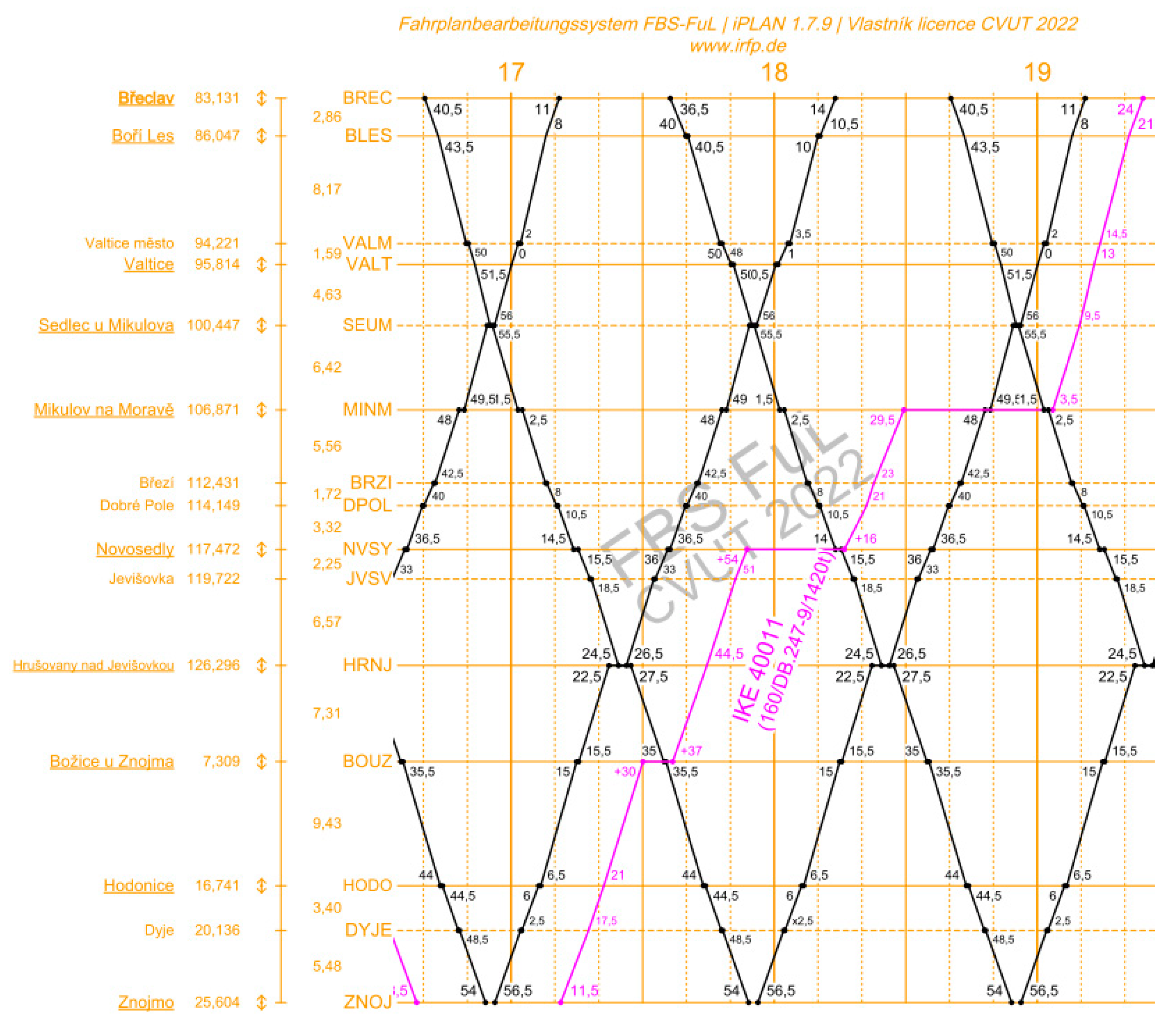
Table 2.
Intermediate stations of the single-track section of the line 246 Břeclav–Znojmo (data: [
1,
23,
27]). Source: Authors.
Table 2.
Intermediate stations of the single-track section of the line 246 Břeclav–Znojmo (data: [
1,
23,
27]). Source: Authors.
| Station | Maximum Train Length [m] | Distance from the Beginning Station [km] |
|---|
| Boří les | 591 | 2.862 |
| Valtice | 584 | 12.629 |
| Sedlec u Mikulova 1 | 180 | 17.262 |
| Mikulov na Moravě | 963 | 23.686 |
| Novosedly | 401 | 34.287 |
| Hrušovany n. J.-Šanov | 411 | 43.111 |
| Božice u Znojma | 502 | 50.420 |
| Hodonice | 609 | 59.852 |
Figure 3.
Longitudinal profile of the rail line 340 (data: [
1,
28]). Source: Authors.
Figure 3.
Longitudinal profile of the rail line 340 (data: [
1,
28]). Source: Authors.
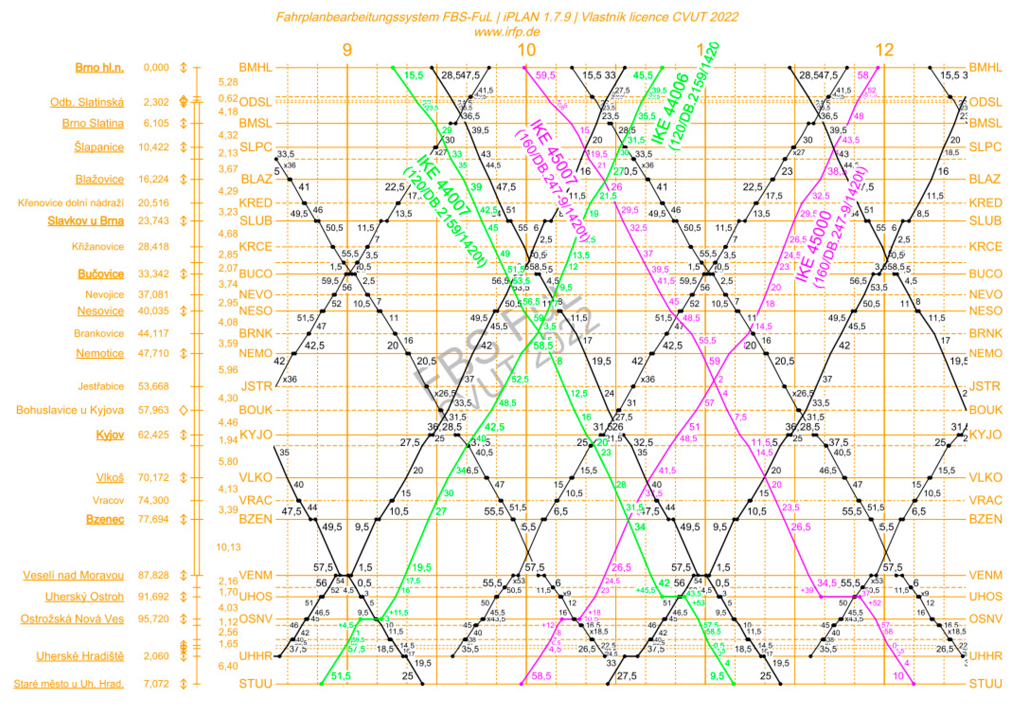
Table 3.
Intermediate stations of the single-track section of the line 340 Staré Město u U. H.–Brno (data: [
1,
23,
28]). Source: Authors.
Table 3.
Intermediate stations of the single-track section of the line 340 Staré Město u U. H.–Brno (data: [
1,
23,
28]). Source: Authors.
| Station | Maximum Train Length [m] | Distance from the Beginning Station [km] |
|---|
| Uherské Hradiště 1 | 377 | 5.012 |
| Ostrožská Nová Ves | 596 | 11.734 |
| Uherský Ostroh | 568 | 15.762 |
The first, single-track, rail line 180 connects Pilsen (located in Berounka valley) and Regensburg (located in Danube valley), both with approximately equal altitude. It overcomes hilly Cham-Furth Depression (Czech: Všerubská vrchovina), located between mountain ranges, and thus there are long uphill and downhill sections that increase the consumption of traction energy. At the other end of the line, there is a connection to the German 15 kV 16.7 Hz AC supply system at Regensburg station. In the paper, the analysis is carried out on the section from the starting station Plzeň to the border station Furth im Wald, located on the Czech-German border, with the highest elevation and the top station (Česká Kubice).
The second, mostly double-track, rail line 340 connects the second largest Czech city Brno and regional centre Uherské Hradiště in south-eastern Moravia. This line is located mostly in flat terrain of southern Moravia, except for the pass between Ždánický les and Chřiby highlands.
The third, single-track, rail line 246 connecting Břeclav and Znojmo, lies in predominantly flat terrain.
For practical reasons (short station tracks due to determination for passenger trains), stations Sedlec u Mikulova (line 240) and Uherské Hradiště (line 340) will be neglected in further calculations (see
Table 2 and
Table 3). However, for freight transport, these stations are of secondary importance.
3.4.1. Hilly Line (180)
This is a typical line in the region of Central Europe, which includes flat but also challenging sections with inclines. The maximum gradient is up to 12 per mille in crucial sections. Therefore, the permissible load limit is significantly limited by these restrictive sections. Gradients are in both directions.
For comparison purposes, the 81.154 km long line section from Plzeň via Domažlice in western Bohemia to the German border station Furth im Wald was selected as a sample line in this category. The whole length of the line is non-electrified, except for a short section in Pilsen (about 2 km), equipped with 25 kV 50 Hz AC power system. However, in the long term, the entire line should be covered by the same power system; the section from the state border to Germany should be covered by a German 15 kV 16.7 Hz AC system.
3.4.2. Flat Line (246)
The representative in this category is the line Břeclav–Znojmo, leading through the flat landscape in the southern part of Czechia, along the state border with Austria. This 68.725 km long line is characterized by a favorable longitudinal profile with minimal gradients. This makes it possible to transport considerably higher load volumes with one locomotive. In most of the length of the line, there are flat sections with a maximum gradient of 5 to 7 per mile. As well as in the case of the first line, the line is currently non-electrified, except for the starting station Břeclav, located under the 25 kV 50 Hz AC power supply system. On the other hand, the second end station Znojmo is equipped with a 15 kV 16.7 Hz AC power system, which is used in neighboring Austria. In this case, there are also plans to electrify the line with 25 kV 50 Hz AC system in the future.
3.4.3. Flat Line with Significant Peak in the Middle (340)
The third category represents lines that run through predominantly flat areas but have one significant peak that limits the maximum permissible train weight. There is a considerable number of these lines in Central Europe.
An example for this last category of lines is the 111.431 km long line Brno–Veselí nad Moravou–Staré Město u Uherského Hradiště, located in the south-eastern part of Czechia. Among the three lines presented, it is specific in that it is electrified in the section between Brno railway junction and Blažovice station (the first 20 km), again with a 25 kV 50 Hz AC power supply system. From Blažovice to the end of the line, the line is non-electrified, but the final station Staré Město u Uherského Hradiště is again on the electrified line, also under the 25 kV 50 Hz system. This line is located mostly in the flat terrain of southern Moravia, except for the pass between Ždánický les and Chřiby highlands. For this reason, the line in question is also very suitable for the deployment of dual vehicles, which can use the overhead catenary in sections where it already exists, and thus reduce diesel consumption. In addition, modern dual locomotives usually allow for switching between dependent and independent traction modes directly while running.
3.5. Model Trainset and Construction of Train Paths
The reference trainset consists of 20 container wagons (type Sgnss-x); for simplicity, the trainset is considered as homogeneous and composed only of these wagons with a unit weight of 78 tons (the average weight of a wagon loaded with two 40-foot containers). Therefore, the total length of the trainset (with the longer of the two considered locomotives) is 419 m, and the hauled (towed) weight is 1420 tons. Two types of dual locomotives—Siemens Vectron Dual Mode (G15 variant) and Stadler Euro Dual (HVLE variant) —transport this set on the reference lines. The technical parameters of the locomotives are as follows.
As can be seen from
Table 4, both locomotives have a similar power output in independent (diesel) traction, but their power output in electric traction differs significantly in favor of the Stadler locomotive. The aim is to find how these parameters will affect the journey time (the average speed) on the reference lines, and also how they will affect the energy consumption (and thus the range per full tank of fuel when running off the overhead catenary).
To calculate the modeled energy consumption and off-catenary range of the dual vehicle, model freight trains pulled by dual locomotives were modeled on all three reference lines, whose data models are already maintained in the iPLAN/FBS timetabling software [
1] and owned by the authors’ department. The train paths were designed, on the basis of the chosen model trainset, in iPLAN/FBS timetabling software [
1] with regard to the regular (periodic) passenger trains operating on these lines in Czech railway timetable (Timetable 2022/23) [
29,
30,
31,
32]. To demonstrate the comparison of the energy consumption for repeated stops and starts (due to passing oncoming trains), reference train paths during night hours were also constructed, calculating the energy consumption along the whole line without intermediate stops.


