Article

Model-Free Predictive Current Control of a 3-φ Grid-Connected Neutral-Point-Clamped Transformerless Inverter

1
Electrical Engineering Department, Faculty of Engineering, University of Tabuk, Tabuk 47913, Saudi Arabia
2
Electrical Engineering Department, Faculty of Engineering, Aswan University, Aswan 81542, Egypt
3
Renewable Energy & Energy Efficiency Centre (REEEC), University of Tabuk, Tabuk 47913, Saudi Arabia
4
Industrial Innovation and Robotic Center (IIRC), University of Tabuk, Tabuk 47731, Saudi Arabia
*
Authors to whom correspondence should be addressed.
Energies 2023, 16(7), 3141; https://doi.org/10.3390/en16073141
Submission received: 6 March 2023 / Revised: 24 March 2023 / Accepted: 29 March 2023 / Published: 30 March 2023
(This article belongs to the Special Issue Renewable Energy Systems (Solar, Wind) and Grid Integration)

Abstract

:
Utility grid-tied photovoltaic (PV) installations are becoming a typical component of the current electrical energy grid. The adoption of transformerless inverters has recently changed the topology of these systems. Despite being small, inexpensive, and effective, transformerless inverters have a recurring leakage current issue. Numerous studies are being conducted to improve its performance and bring the leakage current down to acceptable levels. The studies propose three tracks for addressing the leakage current problem of transformerless PV systems: the control technique, the inverter modulation, and the inverter topology. This study applies the model-free predictive control (MFPC) technique to a grid-connected NPC 3-φ transformerless converter powered by a PV panel. An LCL filter connects the transformerless inverter to the grid. The system model considers the grid filter components and the internal impedance of the utility grid. The proposed system’s discrete model is established before describing the MFPC controller’s algorithm. The suggested system is simulated in MATLAB using the MFPC and a standard PI current controller with SVPWM modulation. According to the simulation’s findings, the MFPC controller performs best regarding current spectrum, THD, and earth leakage current. Additionally, MFPC-based systems are more efficient than those that use PI controllers.

1. Introduction

Due to the increased awareness of global warming and decreased dependency on fossil fuels for energy, renewable energy has been shown to have considerably improved in recent years. Furthermore, through the use of incentive programs, several governments around the world have inspired and motivated people to utilize sustainable energy. This motivation has caused grid-connected photovoltaic (PV) energy systems to be widely used in society.
For low-power applications < 5 kW, single-phase installation is employed for most PV systems [1]. This form of implementation has a huge DC capacitor that reduces system dependability and lifespan. On the other hand, three-phase systems do not need a huge capacitor since they have a consistent AC output, which increases the system’s longevity and dependability [2]. The inverter, which connects the PV system and the grid, is the most important component. Transformers are included with these inverters to control the DC voltage input of the inverter and to isolate the system panel from the grid [2]. Utilizing a transformer increases the voltage when necessary and decreases the DC injection into the system, improving the power quality [3]. However, when increasing the DC voltage, the transformer introduces galvanic isolation as a high-frequency or low-frequency transformer on the on-grid side. These transformers make the system bulkier, heavier, and more expensive.
Additionally, this process makes the system less efficient and more complicated [3]. Nevertheless, leakage current problems are introduced by PV system topologies without transformers. The main flaw of a transformerless inverter is the lack of electrical isolation between the utility grid and the PV panels. As a result, any potential variation between the PV arrays and the earth raises an earth leakage current, which is undesirable since it results in grid current losses and distortion [4]. Therefore, it is necessary to maintain a steady common-mode voltage in transformerless PV systems to reduce leakage current problems, which cannot be achieved by utilizing traditional sinusoidal pulse width modulation (PWM) [4].
Numerous studies have been suggested in the literature for single-phase transformerless structures to address the common-mode voltage issues [5,6,7,8], which need to be better investigated in three-phase transformerless topology. For three-phase transformerless PV applications, discontinuous PWM or space vector PWM is insufficient due to the large leakage current of such standard PWMs. As a result, many modulation techniques and conversion structures have recently been developed. Nevertheless, leakage current is a problem that has to be solved; hence, the authors in [9] introduced a remote-state PWM approach for a typical 3-φ transformerless inverter powered by PV. The primary drawback of the suggested modulation approach is that it only works with 650 V DC links for two-level inverters when the grid phase is 110 V. Ref. [10] presents a proposed H8 architecture with a modulation method based on sinusoidal PWM in addition to logic functions, which are in charge of producing the pulses for switches. Three modulation techniques—odd PWM, even PWM, and odd–even PWM—are used in [11] to modify a Z-source inverter design in order to minimize leakage current. In order to reduce the earth leakage current using a modified space vector PWM, a new current source H7 is added [12]. Utilizing a novel three-phase zero-voltage state rectifier, as described in [13], has also reduced leakage current. The H5 topology, which is often used for single phase, was explored by the authors of [14] using a suggested modulation based on standard PWM that was shown to minimize leakage current.
A three-phase transformerless inverter architecture, the NPC inverter type of the multilayer inverter, has recently been adopted [15,16]. The use of this type is common in industrial applications. Despite having many power-electronic elements, NPC is distinguished by a low THD of the output voltage and a lower switching device rating compared to two-level inverters. Ref. [17] investigates two PWM methods to reduce the common mode current in a three-level NPC inverter. These methods enhanced CMV, but increased THD and voltage ripples. The three-level inverter linked to the grid with an LCL filter is fully controlled by a multivariable LQR regulator [18].
A control approach known as MFPC uses previous data to forecast a system’s future behavior before using that knowledge to choose the appropriate control action. Traditional model-based control approaches call on a thorough system dynamics model [19,20], while MFPC does not. As a result, it works well for systems with complicated or unpredictable dynamics, such as VSIs [21,22,23,24]. The capability of MFPC for VSI control to handle nonlinear and time-varying system dynamics is one of its key benefits. By utilizing a prediction model that is updated in real-time with new data, MFPC can manage these dynamics. This enhances the control performance by enabling the control algorithm to adjust to changes in the system dynamics. The handling of restrictions is another benefit of MFPC for VSI control. Constraints such as the voltage, current, and power restrictions may be taken into consideration by the MFPC, which can then utilize these data to decide on the best course of action. As a result, there is a lower chance of system failure, and the control algorithm is made more resilient.
The use of MFPC for VSI control has been the subject of several investigations. An MPC-based control technique, for instance, has been suggested in research for a VSI in a wind energy system [25]. The authors forecasted the wind speed and wind turbine power production using a prediction model based on previous data. Using this knowledge, the control algorithm could choose the best VSI control action. Compared to a conventional model-based control method, the authors discovered that the MPC-based control strategy enhanced the performance of the VSI. An MFPC-based control technique for a VSI in an electric vehicle application was suggested in other research [26]. The authors forecasted the battery level of charge and the load demand using a prediction model based on previous data. Using this knowledge, the control algorithm could choose the best VSI control action.
Compared to a conventional model-based control method, the authors discovered that the MPC-based control strategy enhanced the performance of the VSI. A disturbance observer has been researched for an MFPC current controller of 3-φ VS rectifiers [27]. A modified MFPC approach has been developed for PWM converters [28]. The approach used two successive current samples to obtain excellent performance. For DC choppers, a new MFPC approach has been created; unfortunately, three-phase converters cannot use it [29]. The observer was developed to improve the MPC’s performance when dealing with parameter uncertainty.
To regulate and enhance the functionality of a grid-tied NPC three-phase transformerless inverter driven by a PV panel, an MFPC control algorithm is introduced in this study. An LCL filter connects the transformerless inverter to the grid. When modeling a system, the internal impedance of the grid and the filter components are both considered. Following the development of the discrete-time analysis for the suggested system, the MFPC method is described. The proposed system is finally simulated using the MATLAB platform. A performance comparison between the MPC controller and a standard PI with sinusoidal PWM has been made. According to the findings of the simulation, the MFPC controller performs the best in terms of grid current spectrum, THD, and earth leakage current. Additionally, compared to a system that employs a PI current controller with sinusoidal PWM modulation, the system that uses MFPC is more efficient. This study’s goals were to:
  • Apply the MFPC controller to the suggested system while taking the LCL filter and grid resistance into proper account.
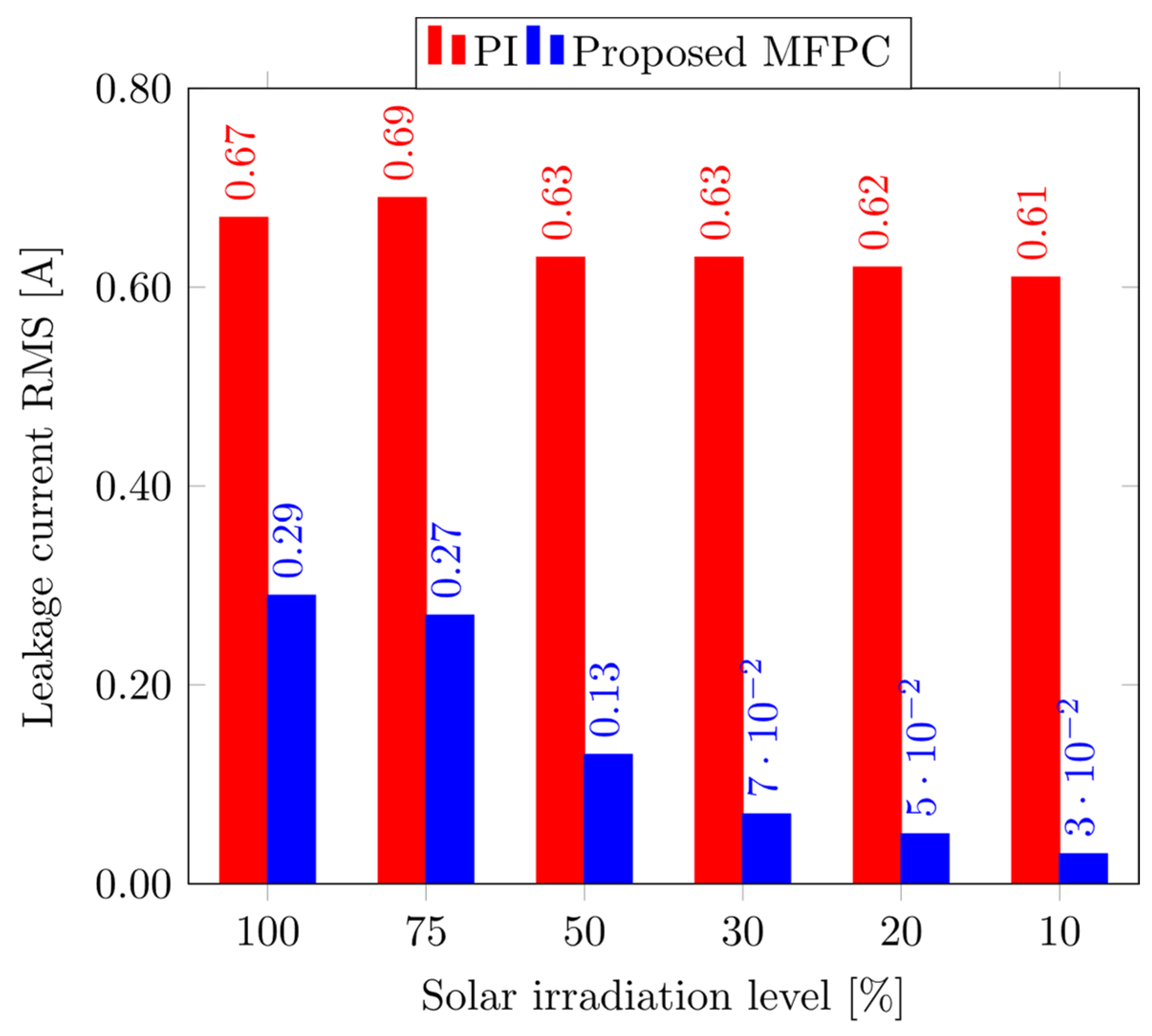
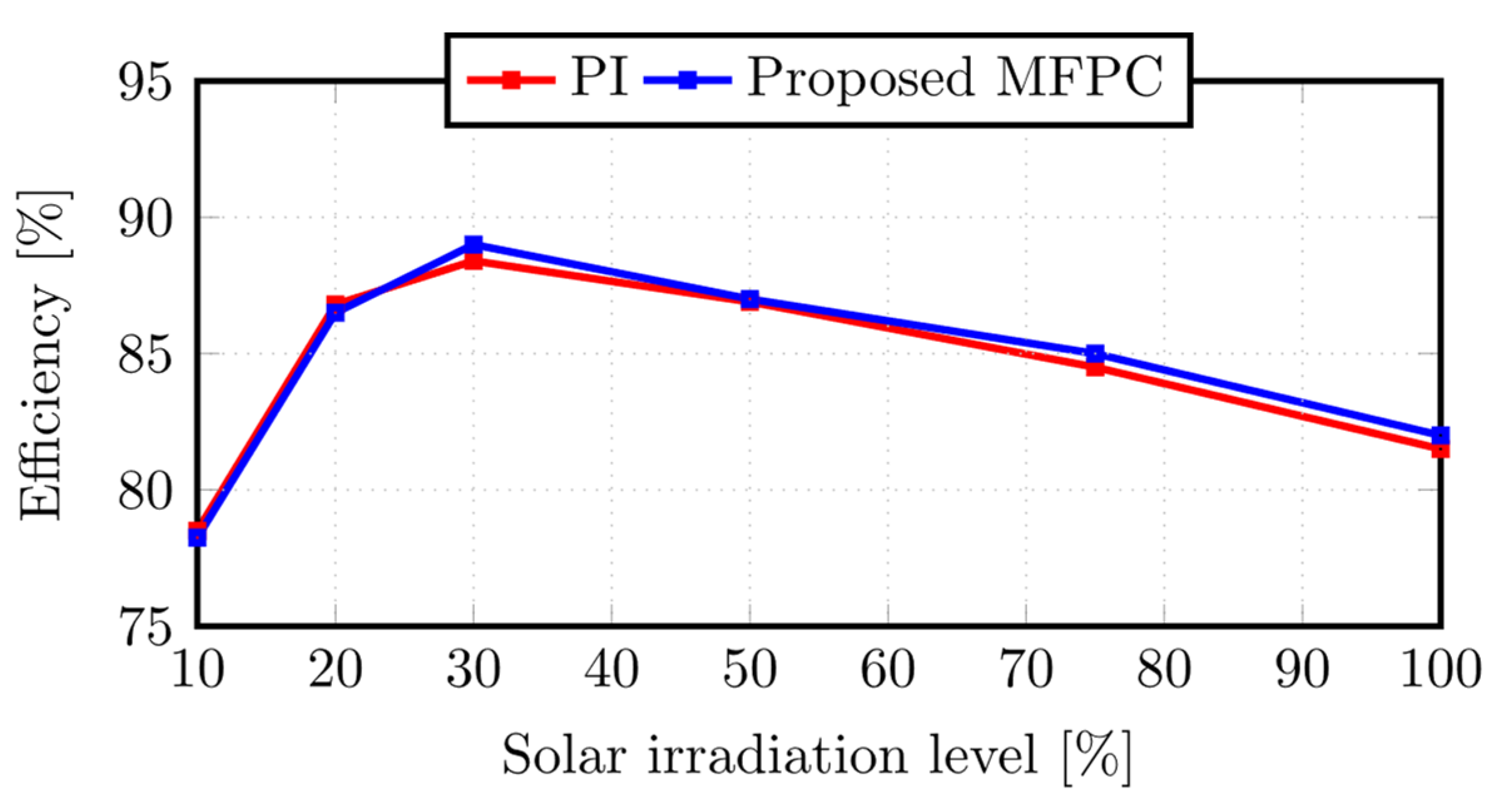
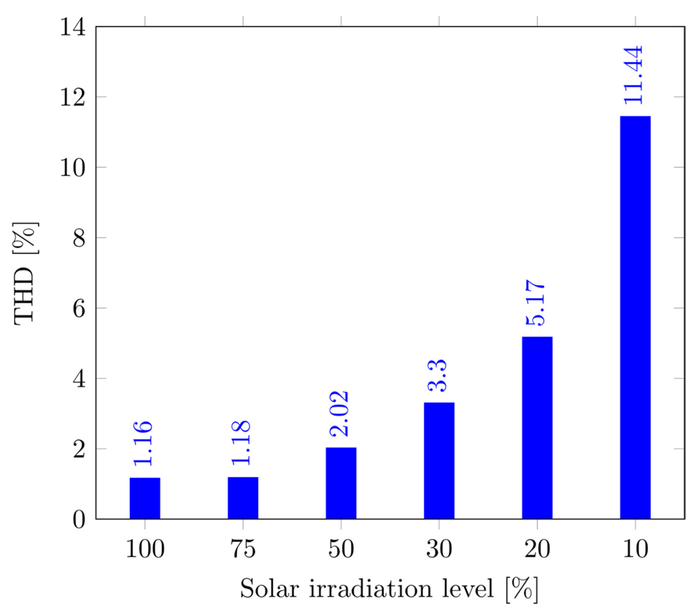
  • Explain how the MFPC affects performance variables such as the ground leaking current, grid current THD, and efficiency.
  • Evaluate the effectiveness of the systems that used the PI and MFPC controllers.
The paper is presented as follows. The studied system is explained in Section 2. The proposed MFPC controller design and the controllers for the entire system are covered in Section 3. A thorough explanation of the simulation findings is provided in Section 4. Finally, the paper’s overall conclusions are presented in Section 5.

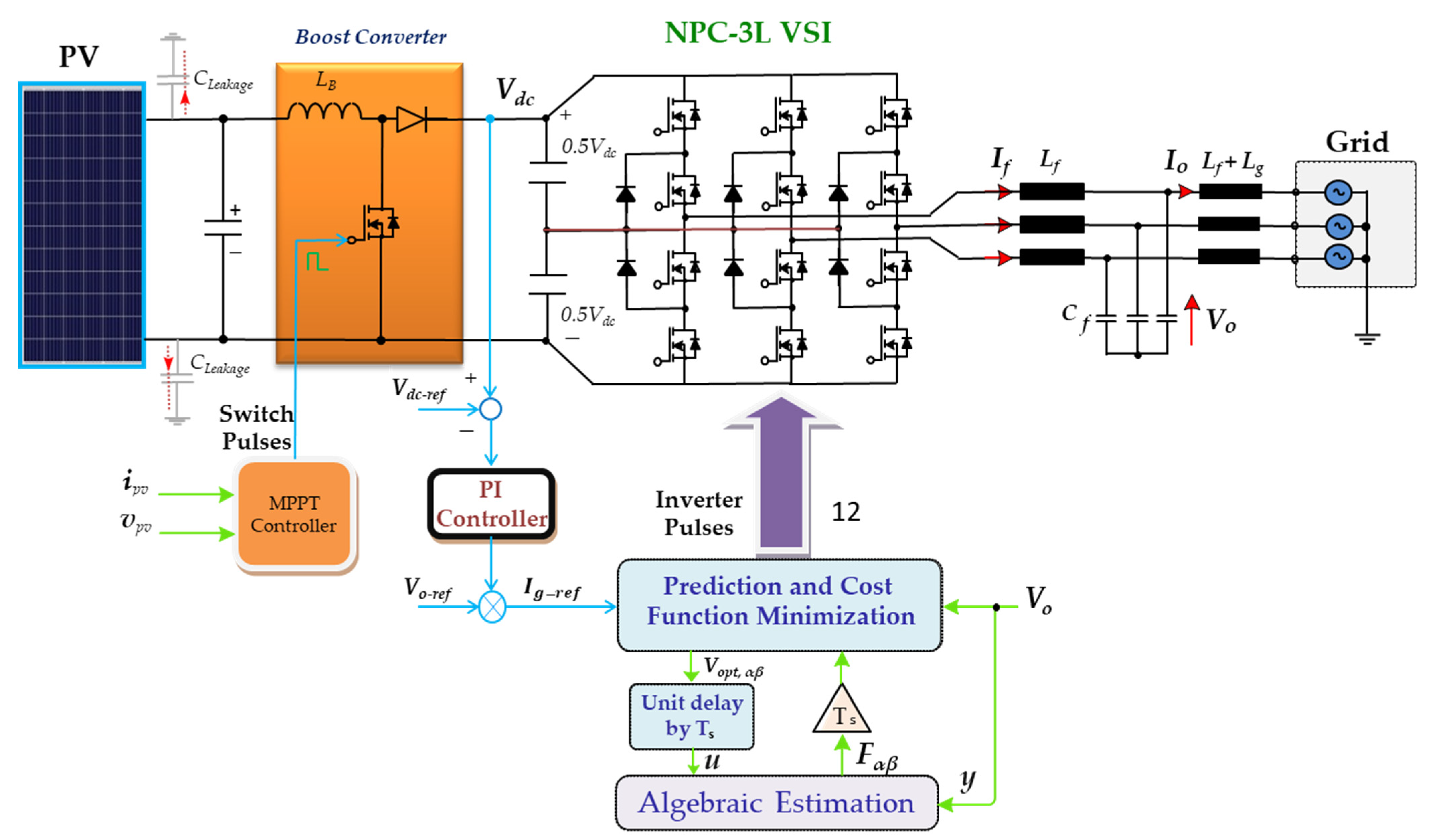
2. Configuration and Dynamic Modeling of the Proposed Energy System

The suggested device is a three-transformerless inverter supplied by solar energy and connected to the grid, as depicted in Figure 1. The PV screen, which is typically connected to a capacitor at its terminals, is the first step in the system. The power is regulated by the capacitor function, which also enhances solar efficiency [3]. The output of the photovoltaic system is then connected to a boost converter. For the photovoltaic panels, the boost converter serves as a changeable load. As a result, the PV’s MPPT (maximum power point tracking) function can be achieved by controlling the boost converter.
Additionally, the boost converter can scale up the solar voltage at low irradiation levels, therefore encouraging the drawing of modest amounts of electricity from solar. The DC link, connected to the input of the 3-φ transformerless inverter, is represented by the end of the boost converter’s output. The NPC architecture of the 3-φ transformerless converter. At the utility grid-connected inverter output ports, an LCL filter is installed. The filter reduces current behavior and prevents high-frequency waves [3]. One significant problem that has a significant impact on grid-connected inverters is the power grid’s weakness. The grid-connected converters should be attached to power systems with a short circuit ratio (SCR) > 20, which equates to a grid impedance of 5%, as suggested in the dispersed generation system guidelines [30]. When the SCR is maintained within the predetermined range, the grid-tied converters function steadily with the power system. Our research, therefore, made the assumption that the grid is a strong one. The following paragraph will describe each system component’s paradigm and method of operation.
Figure 1 depicts the NPC three-level inverter’s power circuit. It has six clamp diodes and twelve IGBTs. As the figure shows, two capacitors must divide the DC network voltage. The NPC three-level inverter has 27 switching states, as shown in Figure 2. These switching conditions result in 19 voltage vectors (V1,… V19) when they are depicted as space vectors. These vectors produce different common mode voltages, as indicated in [17]. However, seven states had zero common-mode voltage (V0, V8, V10, V12, V14, V16, V18).
According to the techniques utilized to minimize the earth leakage current in transformerless inverters, the common mode voltage should be kept minimum [30]. The NPC three-level inverter’s common mode voltage will be limited by using the prior seven switching states. The ground leakage current can be minimized as a result. The model takes into account the source inductance (Lg). The grid is assumed to be an endless 3-φ with a constant voltage magnitude and frequency. All of the three-phase quantities are represented as space vectors by:
U _ = 2 u a + e j 2 π / 3 u b + e j 4 π / 3 u c / 3
where U is the space vector, and (ua, ub, and uc) are the 3-φ quantities.
The fundamental principles of the circuit can be used to describe the system’s dynamic behavior, as follows:
L g f d I ¯ g d t L f d I ¯ i n v d t C f d V ¯ C d t = V ¯ c V ¯ g V ¯ i n v V ¯ c I ¯ f I ¯ g ,   L g f = L g + L f ,  
where (Cf) is the filter capacitance, (rf, Lf) are the filter inductor parameters, (Rg, Lg) is the grid impedance, ( V ¯ i n v ) is the inverter space vector voltage, ( I ¯ i n v ) is the inverter current space vector, ( V ¯ f ) is the filter capacitor space voltage vector, and ( I ¯ g ,   V ¯ g ) are the grid current and voltage space vectors, respectively.
The state-space matrix structure can be used to rewrite Equation (2), as follows:
d d t I ¯ g I ¯ i n v V ¯ f = R g + r f L g f 0 1 L g f 0 r f L f 1 L f 1 C f 1 C f 0 I ¯ g I ¯ i n v V ¯ f + 0 1 L f 0 V ¯ i n v + 1 L g 0 0 V ¯ g .
This can be stated simply as:
d Y ¯ d t = α Y ¯ + β V ¯ i n v + γ V ¯ g ,
where the constant matrices (α, β, and γ) and the state vector ( Y ¯ ) are given by:
Y ¯ = I ¯ g I ¯ i n v V ¯ f ,   α = R g + r f L g f 0 1 L g f 0 r f L f 1 L f 1 C f 1 C f 0 , β = 0 1 L f 0 , γ = 1 L g 0 0 .
Predicting the future values of the controlled variables is necessary for implementing the traditional MPC method. The system discrete model is used to carry out the forecast procedure. Typically, the forward Euler estimate is used to find this model:
d X _ d t = X _ k + 1 X _ k T s
Equation (6) allows the state space equation in (4) to be discretized as follows, where Ts is the sampling time:
Y ¯ k + 1 = e α T Y ¯ k + 0 T e α τ β d τ V ¯ i n v + 0 T e α τ γ d τ V ¯ g .
These formulas can be used to forecast the system variables for the subsequent sample. The system is then guided to the designated point using an optimization method that has been modified. The cost function will be used in this procedure.

3. Proposed System Control

There are three controllers to control the proposed PV grid-tied system. Each controller is designed to represent a different part of the system. The first controller is the MPPT controller, which adjusts the PV operating point to match the MPPT conditions as closely as possible by controlling the duty cycle of the interfaced boost converter. The second controller regulates the voltage on the DC link by generating the reference grid current. Finally, the third controller regulates the grid current of the 3L-NPC transformerless inverter controller. The three control schemes are studied in detail in the following subsections.

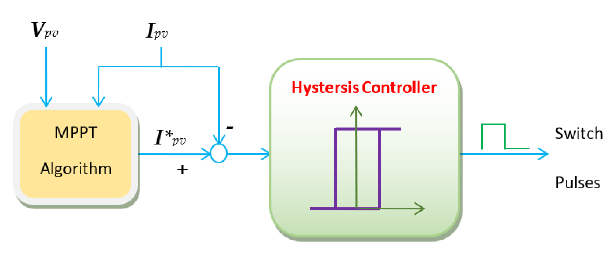
3.1. Maximum Power Point Tracking (MPPT)

Extracting the maximum power from a PV system is essential for optimizing its use, so operating it at the maximum power point (MPP) condition is necessary [31,32,33,34,35,36,37]. The MPPT algorithm based on incremental conductance (INC) is employed to utilize the maximum permissible PV power. The INC has better tracking of the peak power of a solar panel and improved dynamic performance in rapidly changing conditions [38]. It starts by observing the power change (ΔP) and voltage change (ΔV) over time. When the change in power or voltage reaches zero, this indicates that the MPP is achieved, according to [39]:
Δ P Δ V < 0             o n   t h e   r i g h t   s i d e   o f   t h e   M P P T   c o n d i t i o n   a t   t h e   c u r v e Δ P Δ V = 0                                                                                                                                     a t   t h e   M P P T   c o n d i t i o n Δ P Δ V > 0                   o n   t h e   l e f t   s i d e   o f   t h e   M P P T   c o n d i t i o n   a t   t h e   c u r v e
The MPPT algorithm will set the reference current of the current-regulated boost converter, which will keep the MPPT conditions in place, as shown in Figure 3. Next, the hysteresis controller can regulate the PV current to its reference value from the MPPT by generating an ON/OFF state for the boost converter switch.

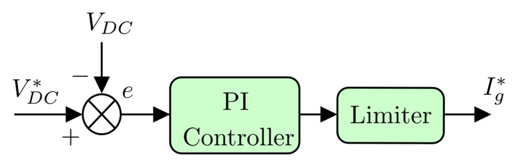
3.2. Voltage Controller of the DC Link

This controller helps keep the voltage on the DC link stable at a predefined setpoint ( V D C ) so the system can work properly. It controls the power flow from the PV side to the grid side by generating the reference RMS value of the grid current I g , as shown in Figure 4. This controller needs to be able to work with a lower bandwidth than the inverter controller to preserve system stability. The controller will use the proportional–integral regulator to maintain the setpoint. There is no need for a complex control strategy since the setpoint is fixed. It generates the reference grid’s current value. In this paper, the Ziegler–Nichols method is used to tune the gains of a DC link PI controller. This method is effective in adjusting the controller to achieve the desired performance.

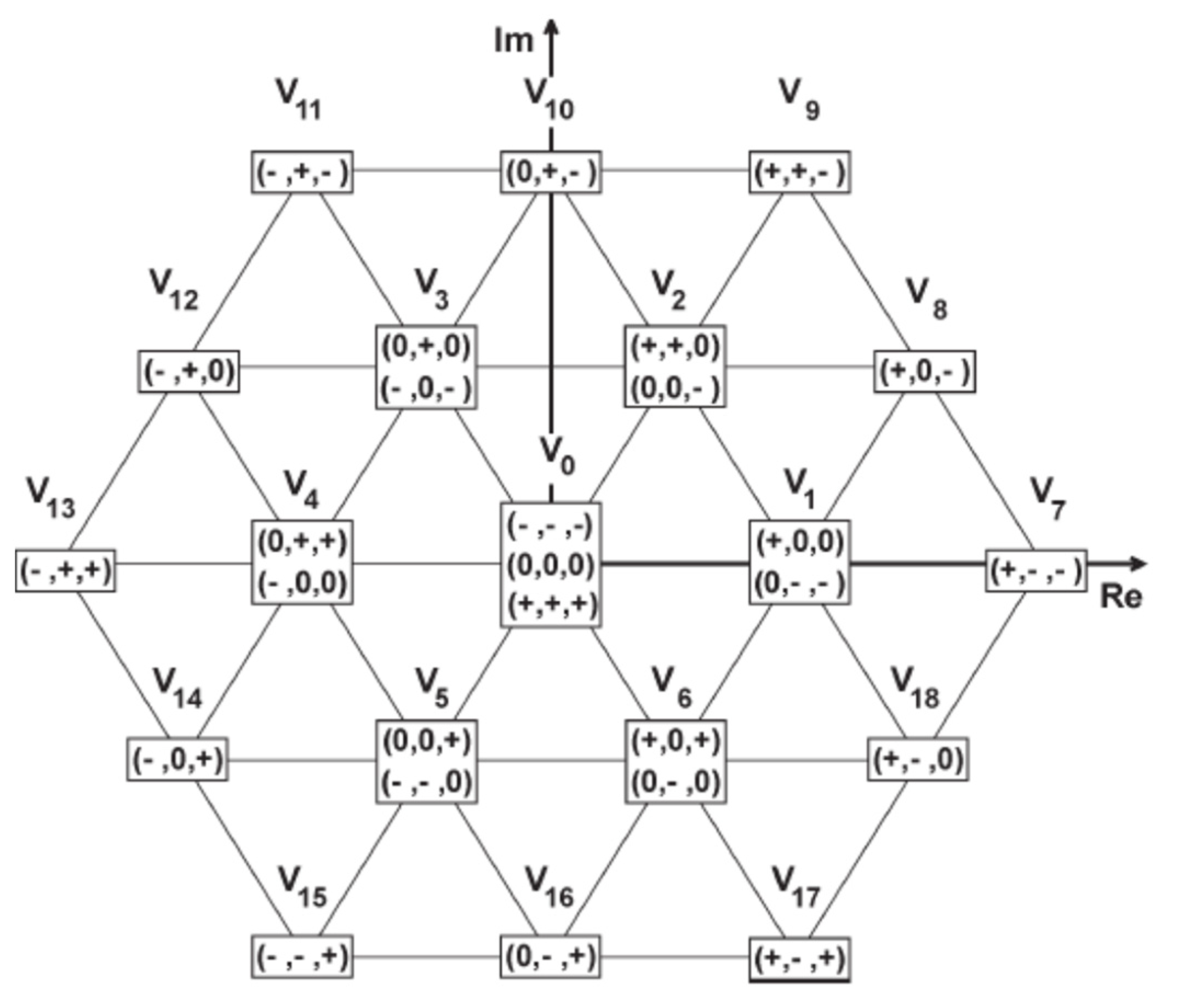
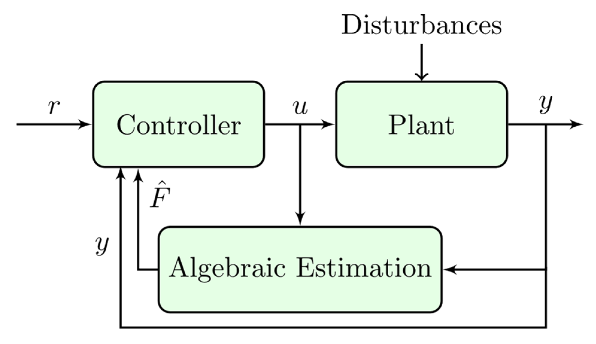
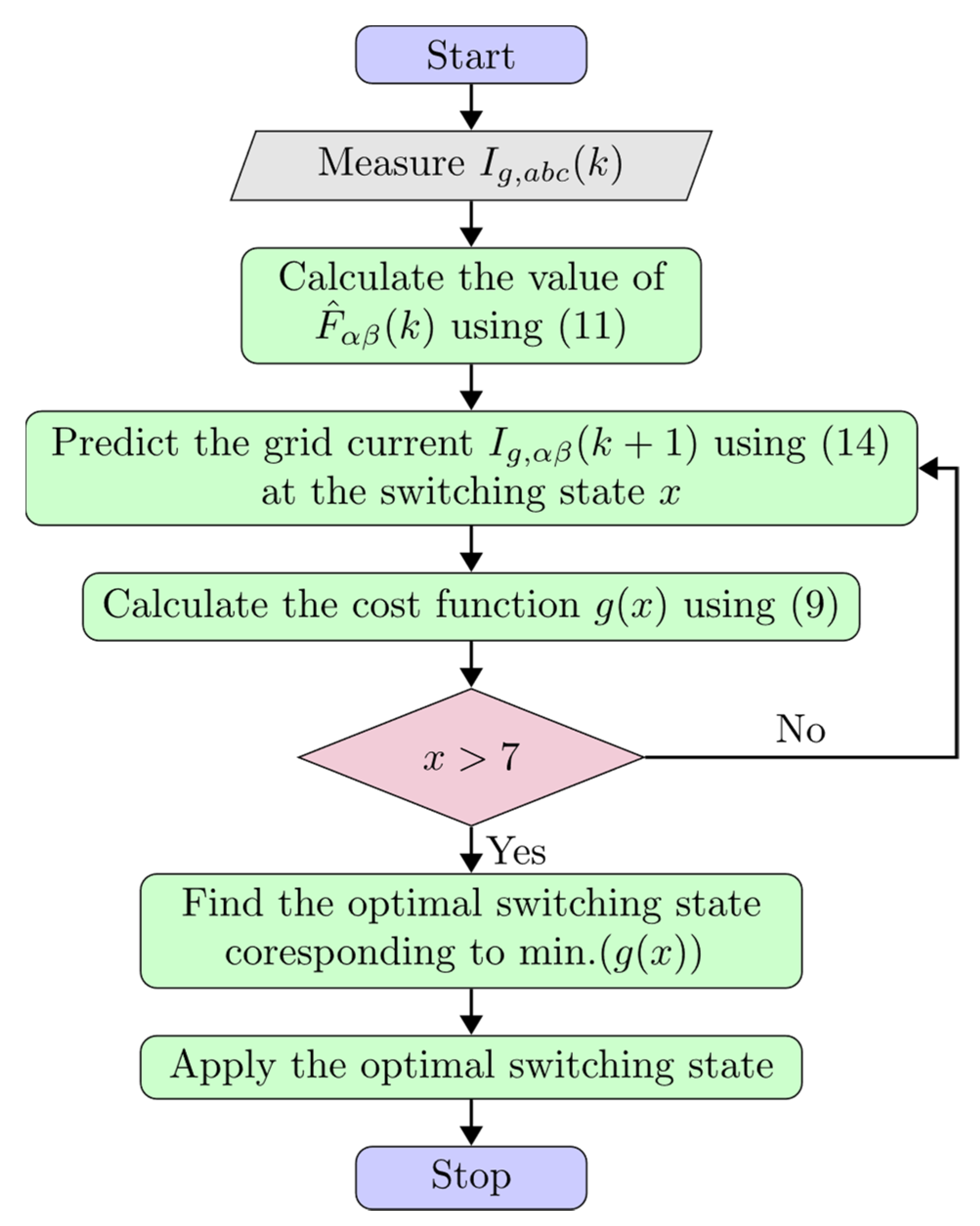
3.3. Proposed Model-Free Predictive Control for 3L-NPC

The 3L-NPC voltage source inverter has four switches and two diodes per leg, and there are three allowable switching states [−1, 0, and 1] per phase. Suppose the voltage across each capacitor is assumed to be half of the DC link voltage. In that case, the generated output voltage has the following values: [−VDC/2, 0, VDC/2]. Therefore, it has 3^3 = 27 switching states for the three-phase. To reduce the amount of leakage current in the system due to the PV capacitance, seven potential voltage vectors are used to predict the grid current [39]. These seven states have low common mode voltage (CMV). The value of the controlled variables will be predicted at each possible switching state.
The conventional MPC scheme relies on predicting future manipulated variables using discrete modeling. The MFPC approach differs from this in that it does not depend on predicting these variables using their discrete modeling. Instead, it uses a continuous modeling approach that considers past data to predict future outcomes using the ultra-local model (ULM). The MFPC approach relies on modeling the change in system parameters as a disturbance. This allows us to understand and predict how the system will respond. This way, model-free predictive control makes the controlled variables’ prediction behavior more accurate and efficient. An optimal switching state must be selected to make the grid current as close to its target value as possible for each sampling period. This controller is designed to keep the grid current vector (Ig) aligned with a sinusoidal reference and achieve a unity power factor. It does this by adjusting the current according to a sinusoidal reference signal.
The grid current has a sinusoidal shape and is considered a balanced waveform. Then, the value of the grid current’s real and imaginary parts (αβ) can be evaluated at every switching state. The cost function is then calculated in each switching state. It contains the squared error between the predicted grid current and the reference current in the αβ frame, as in (14). This cost function is the core of the optimization process in predictive control. The employed cost function here does not use any weighting factors, as it has two terms with the same physical quantity and the same property as well. To simplify its design, no constraints are involved in the cost function. The switching state corresponding to the minimum cost function will be applied to derive the inverter switches in the next sampling time. The considered utility grid is a type of electrical grid that is reliable and has a constant frequency. This means that the voltage across the point of connection will remain the same.
J = I g , α β k + 1 I g , α β 2
where I g , α β k + 1 are the predicted real and imaginary grid currents at an instant (k + 1) in (αβ) coordination frame, and I g , α β are the real and imaginary components of the grid current reference.
This paper explains a new way to control the transformerless PV grid-tied system without knowing the system’s specific parameters. This data-driven approach is called model-free predictive control (MFPC). Figure 5 shows the general fundamental building blocks of an ultralocal model, which is the basis for MFPC. The variable F represents the overall uncertainty and disruption of the system, also known as the unknown function [40]. The system’s output and input data are required to find the value of the unknown function F’s value. In addition, the principle of the ULM can be formulated as follows:
y n = F + α u
where y n represents the nth derivative of y, u denotes the input of the controlled plant, y refers to the plant output, and α ∈ R stands for the non-physical parameter. The order n, in most cases, is selected by the practitioner as either 1 or 2, with 1 being the option chosen the most often in all actual circumstances [41].
The algebraic identification approaches can help to determine the estimated value of the unknown function F. The value of F can be substituted with a more exact number in place of the estimate by using the letter F ^ . Finally, the Heun technique [40,41] can be applied to estimate the value of F ^ as follows:
F ^ = 3 N f 3 T s i = 1 N f F 1 + F 2
where
F 1 = N f 2 i 1 y k 1 + N f 2 i y k F 2 = α i 1 T s N f i 1 u k 1 + α i T s N f i u k  
where Nf is the window length and Ts is the sampling period.
The derivative of the grid current, which is the controlled variable in the current study, according to the ULM concept, can be formulated as:
d I g , α β d t = F ^ α β + α u α β  
The MFPC model can predict the value of the grid current at different possible Vx,αβ voltage vectors. Next, the Euler theory can help solve the differential term in the equation, which enables the prediction of the output voltage for any given voltage vector, as below:
I g , α β k + 1 = I g , α β k + T s F ^ α β + α V x , α β
where I g , α β k is the measured grid current at instant k and V x , α β is the voltage vector. The configuration of the proposed MFPC for transformerless PV grid-tied applications is sketched in Figure 6.
A complete flowchart of the proposed MFPC for the three-phase NPC is depicted in Figure 7. The MFPC first considers the necessary measurements to predict the desired control objectives. To improve accuracy, these measurements are filtered from the noise. Next, the best switching state is selected according to the minimum cost function.

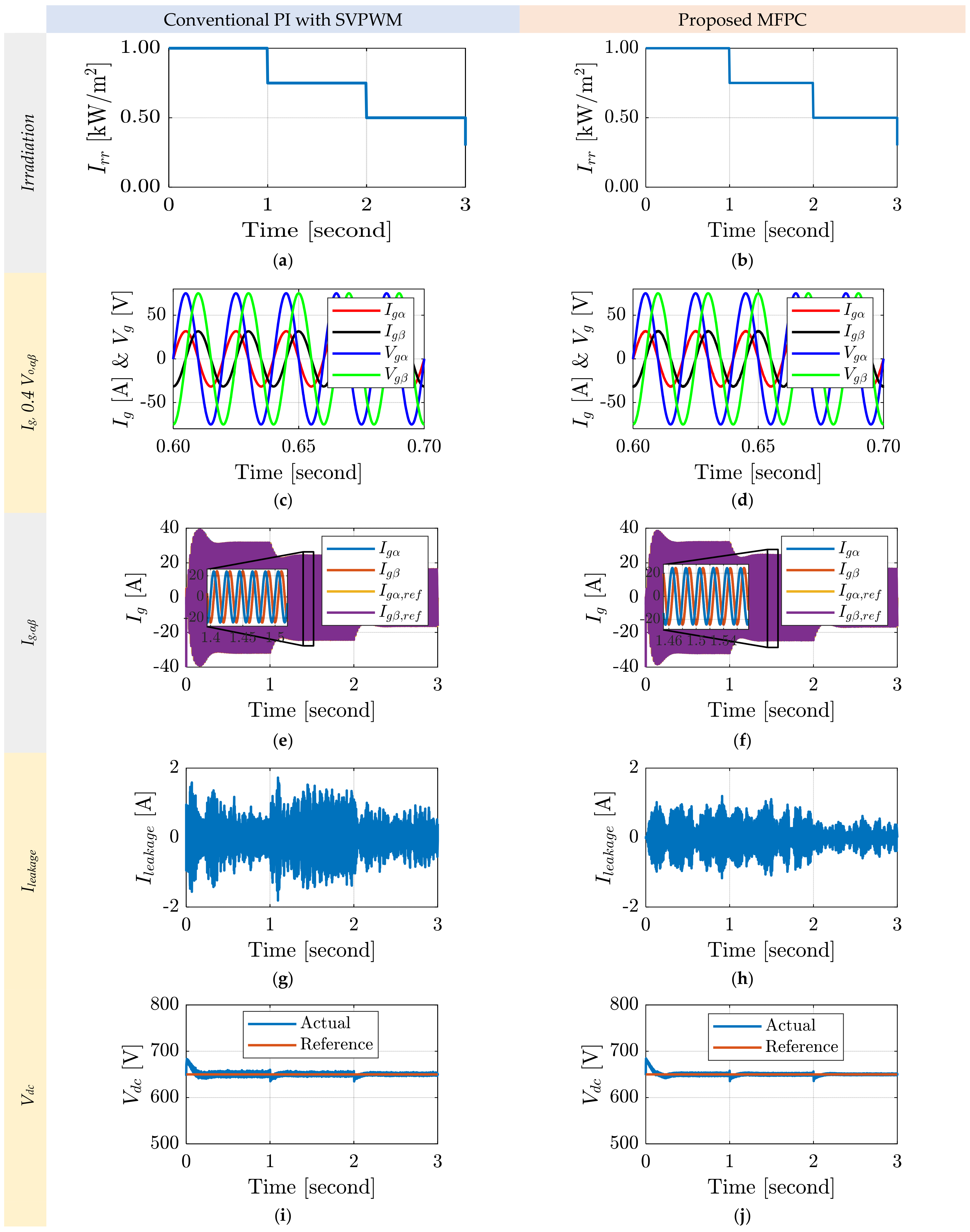
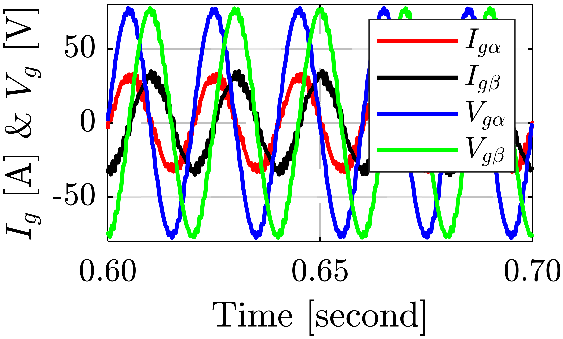
4. Results and Discussion

The MATLAB/Simulink platform was used to model the suggested system depicted in Figure 1. Table 1 contains a summary of the system settings and specifications.
The findings of the suggested NPC transformerless inverter controlled by the MFPC controller and the PI current controller with SVPWM modulation are compared in Figure 8. The disturbance of the proposed system is the irradiation level that has been assumed of step variation, as shown in Figure 8a,b. With the two regulators, the three-phase grid currents have a power factor of one and are sinusoidally in phase with the grid voltage, as presented in Figure 8c,d. Figure 8e,f shows the grid current variations during the step irradiation variations. In both cases, the grid current tracks the reference currents generated by the current controllers. It is noted that the peak grid current drops as the irradiation level drops; hence, the grid power is proportional to that generated by the PV. Current overshoots are present at the instants of step disturbance. However, the grid current overshoots with the MFPC controller are smaller than those with the PI current controller by about 10%. The earth leakage current responses with the two controllers are illustrated in Figure 8g,h. It is abundantly obvious from the earth leakage current that the MPC controller box is significantly smaller than the PI controller by about 37.5%. Figure 8i,j displays the DC link voltage values for the two control methods. The MFPC controller case reduces the voltage ripples by almost 2%. One cause of distortion in the transformerless inverter could be these fluctuations.
Figure 9 displays the grid current’s FFT spectrum at 100% solar illumination. The data show that the lower order frequencies in the MFPC case are lower than those in the PI case. It is evident that the harmonics’ number for the PI instance is the lowest. The MFPC control policy’s training and refining procedures reduce the THD of the grid current. As a result, in the case of MFPC, the THD of the grid current is smaller than in the case of PI. With the MFPC management scheme, the grid current’s THD is 1.16%, whereas with the PI scheme, it is 1.69%. The two methods have low-order overtones in the grid current spectrum. This demonstrates how much better the suggested MFPC strategy is. The grid current in the (αβ) coordinates in the case of the weak grid is shown in Figure 10. The resistance of the weak grid is 0.0748 Ω, while the grid inductance equals 0.238 mH. A unity power factor is achieved with the proposed MFPC.
Figure 11 shows the relationship between the solar radiation intensity and the RMS of the leaking current for both controllers. It is clear that the MFPC controller reduces the leakage current number at all irradiation levels. The average reduction in the RMS of the leaking current is 62.5%. The distribution of the power losses is provided in Figure 12. It is clear that most of the power loss is dissipated in the resistance of the LCL filter.
Figure 13 depicts how the efficiency of the MFPC and PI controllers varies with the irradiation intensity. The MPC controller has higher efficiency than the PI controller at most irradiation values. Because the two instances use the same hardware, but distinct processors, the inverter switching pattern and harmonics vary. These variations resulted from the MPC controller’s superior switching patterns and reduced overtones compared to other controllers. Therefore, the MPC controller’s low harmonic and tiny switching losses account for its greater efficiency.
The change of the grid current THD with the irradiation level is shown in Figure 14. Although the grid current THD has excellent performance for high insolation levels, the THD for low insolation levels <20% is higher than the standards. This is one of the limitations of this system and will be a future research point. Therefore, the current error minimization procedure that takes place when the MFPC controller is applied may be utilized to describe the outcome in this paper.

5. Conclusions

This paper suggested using an NPC transformerless inverter that is grid-tied and powered by solar energy. An LCL filter connects the transformerless converter to the power. The system model takes into account the filter components as well as the grid’s internal resistance. The suggested system’s discrete model is established before the MFPC controller’s method is described. The suggested system is simulated in MATLAB using the MFPC and a standard PI current controller with SVPWM modulation. According to the simulation findings, the MPC controller has the greatest efficiency across all of the comparison variables. With the two regulators, the 3-φ voltages and grid currents are pure sinusoidal and in phase with the grid voltage or unity power factor. However, the grid current THD is reduced with the MFPC controller lower than the PI controller by about 31%. However, the leakage current in the MFPC scenario is only about 62.5% of that in the PI controller situation. Additionally, compared to a system that uses a PI current controller with SVPWM modulation, the system that employs MFPC is more efficient. The future work in this area could be directed toward identifying the unknown function value of F in the proposed MFPC using the state observers. This could improve the accuracy of the tracking system. In addition, future work will focus on investigating how to implement the proposed system.

Author Contributions

S.A.Z. designed and conceived the system, analyzed the results, and derived the model. A.B. designed the controller. H.A. (Hani Albalawi) and A.M.A. helped to write and proofread the manuscript. In addition, H.A. (Hassan Abdeldaim) and B.M. receiving the funding. All authors have read and agreed to the published version of the manuscript.

Funding

The University of Tabuk provided funding for this study under Grant Number S-1442-0132, which can be found at https://www.ut.edu.sa/web/deanship-of-scientific-research/home, (accessed date on 15 February 2023).

Data Availability Statement

Not applicable.

Acknowledgments

The Deanship of Scientific Research at the University of Tabuk received financing for this work under research number S-1442-0132, which is acknowledged by the authors.

Conflicts of Interest

The authors declare no conflict of interest.

References

  1. Kerekes, T.; Teodorescu, R.; Liserre, M.; Klumpner, C.; Sumner, M. Evaluation of three-phase transformerless photovoltaic inverter topologies. IEEE Trans. Power Electron. 2009, 24, 2202–2211. [Google Scholar] [CrossRef]
  2. Albalawi, H.; Zaid, S.A. Performance Improvement of a Grid-Tied Neutral-Point-Clamped 3-φ Transformerless Inverter Using Model Predictive Control. Processes 2019, 7, 856. [Google Scholar] [CrossRef] [Green Version]
  3. Zaid, S.A.; Kassem, A.M. Review, analysis and improving the utilization factor of a PV-grid connected system via HERIC transformerless approach. Renew. Sustain. Energy Rev. 2017, 73, 1061–1069. [Google Scholar] [CrossRef]
  4. Cavalcanti, M.C.; Farias, A.M.; Oliveira, K.C.; Neves, F.A.S.; Afonso, J.L. Eliminating Leakage Currents in Neutral Point Clamped Inverters for Photovoltaic Systems. IEEE Trans. Ind. Electron. 2011, 59, 435–443. [Google Scholar] [CrossRef]
  5. Gonzalez, R.; Lopez, J.; Sanchis, P.; Marroyo, L. Transformerless Inverter for Single-Phase Photovoltaic Systems. IEEE Trans. Power Electron. 2007, 22, 693–697. [Google Scholar] [CrossRef]
  6. Xiao, H.; Xie, S.; Chen, Y.; Huang, R. An Optimized Transformerless Photovoltaic Grid-Connected Inverter. IEEE Trans. Ind. Electron. 2010, 58, 1887–1895. [Google Scholar] [CrossRef]
  7. Kerekes, T.; Teodorescu, R.; Rodriguez, P.; Vazquez, G.; Aldabas, E. A New High-Efficiency Single-Phase Transformerless PV Inverter Topology. IEEE Trans. Ind. Electron. 2009, 58, 184–1911. [Google Scholar] [CrossRef] [Green Version]
  8. Freddy, T.K.S.; Rahim, N.A.; Hew, W.-P.; Che, H.S. Comparison and Analysis of Single-Phase Transformerless Grid-Connected PV Inverters. IEEE Trans. Power Electron. 2013, 29, 5358–5369. [Google Scholar] [CrossRef]
  9. Cavalcanti, M.C.; De Oliveira, K.C.; Neves, F.A.S.; Azevedo, G.M.S.; Camboim, F.C. Modulation Techniques to Eliminate Leakage Currents in Transformerless Three-Phase Photovoltaic Systems. IEEE Trans. Ind. Electron. 2009, 57, 1360–1368. [Google Scholar] [CrossRef]
  10. Gupta, A.K.; Agrawal, H.; Agarwal, V. A Novel Three-Phase Transformerless H-8 Topology with Reduced Leakage Current for Grid-Tied Solar PV Applications. IEEE Trans. Ind. Appl. 2018, 55, 1765–1774. [Google Scholar] [CrossRef]
  11. Bradaschia, F.; Cavalcanti, M.C.; Ferraz, P.E.P.; Neves, F.A.S.; Dos Santos, E.C.; Da Silva, J.H.G.M. Modulation for Three-Phase Transformerless Z-Source Inverter to Reduce Leakage Currents in Photovoltaic Systems. IEEE Trans. Ind. Electron. 2011, 58, 5385–5395. [Google Scholar] [CrossRef]
  12. Guo, X. Three-Phase CH7 Inverter with a New Space Vector Modulation to Reduce Leakage Current for Transformerless Photovoltaic Systems. IEEE J. Emerg. Sel. Top. Power Electron. 2017, 5, 708–712. [Google Scholar] [CrossRef]
  13. Guo, X.; Zhang, X.; Guan, H.; Kerekes, T.; Blaabjerg, F. Three-Phase ZVR Topology and Modulation Strategy for Transformerless PV System. IEEE Trans. Power Electron. 2018, 34, 1017–1021. [Google Scholar] [CrossRef] [Green Version]
  14. Freddy, T.K.S.; Rahim, N.A.; Hew, W.-P.; Che, H.S. Modulation Techniques to Reduce Leakage Current in Three-Phase Transformerless H7 Photovoltaic Inverter. IEEE Trans. Ind. Electron. 2014, 62, 322–331. [Google Scholar] [CrossRef]
  15. Krishna, R.A.; Suresh, L.P. A brief review on multi level inverter topologies. In Proceedings of the International Conference on Circuit, Power and Computing Technologies (ICCPCT), Nagercoil, India, 18–19 March 2016; pp. 1–6. [Google Scholar] [CrossRef]
  16. Akbari, A.; Poloei, F.; Bakhshai, A. A Brief Review on State-of-the-art Grid-connected Inverters for Photovoltaic Applications. In Proceedings of the IEEE 28th International Symposium on Industrial Electronics (ISIE), Vancouver, BC, Canada, 12–14 June 2019; pp. 1023–1028. [Google Scholar] [CrossRef]
  17. Zhang, H.; Jouanne, A.V.; Dai, S.; Wallace, A.K.; Wang, F. Multilevel inverter modulation schemes to eliminate common-mode voltages. IEEE Trans. Ind. Appl. 2000, 36, 1645–1653. [Google Scholar] [CrossRef]
  18. Alepuz, S.; Busquets-Monge, S.; Bordonau, J.; Gago, J.; Gonzalez, D.; Balcells, J. Interfacing Renewable Energy Sources to the Utility Grid Using a Three-Level Inverter. IEEE Trans. Ind. Electron. 2006, 53, 1504–1511. [Google Scholar] [CrossRef]
  19. Bakeer, A.; Ismeil, M.A.; Kouzou, A.; Orabi, M. Development of MPC algorithm for quasi Z-source inverter (qZSI). In Proceedings of the 2015 3rd International Conference on Control, Engineering & Information Technology (CEIT), Tlemcen, Algeria, 25–27 May 2015; pp. 1–6. [Google Scholar] [CrossRef]
  20. Bakeer, A.; Magdy, G.; Chub, A.; Vinnikov, D. Predictive control based on ranking multi-objective optimization approaches for a quasi-Z source inverter. CSEE J. Power Energy Syst. 2021, 7, 1152–1160. [Google Scholar] [CrossRef]
  21. Stenman, A. Model-free predictive control. In Proceedings of the 38th IEEE Conference Decisision Control, Phoenix, AZ, USA, 7—10 December 1999; Volume 4, pp. 3712–3717. [Google Scholar]
  22. Rodriguez, J.; Heydari, R.; Rafiee, Z.; Young, H.A.; Flores-Bahamonde, F.; Shahparasti, M. Model-Free Predictive Current Control of a Voltage Source Inverter. IEEE Access 2020, 8, 211104–211114. [Google Scholar] [CrossRef]
  23. Zhang, Y.; Liu, X.; Liu, J.; Rodriguez, J.; Garcia, C. Model-free predictive current control of power converters based on ultra-local model. In Proceedings of the 2020 IEEE International Conference on Industrial Technology (ICIT), Buenos Aires, Argentina, 26–28 February 2020; pp. 1089–1093. [Google Scholar]
  24. Khalilzadeh, M.; Vaez-Zadeh, S.; Rodriguez, J.; Heydari, R. Model-Free Predictive Control of Motor Drives and Power Converters: A Review. IEEE Access 2021, 9, 105733–105747. [Google Scholar] [CrossRef]
  25. Wang, S.; Li, J.; Hou, Z.; Meng, Q.; Li, M. Composite Model-free Adaptive Predictive Control for Wind Power Generation Based on Full Wind Speed. CSEE J. Power Energy Syst. 2022, 8, 1659–1669. [Google Scholar] [CrossRef]
  26. Chen, H.; Chen, J.; Lu, H.; Yan, C.; Liu, Z. A Modified MPC-Based Optimal Strategy of Power Management for Fuel Cell Hybrid Vehicles. IEEE/ASME Trans. Mechatron. 2020, 25, 2009–2018. [Google Scholar] [CrossRef]
  27. Xia, C.; Wang, M.; Song, Z.; Liu, T. Robust Model Predictive Current Control of Three-Phase Voltage Source PWM Rectifier with Online Disturbance Observation. IEEE Trans. Ind. Inform. 2012, 8, 459–471. [Google Scholar] [CrossRef]
  28. Zhang, Y.; Liu, J. An improved model-free predictive current control of pwm rectifiers. In Proceedings of the 2017 20th International Conference on Electrical Machines and Systems (ICEMS), Sydney, NSW, Australia, 11–14 August 2017; pp. 1–5. [Google Scholar]
  29. Fliess, M.; Join, C. Model-free control and intelligent pid controllers: Towards a possible trivialization of nonlinear control? IFAC Proc. Vol. 2009, 42, 1531–1550. [Google Scholar] [CrossRef] [Green Version]
  30. Zaid, S.A.; Albalawi, H.; AbdelMeguid, H.; Alhmiedat, T.A.; Bakeer, A. Performance Improvement of H8 Transformerless Grid-Tied Inverter Using Model Predictive Control Considering a Weak Grid. Processes 2022, 10, 1243. [Google Scholar] [CrossRef]
  31. Pendem, S.R.; Mikkili, S. Assessment of Cross-coupling Effects in PV String-integrated-converters with P&O MPPT Algorithm Under Various Partial Shading Patterns. CSEE J. Power Energy Syst. 2022, 8, 1013–1028. [Google Scholar] [CrossRef]
  32. Pan, Y.; Sangwongwanich, A.; Yang, Y.; Blaabjerg, F. A Phase-Shifting MPPT to Mitigate Interharmonics from Cascaded H-Bridge PV Inverters. IEEE Trans. Ind. Appl. 2021, 57, 3052–3063. [Google Scholar] [CrossRef]
  33. Ghaderi, D. An FPGA-based switching photovoltaic-connected inverter topology for leakage current suppression in grid-connected utilizations. Int. J. Circuit Theory Appl. 2020, 48, 1724–1743. [Google Scholar] [CrossRef]
  34. Kumar, V.; Singh, M. Derated Mode of Power Generation in PV System Using Modified Perturb and Observe MPPT Algorithm. J. Mod. Power Syst. Clean Energy 2021, 9, 1183–1192. [Google Scholar] [CrossRef]
  35. Pendem, S.R.; Mikkili, S.; Bonthagorla, P.K. PV Distributed-MPP Tracking: Total-Cross-Tied Configuration of String-Integrated-Converters to Extract the Maximum Power Under Various PSCs. IEEE Syst. J. 2020, 14, 1046–1057. [Google Scholar] [CrossRef]
  36. Ko, Y.; Andresen, M.; Wang, K.; Liserre, M.G. Modulation for Cascaded Multilevel Converters in PV Applications with High Input Power Imbalance. IEEE Trans. Power Electron. 2021, 36, 10866–10878. [Google Scholar] [CrossRef]
  37. Darwish, A.; Alotaibi, S.; Elgenedy, M.A. Current-Source Single-Phase Module Integrated Inverters for PV Grid-Connected Applications. IEEE Access 2020, 8, 53082–53096. [Google Scholar] [CrossRef]
  38. Bakeer, A.; Salama, H.; Vokony, I. Integration of PV system with SMES based on model predictive control for utility grid reliability improvement. Prot. Control. Mod. Power Syst. 2021, 6, 14. [Google Scholar] [CrossRef]
  39. Zaid, S.A.; Mohamed, I.S.; Bakeer, A.; Liu, L.; Albalawi, H.; Tawfiq, M.E.; Kassem, A.M. From MPC-Based to End-to-End (E2E) Learning-Based Control Policy for Grid-Tied 3L-NPC Transformerless Inverter. IEEE Access 2022, 10, 57309–57326. [Google Scholar] [CrossRef]
  40. Zaid, S.A.; Bakeer, A.; Magdy, G.; Albalawi, H.; Kassem, A.M.; El-Shimy, M.E.; AbdelMeguid, H.; Manqarah, B. A New Intelligent Fractional-Order Load Frequency Control for Interconnected Modern Power Systems with Virtual Inertia Control. Fractal Fract. 2023, 7, 62. [Google Scholar] [CrossRef]
  41. Bakeer, A.; Magdy, G.; Chub, A.; Jurado, F.; Rihan, M. Optimal Ultra-Local Model Control Integrated with Load Frequency Control of Renewable Energy Sources Based Microgrids. Energies 2022, 15, 9177. [Google Scholar] [CrossRef]
Figure 1. Proposed PV-powered NPC transformerless inverter with the MFPC.
Energies 16 03141 g001
Figure 2. Space vectors of NPC 3-φ inverter.
Energies 16 03141 g002
Figure 3. MPPT controller block diagram.
Energies 16 03141 g003
Figure 4. DC link capacitor voltage controller.
Energies 16 03141 g004
Figure 5. Basic implementation of the ULM.
Energies 16 03141 g005
Figure 6. Configuration of the MFPC for the grid current control.
Energies 16 03141 g006
Figure 7. Flowchart of the proposed MFPC for the grid current control.
Energies 16 03141 g007
Figure 8. Suggested NPC transformerless inverter’s grid voltage, grid current, irradiation, earth leakage current, and DC link voltage simulation findings for conventional SVPWM with PI current controller and MFPC controller.
Energies 16 03141 g008
Figure 9. Grid-current spectrum for the: (a) conventional PI current controller with SVPWM modulation, and (b) proposed MFPC controller (at 100% irradiation level).
Energies 16 03141 g009
Figure 10. Proposed NPC transformerless inverter’s grid current simulation findings for MFPC controller at weak grid condition (i.e., grid resistance = 0.0748 Ω and grid inductance = 0.238 mH).
Energies 16 03141 g010
Figure 11. Relationship between the irradiation level and the RMS of the leakage current for both controllers.
Energies 16 03141 g011
Figure 12. Power loss distribution with the proposed MFPC.
Energies 16 03141 g012
Figure 13. Efficiency of the system at different irradiation levels with the proposed MFPC.
Energies 16 03141 g013
Figure 14. THD value of the grid current with the irradiation level using the proposed MFPC.
Energies 16 03141 g014
Table 1. System settings and specifications.
ParameterValue
PV rating633 V, 24.53 A
VDC650 V
Sampling time30 µs
Lf3 mH
Cf2 µF
Cearth100 nF
Utility rating230 V, 50 Hz
Carrier frequency10 kHz
Disclaimer/Publisher’s Note: The statements, opinions and data contained in all publications are solely those of the individual author(s) and contributor(s) and not of MDPI and/or the editor(s). MDPI and/or the editor(s) disclaim responsibility for any injury to people or property resulting from any ideas, methods, instructions or products referred to in the content.

