Article

Development of Carbon Nanotubes–Graphene–Polydimethylsiloxane Composite Film with Excellent Electrothermal Performance

1
China Institute of Special Equipment Inspection, Beijing 100029, China
2
TianJin Lishen Battery Joint-Stock Co., Ltd., Tianjin 300384, China
3
School of Energy Science and Engineering, Harbin Institute of Technology, Harbin 150001, China
4
School of Vehicles and Energy, Yanshan University, Qinhuangdao 066004, China
*
Author to whom correspondence should be addressed.
Energies 2024, 17(1), 46; https://doi.org/10.3390/en17010046
Submission received: 11 September 2023 / Revised: 25 October 2023 / Accepted: 5 December 2023 / Published: 21 December 2023
(This article belongs to the Section J: Thermal Management)

Abstract

:
Low power density and low heating rate are the key constraints for the development of conductive polymer materials in the field of electric heating. The carbon nanotubes (CNTs)–graphene (GR)–polydimethylsiloxane (PDMS) composite film was prepared by vacuum filtration and spin coating to solve the problem in this study. Moreover, an AC electric field was used to orient the CNTs to enhance the electrothermal performance. The structure and properties of composite films were analyzed. The results show that the composite film with CNT:GR = 2:1 has the lowest permeation threshold, and can heat up within 30 s and stabilize at 260 °C at 10 V. The electric field-oriented CNTs reduced the insulating polymer layer, increasing the heating rate of the composite film by 1.2 times, and increasing the theoretical thermal conductivity. The flexible electrothermal composite film prepared in this study can be used in thermal insulation, deicing, and wearable electronic devices.

Graphical Abstract

1. Introduction

Because electric heating technology has the advantages of cleanness, environmental protection, high heating efficiency, and convenient temperature adjustment, it can be applied to pipeline insulation [1], also deicing of roads, cars, and aircraft [2,3], and also wearable electronic devices [4], etc. As a basic form of electric heating technology, resistance heating uses the Joule effect of current to convert electric energy into thermal energy to heat objects [5]. Resistive heating elements with conductive polymeric materials as rigid, heavy metal, or metallic alloy substitutes [6,7] have been the focus of research in recent years.
Conductive polymer materials are mainly composed of polymer matrix and conductive fillers such as carbon nanotubes and graphene. Carbon nanotubes and graphene have been widely studied and applied as conductive fillers due to their excellent thermal and electrical conductivity and good chemical and thermal stability [8,9]. There are many methods for the preparation of carbon matrix composites in existing research. The pre-mixing method [10] is to directly mix the carbon material with the polymer matrix, add a curing agent, and pour it into the mold to obtain a composite material. The spraying method [11] is to spray the carbon material solution on the base material to obtain an electrothermal coating; the coating can be heated to 48 °C at a power of 0.35 W/cm2. The impregnation method is to soak the matrix material in the carbon-based material solution several times until a carbon-based layer is formed on the matrix. For example, a glass substrate is soaked in a carbon nanotube solution, and the resulting material is used as a transparent glass heater. Its electrothermal performance is about 70% higher than that of a platinum film heater [12]. The carbon-based material layer can be obtained by vacuum filtration [13]. Due to its limited mechanical properties, it needs to be transferred to a matrix material, such as glass or polyurethane, for use. The carbon material layer can be prepared directly by chemical vapor deposition, and the carbon material layer is transferred to the base material by layer-by-layer doping [14].
However, the electrothermal composite materials prepared by the existing preparation methods have problems, such as slow response to electrothermal temperature rise, and low power density. Consider two reasons for this problem. The first consideration is that the dispersion of carbon-based materials is not uniform, and the low density transferred to the matrix leads to the incomplete formation of a conductive network, and the transmission of electrons and phonons is limited. The second consideration is that due to the excellent electrical and thermal conductivity of carbon nanotubes along the axial direction [15], random dispersion and agglomeration during the preparation process limit the electrical and thermal conductivity of carbon nanotubes. Many scholars have obtained oriented and ordered carbon nanotubes through specific methods to improve the electrical and thermal conductivity of composite material. There are two main methods for the orientation of carbon nanotube arrays: one is growth orientation [16], and the other is the use of external fields, such as magnetic field [17], force field [18], and electric field [19]. For example, the dielectric constant of carbon nanotubes/PC nanocomposites oriented by a magnetic field is six times higher than that of randomly oriented carbon nanotubes/PC nanocomposites [20]. The effect of aligned carbon nanotube arrays on improving the electrothermal properties of conductive polymer materials needs further study.
This study prepared high-density carbon nanotube–graphene–PDMS composite films by a combination of vacuum filtration and spin coating. Moreover, we used the electric field to disperse and align the carbon nanotubes. Further, we studied the morphology characteristics and orientation effect of the composite film and its electrothermal performance. The purpose is to obtain an electrothermal composite material with fast response and high power density.

2. Materials and Methods

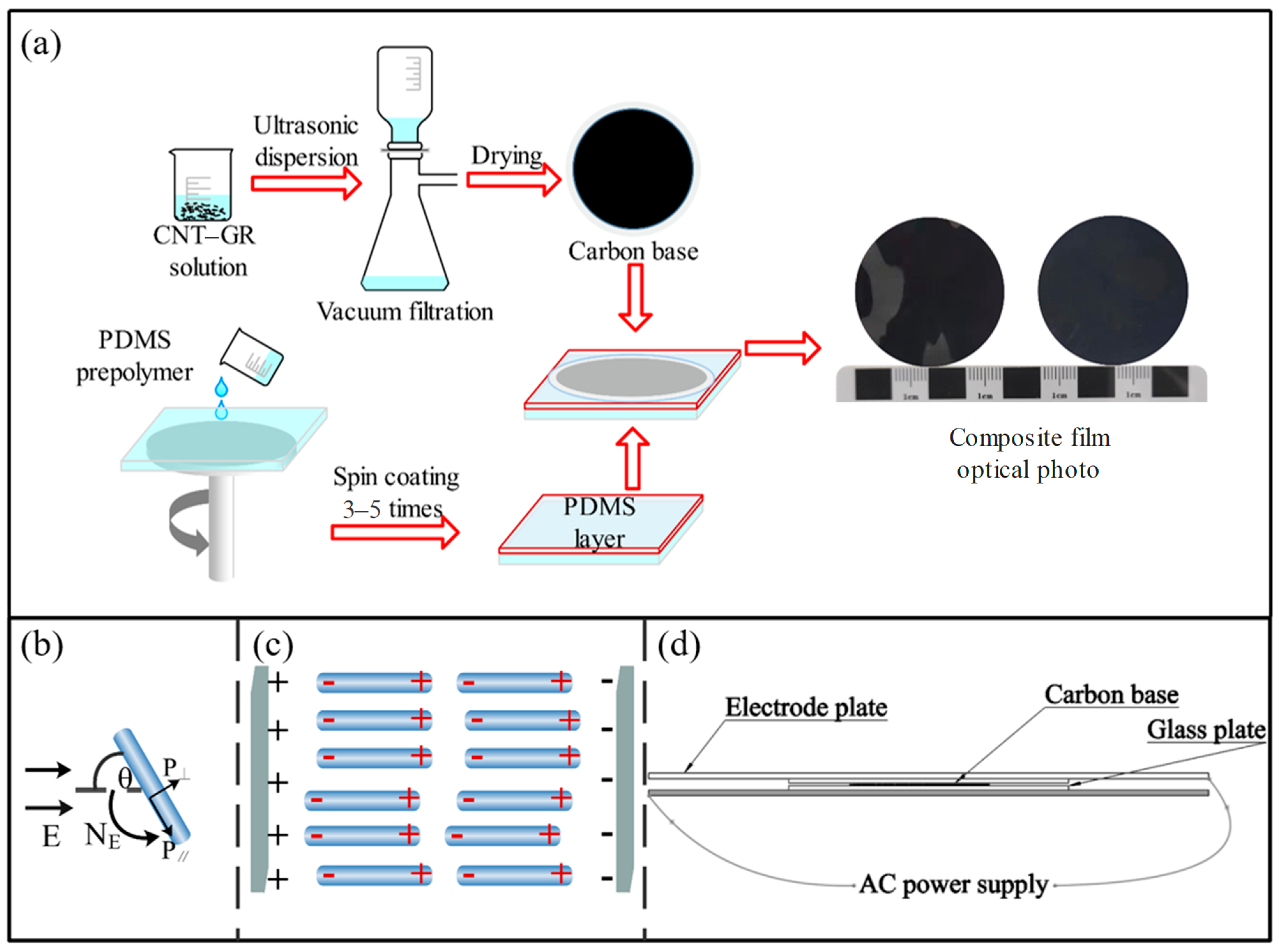
2.1. The CNT–Graphene–PDMS Composite Film’s Preparation and Electric Field Orientation

The CNTs–graphene–PDMS composite film was prepared by combining vacuum filtration and spin-coating. The carbon nanotubes and graphene were dispersed in deionized water using sodium dodecylbenzene sulfonate as a dispersant, and the dispersion was obtained by ultrasonication for 12 h. It stood still for 2 h to take the upper dispersion liquid and we used the vacuum filtration method (the filter film adopts 0.22 um nylon organic filter film) to prepare the carbon-based layer. We put the filter film with the carbon-based layer into a drying oven at 80 °C for two hours to dry. We spin-coated the PDMS at a speed of 2000 r/min, first pre-spin-coating for 15 s to cover the PDMS on the glass plate. Then, spin coating 4 times at a cycle of 10 s until the PDMS prepolymer forms a thin layer of about 2 mm thickness on the glass plate. We put the carbon-based layer with the filter film on the PDMS film layer that was spin-coated uniformly on the glass plate, and put them in a drying oven at 100 ℃ to cure for one hour. After the drying was completed, we removed the filter film, and the carbon-based layer was completely transferred to the PDMS film. A complete composite film was obtained after the above steps. The glossy side of the composite film is the insulating side, and the other side is the conductive side. Composite films with a carbon-based fixed content of 25 mg and different ratios of carbon nanotubes (graphene = 3:0, 2:1, 1:1, and 1:2) were prepared. We prepared three sets of composite membranes with the same proportion for performance testing to verify the consistency of performance. The flow chart of the experiment is shown in Figure 1a.
Oriented composite films with a carbon-based fixed content of 25 mg and carbon nanotube ratios of graphene = 3:0 and 2:1 were prepared by using an electric field. Since the carbon nanotubes are mainly oriented, the composite film with a large proportion of carbon nanotubes was selected for orientation experiments. Under the action of an external electric field, CNTs will induce an induced dipole, and the polarization effect is divided into two contribution components, P and P [21].The torque generated will tend to cause the CNT to rotate and translate in the direction of the electric field (Figure 1b). Due to the induced dipole, the positive charge inside the carbon nanotube shifts towards the negative electrode of the electric field, while the negative charge shifts towards the positive electrode of the electric field. Adjacent CNT positive and negative charges will attract each other, promoting head-to-head contact and forming an aligned structure (Figure 1c) [22]. The AC electric field is more conducive to the dispersed arrangement of carbon nanotubes than the DC electric field [23]. Using a 600 V, 400 HZ AC electric field, we placed the filtered carbon substrate between the electrode plates for orientation, as shown in Figure 1d. After drying, it was combined with PDMS film to obtain the oriented CNTs–graphene–PDMS composite film. To verify that the electrothermal performance test of the prepared composite film was not accidental, we prepared three sets of composite films with the same proportion and conducted various testing experiments to determine the consistency of their performance.

2.2. Performance Testing

The surface and cross-sectional morphological characteristics of the composite films were studied by cold field emission scanning electron microscopy (FE-SEM, Regulus 8100, Hitachi, Tokyo, Japan). Raman spectroscopy is often used to verify the arrangement of CNTs in polymer composites. The ability of individual nanotubes to collect spectra shows that the signal intensity of the CNTs produced by Raman scattering is exceptionally strong [24].The dispersion and orientation of carbon nanotubes were tested by Raman spectroscopy (Raman, Horiba Jobin Yvon Xplora, and laser wavelength 532 nm, scanning range 2000~500 cm−1) and X-ray diffraction test (XRD) (XRD, Rigaku Ultima IV, wide-angle 5–80°, conventional 10°/min). The mass change of the composite films during the heating process with a steady heating rate of 10 ℃/min in the range of 25–800 °C was analyzed by a thermogravimetric analyzer (TGA/SDTA851e); during the heating process, a constant N2 gas was used as the test atmosphere condition. The electrothermal characteristics of the composite film were tested with a FLIR thermal imaging camera (A615). The composite films were cut into a quadrilateral of 3 cm × 2.5 cm and connected to a DC power supply through a copper electrode. By applying a voltage of 1–10 V, we were able to analyze the heating rate and the maximum temperature of the composite films.

3. Results and Discussion

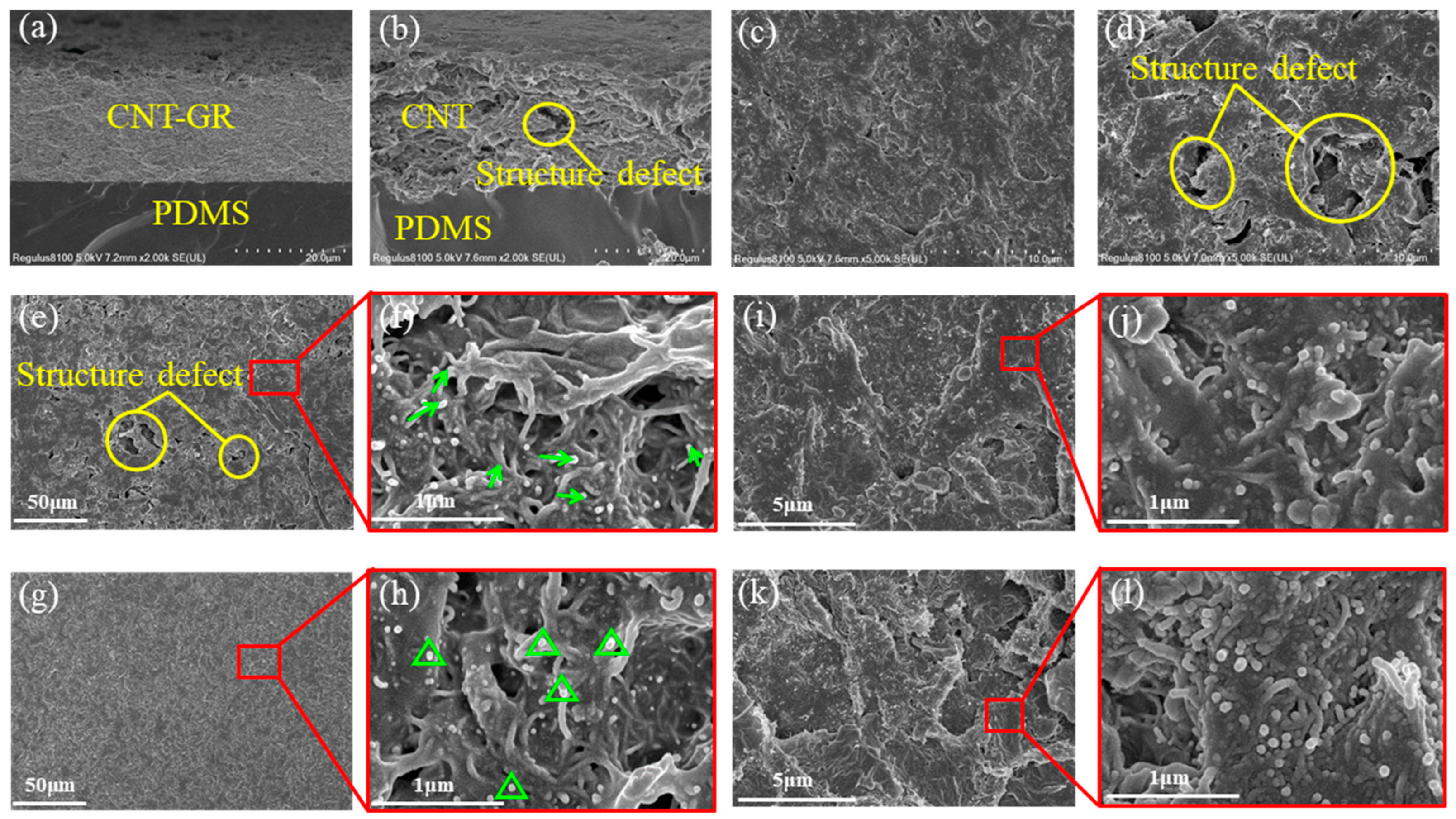
3.1. Microscopic Performance Characterization

Figure 2a,b are cross-sectional views of CNT:GR = 2:1 and CNT:GR = 3:0 composite films; it was found that the structure of the CNT:GR = 2:1 composite film was tighter. By comparing the surface Figure 2c,d, the composite film with CNT:GR = 2:1 has less structural defects. Graphene is a two-dimensional structure of sheets, while carbon nanotubes are one-dimensional tubular structures with a large aspect ratio [25,26]. The doping of graphene can fill the gap between carbon nanotubes; carbon nanotubes will be a good bridge between graphite sheet layers, thereby reducing the surface defect structure.
Comparing Figure 2e,g, the oriented CNTs–PDMS composite film is uniform, and there are almost no structural defects. Figure 2f shows that the orientation of carbon nanotubes in the CNTs–PDMS composite film is random. After the carbon nanotubes are oriented, they should be arranged along the direction of the electric field. However, because the carbon nanotubes are intertwined, it is not apparent from Figure 2h that the carbon nanotubes are completely arranged regularly. But the carbon nanotube ports (white endpoints) of the oriented CNTs–PDMS composite film are all upward, which proves that there is a tendency to align along the direction of the electric field. From Figure 2i–l, it can also be clearly seen that in the composite film with CNT:GR = 2:1 after orientation, more carbon nanotube ports are exposed, and the winding tendency becomes weaker. It proves that the electric field orientation has effect.

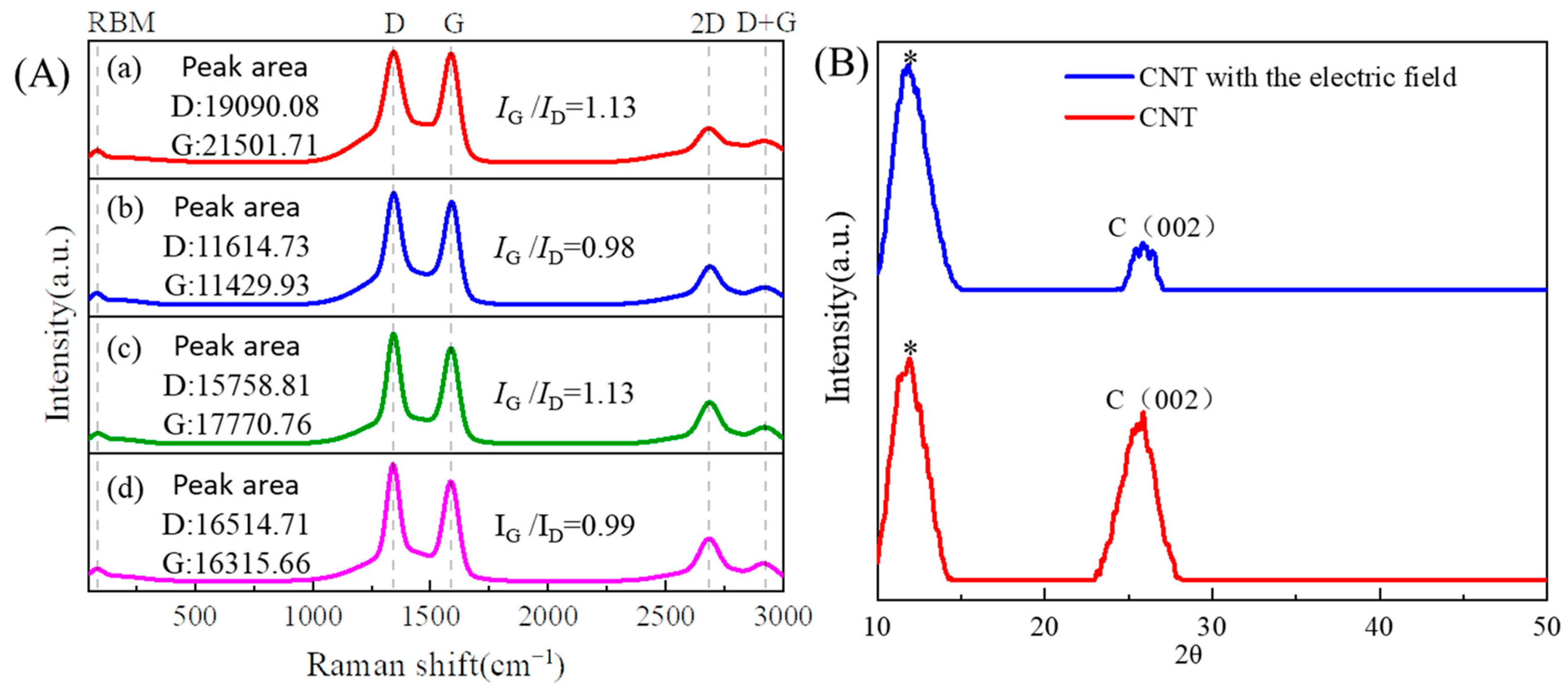
3.2. Chemical Structure Analysis

There are 6 typical peaks in the Raman spectrum of the composite film (Figure 3A). Radial breathing mode (RBM) is the radial breathing peak of carbon nanotubes, located in the low-frequency region of 100–400 cm−1 in the Raman spectrum, and is a unique vibration mode of nanotube structures [27,28]. The D peak is located near 1344 cm−1, produced by the vibration of irregular carbon atoms in carbon nanotubes, and its intensity indicates the degree of the disorder [29]. D peak has a double frequency peak around 2600 cm−1, an overtone of the D band, called the 2D peak. It should be noted that the intensity of this peak has nothing to do with the defect [30]; the G peak is located near 1590 cm−1, which results from the in-plane oscillation of sp2 carbon atoms, which can be observed in all graphite structures. This peak is used in Raman spectroscopy to assess the alignment of carbon nanotubes [31]. The D+G band is the combined overtone of the D and G bands, and defects activate this band, and its intensity increases with the degree of the disorder [32]. The ratio of the relative area of the G peak to the relative area of the D peak (IG/ID) is used to represent the degree of defects in carbon nanotubes in composite materials [33,34]. When carbon nanotubes are arranged in a regular manner, their structural defects are reduced [35]. We chose IG/ID to indirectly determine the degree of ordered arrangement of carbon nanotubes in polymer matrices under electric field orientation.
Figure 3A shows the value of IG/ID of the CNTs–graphene–PDMS composite film and the CNTs–PDMS composite film under the condition of electric field orientation and non-orientation. The IG/ID of CNTs–graphene–PDMS composite film value increased from 0.98 to 1.13, and the IG/ID value of the CNTs–PDMS composite film increased from 0.99 to 1.13. The increase in IG/ID of electric field orientation indicates that the defects of carbon nanotubes in the composite film are reduced [36]. This proved that the regularity and arrangement of carbon nanotubes were improved, and the electric field has a certain impact on the orientation and arrangement of carbon nanotubes.
As shown in Figure 3B, the diffraction peak displayed by the composite film near 11° is the amorphous phase peak of PDMS [37,38]. The C (002) peak is displayed in all graphite structures; the CNTs–PDMS composite film was selected for analysis to avoid the interference of graphene. The diffraction peak displayed by the composite film near 26.4° is the C (002) peaks of the carbon nanotube [39,40]. The C (002) peak intensity of oriented CNTs–PDMS composite film is lower than that of the unoriented composite film. This is because the C (002) peak is sharper when there are more disoriented CNTs [41], and the C (002) peak does not show up when the CNTs are fully oriented. The low-intensity C (002) peak shows that the carbon nanotubes have a certain degree of regular arrangement, but there is mutual entanglement among the carbon nanotubes, and there is a deviation in the complete arrangement. Therefore, it can be inferred that the AC electric field has an effect on the orientation of carbon nanotubes.

3.3. Electrothermal Performance

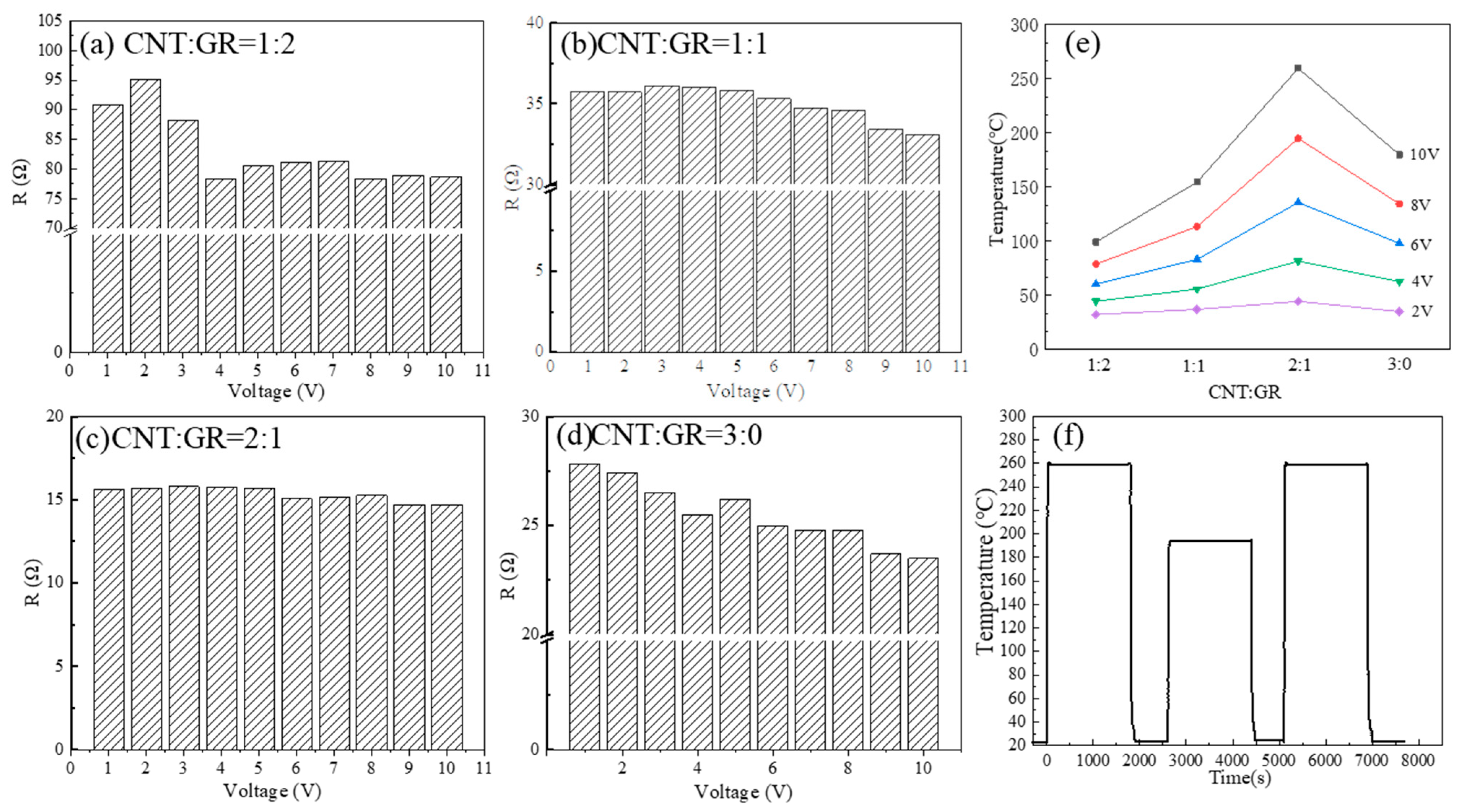
3.3.1. Effect of Voltage on Electrothermal Performance of the Composite Film

The temperature–voltage response curve is output through the electrothermal performance test. It can be seen from Figure 4a–d that when the voltage is constant, the temperature of the composite films rises to a stable temperature within the 30 s. And the stable temperature of the composite films increases with the increase of voltage. To objectively measure the composite film’s heating characteristics, the power density q is introduced:
q = P A
P = U 2 R
where P is the output power; A is the effective area of electric heating of the composite film; U is the DC power supply output voltage; and R is the resistance of the composite film, which is obtained by calculating the ratio of the output voltage to the current.
Figure 5a–d show that the power density is linearly and positively correlated with temperature. The principle of electrothermal conversion is that the current is used as the input power, and the electric energy is converted into heat energy through the Joule heating mechanism [42]. When the effective area of electric heating is fixed, the power density is proportional to U2, so the temperature is also positively related to U2. The higher the voltage, and the higher the stable temperature of the composite film.

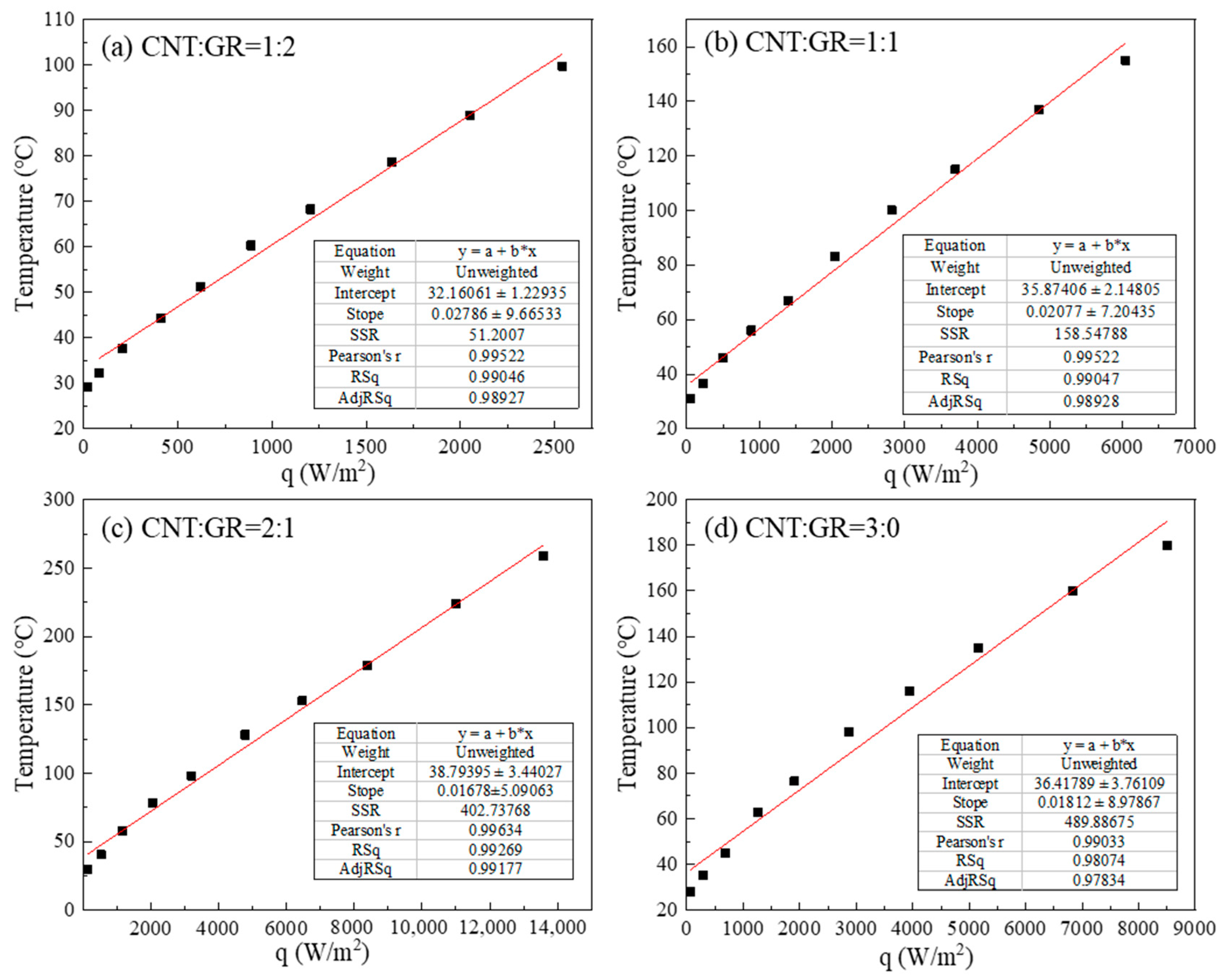
3.3.2. Effects of the Ratio of CNT to GR on the Electrothermal Performance and Cycle Temperature Stability Test

Upon comparing Figure 6a–d, we can see that the resistance of the composite film decreases with the increase of carbon nanotube content. This is because carbon nanotubes have a very high aspect ratio, which can form an excellent conductive path in the polymer [43]. However, when carbon nanotubes accounted for the entire ratio, the resistance of the composite film was higher than that of the composite film with a ratio of carbon nanotubes to graphene of 2:1. Because carbon nanotubes conduct electricity in a point–line manner and graphene conducts electricity in a point–plane manner, adding an appropriate amount of graphene can convert discontinuous carbon nanotubes into a 3D continuous network, which reduces the percolation threshold of composite film and improves electrical conductivity [44]. It has been verified by experiments that when the ratio of carbon nanotubes to graphene is 2:1, it has the lowest percolation threshold and the largest electrical conductivity. Due to its relatively complete three-dimensional conductive network and low percolation threshold, the self-thermal expansion of the thermal matrix has little effect on the dispersion of graphene and carbon nanotubes when the temperature of the composite film increases with the voltage [45]. And because the high specific surface area of graphene provides a wide range of circulation channels for electron movement, the more intense charge carrying makes the resistance change significantly after the temperature rises. Carbon nanotubes are formed by curling graphene and are intertwined with each other. Compared with graphene, carbon nanotubes have a medium specific surface area [46]. As the content of blended carbon nanotubes increases, the electronic movement is relatively weakened. And the addition of graphene can reduce the disturbance of carbon nanotubes, so the composite film with CNT:GR = 2:1 also has the best resistance stability. By comparing Figure 6e, it can be seen that as the content of carbon nanotubes increases, the stability temperature of the composite film increases. However, when the proportion of carbon nanotubes is full, the stability temperature is actually lower than that of the composite film with a ratio of carbon nanotubes to graphene of 2:1. Under a voltage of 10 V, with the increase of carbon nanotube content, the temperature changes from 99.76 °C to 154.32 °C to 259.9 °C to 179.81 °C. According to the principle of electrothermal conversion, when the voltage is constant, the smaller the resistance, and the more Joule heat generated. According to the comparative analysis of Figure 6a–d resistors, it can be concluded that the composite film with a ratio of 2:1 between carbon nanotubes and graphene has the highest conductivity, resulting in the highest Joule heat and the highest temperature generated. At the micro level, the complete conductive structure of the composite film with a 2:1 ratio of carbon nanotubes to graphene increases the number of charge carriers [47]. At the same voltage, more kinetic energy is converted into internal energy during electron collisions, resulting in higher temperatures [48].
The cyclic heating and cooling test of the composite film was carried out (Figure 6f). The temperature rise test is carried out according to the voltage of 10 V–8 V–10 V, and each test lasts for the 1800 s. The addition of graphene can alleviate the disturbance of carbon nanotubes and increase their electrothermal stability [49]. During the continuous cyclic heating test, the stable temperature remained unchanged for the 1800 s under a fixed voltage and the heating temperature is not affected by the long-term cycle test. The composite film maintained good stability electrothermal performance.

3.3.3. Influence of Electric Field Orientation on the Performance of Electrothermal

After the orientation effect of the electric field, it can be seen from Figure 7 that the heating rate of the composite film is increased by 1 °C/s, which is about 1.2 times that of the unoriented condition. This is because the effect of the electric field reduces the entanglement between the carbon nanotubes, making them more dispersed and connected, thereby reducing the insulating polymer layer between the contact points of the carbon nanotubes [50,51]. Reducing insulating polymer layer increases flow channels for electrons and phonons between carbon nanotubes in the case of the same voltage, thereby increasing the heating rate. For composite film containing only carbon nanotubes, directional action has a greater effect on the heating rate. It is attributed to the fact that the addition of graphene weakens the perturbation of carbon nanotubes.

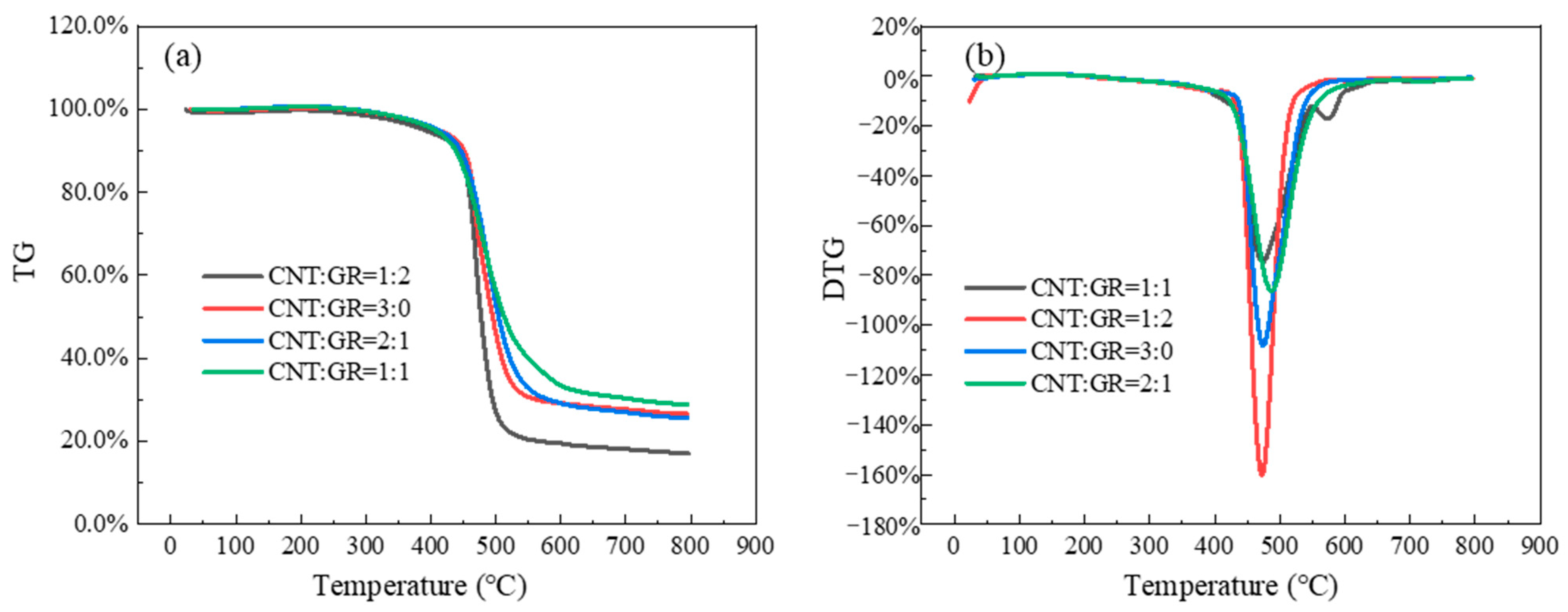
3.4. Thermal Stability Analysis

Figure 8 is the thermal stability analysis of the composite film. The decomposition temperature of the composite film is about 450 °C, as shown in Figure 8a. Under a nitrogen atmosphere, the decomposition temperature of PDMS film is about 400 °C, and it is wholly decomposed at about 600 °C [52,53]. Under a nitrogen atmosphere, the structure of carbon nanotubes and graphene is stable, and the weight loss ratio is minimal. The composite film quality changes significantly from about 450 °C and tends to be stable at about 600 °C, which is consistent with the TGA curve of PDMS. The decomposition temperature of the PDMS film with added carbon materials is somewhat higher compared with the PDMS film alone. It is considered that adding carbon nanotubes and graphene leads to stronger interactions between PDMS molecules and carbon materials. Dense chain packing at the interface interacts with PDMS, and the chain motility in the PDMS matrix is reduced [54,55]. Since the added carbon materials are different proportions of carbon nanotubes and graphene with the same mass, the interfacial interaction between the filled carbon materials and PDMS molecules is the same, so the decomposition temperature points of composite films with different proportions of carbon materials are the same, and there is no effect on the thermal stability [56]. From the comparison of the weight loss rate of each proportion of composite film in Figure 8b, it can be found that the three-dimensional structure composed of graphene and carbon nanotubes is more conducive to the structure stability of the composite film. This is because the synergistic effect of carbon nanotubes and graphene makes the network of internal materials more complex, enhancing the intermolecular forces of PDMS [57]. This leads to a tighter internal structure of the composite membrane and a decrease in its decomposition rate. Therefore, appropriately mixing graphene in carbon nanotubes can reduce the weight loss rate of the composite membrane and improve the thermal stability of the composite membrane to a certain extent.

3.5. Thermal Conductivity Analysis
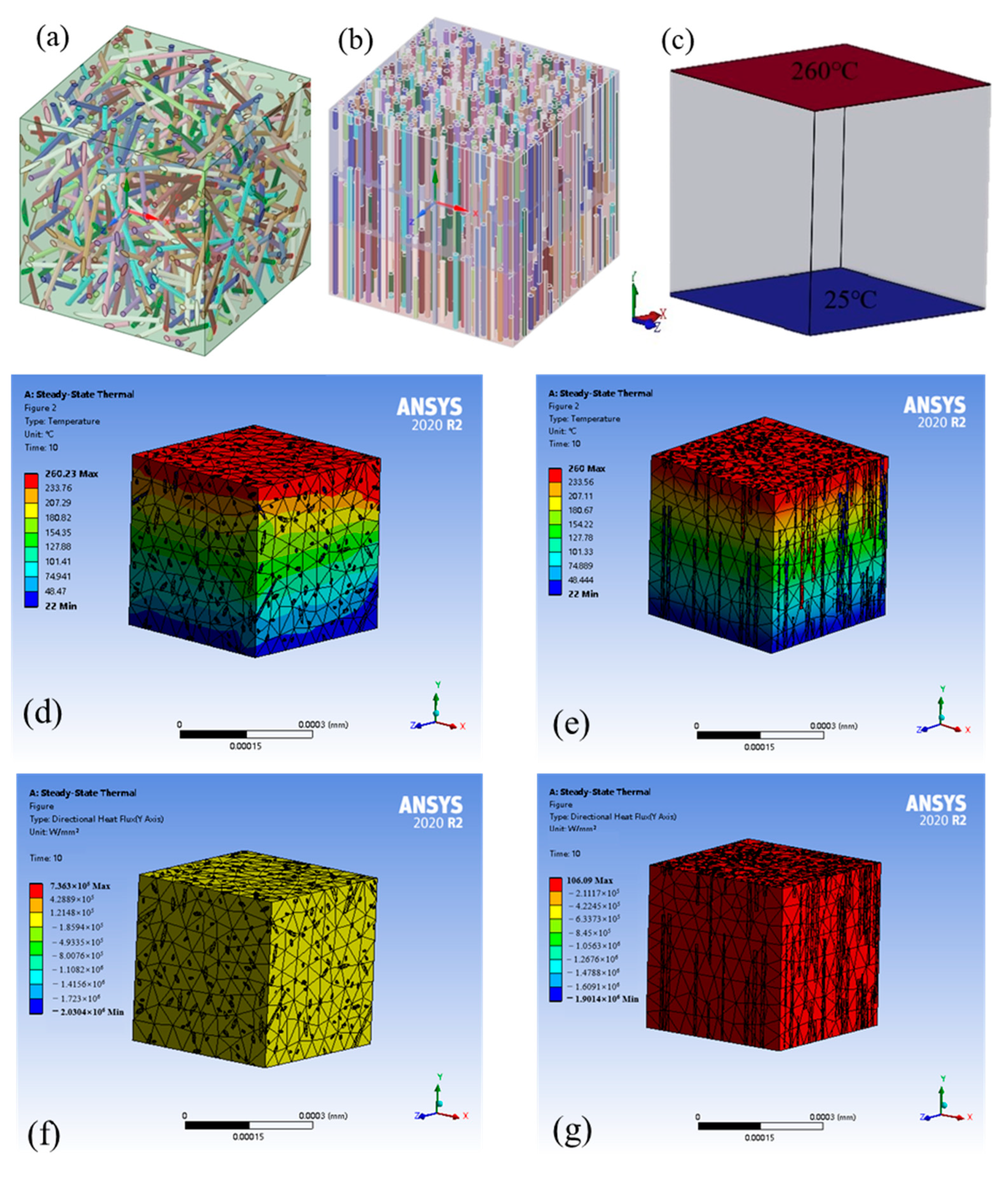
3.5.1. Simulations

The heat exchange performance of carbon nanotubes in the axial direction is very high. The heat mainly depends on the transmission of sound waves, and phonons can flow smoothly along the axial channels of carbon nanotubes. The transmission speed can reach 104 m/s [58]. Although the thermal conductivity of carbon nanotubes in the axial direction is excellent, the heat exchange performance in the radial direction is lower, so its thermal conductivity has good one-dimensional directionality [59]. This work adopted an alternating electric field to orient it so that it can be arranged axially along the direction of the electric field as much as possible. The influence of carbon nanotube orientation on the thermal conductivity of the composite film was studied through finite element analysis. Thermal simulations provide predicted values for thermal conductivity. The RVE model (Figure 9a,b) described in the paper was established using material designers in Ansys, and the thermal analysis was performed using the steady-state thermal analysis module in Ansys. In the steady-state thermal simulation of the RVE model, we adopted the following assumptions: (i) steady-state conduction, (ii) unidirectional heat flow, (iii) internal heat generated without considering contact resistance, (iv) negligible convective heat transfer ≈ 0, (v) the height and diameter of the carbon nanotubes are 400 nm and 20 nm respectively, (vi) the material is homogeneous, (vii) the unit size is 0.4 microns, and (viii) the carbon nanotubes do not touch each other.
The following are standard formulas used for thermal calculations. The heat conduction temperature and heat flux satisfy the following equation:
x λ T x + y λ T y + z λ T z = 0
q x = λ T x   q y = λ T y   q z = λ T z  
where qx, qy, and qz are the heat flux densities of the cell in each direction of x, y, and z, λ is the effective thermal conductivity, and ∂T/∂x, ∂T/∂y, and ∂T/∂z are the temperature gradients in x, y, and z directions.
Temperature of 260 °C was loaded, and 25 °C was applied to the upper and lower sides along the y-axis direction (Figure 9c), and the remaining four surfaces were set as adiabatic surfaces. We ensured that heat was conducted along the y-axis.
T | y = 0 = 25   ° C   T | y = 0 = 260   ° C
d T d y | x = 0 = 0   d T d y | x = L = 0   d T d z | z = 0 = 0   d T d z | z = L = 0
The formula for calculating the thermal conductivity is:
λ = q a v g × L T
where qavg is the average directional heat flux along the y-axis calculated by the simulation, L is the length of the RVE cell, and ∆T is the temperature difference.
From comparing Figure 9c,d, the temperature gradient is less and the temperature transfer speed is faster for the model of oriented CNTs–PDMS composite film. Figure 9f,g show the y directional total heat flow for the two models. The average heat flow of the unoriented model is 2387.1 W/mm2, and the average heat flow of the oriented model is 1.28 × 10⁵ W/mm2. The thermal conductivity of the unoriented model is calculated by the formula to be 4.63 W/(m·K). The thermal conductivity of the oriented model is 217.86 W/(m·K). Due to the arrangement of carbon nanotubes in the oriented composite film model, its structure is simpler than that of the unoriented composite film model. The scattering of the lattice wave is smaller, and the mean free path of phonons is larger, resulting in high thermal conductivity [60]. Thermal conductivity simulation studies confirm the axial orientation of carbon nanotubes to facilitate heat transfer.

3.5.2. Experiment

The measured data of the thermal diffusivity and the calculated thermal conductivity values based on the experimental data are shown in the Table 1.
Experiments have the same rules as simulations. However, there is a significant difference between the simulated and experimental values of thermal conductivity. In the simulation, it was set that the bonding contact between individual carbon nanotubes in the RVE model. CNTs can conduct heat transfer according to the thermal conductivity of 3000 W/(m·K), and the established carbon nanotubes are all short fibers, where there is no reunion winding. However, the PDMS matrix has the function of packaging and separating carbon nanotubes, and the intertwining and agglomeration of carbon nanotubes in the actual composite film is inevitable. Therefore, some carbon nanotubes cannot contact each other and cannot achieve the high thermal conductivity of itself. The complex network formed between the entire nanocomposite results in very low thermal conductivity values. The carbon nanotubes in the orientation model synthesized by the simulation process in this paper are arranged vertically, but, according to Raman and XRD analysis, there is still a certain degree of disorder in the carbon nanotube system. CNTs are intertwined, not completely vertically aligned, and cannot conduct heat in the ideal axial direction, so even the actual test value and simulation of the thermal conductivity of the oriented composite film have significant differences. In actual experiments, this carbon nanotube composite always showed lower values, which were also verified by Kumanek et al. [61]. Due to some limitations of the software, it is also impossible to provide accurate experimental values to improve the simulation effect.
Through experiments, the thermal diffusivity of two sets of oriented composite films with different ratios was tested to calculate the actual thermal conductivity. The two sets of composite films with different ratios have the same law as the simulation results: the composite films oriented by an AC electric field have a larger thermal conductivity. This verified the authenticity of the simulation. The experimental results show that the thermal conductivity of CNT:GR = 2:1 composite film is higher than that of CNT:GR = 3:0 composite film. The thermal conductivity of filled polymer-based composites mainly depends on high thermal conductivity fillers. The selection of thermal conductive fillers affects the thermal conductivity of filled thermal conductive polymers, including the size, shape, content, and distribution of fillers. The key to improving thermal conductivity is whether the filler can form a large number of continuous channels inside the polymer matrix and maintain a stable existence. When the filling amount is small, efficient and high thermal conductivity channels cannot be formed, and heat conduction still relies on the matrix. When the filling amount exceeds a certain threshold, the fillers are in contact with each other and are distributed in a network shape inside the matrix to form a continuous heat conduction network. For two sets of composite films with different proportions, the filling amount of carbon material is sufficient to conduct heat conduction. However, the composite film of CNT:GR = 2:1 forms a synergistic effect of the point–line–plane structure of graphene and carbon nanotubes to form a complete three-dimensional network. This facilitates the conduction of phonons and, thus, has a relatively high thermal conductivity.

3.6. Application Prospect Analysis

The maximum heating rate of the composite membrane in this study is 9.7 °C/s, and the maximum stable temperature is 269 °C. As shown in Figure 10, the electrothermal performance of the composite film in this study meets the requirements of current common research fields. Different proportions of composite films can be selected based on the temperature requirements of specific application scenarios, and the output temperature can be adjusted according to the voltage. Application of insulation for transportation pipelines such as gas under low temperature conditions; deicing of car and aircraft window glass heaters; wearable electronic devices such as electric heating gloves, knee pads, constant temperature masks, and constant temperature warm clothing; embedded in walls or floors for building insulation; and heating and insulation in industrial production.

4. Conclusions

This work prepared CNTs–graphene–PDMS composite film by the combination of vacuum filtration and spin coating. And we used electric field to orient CNTs to improve the electrothermal performance of the composite film. The feasibility of the composite film application was verified by experiments and simulations. This study resulted in the following conclusions:
(1)
The stable temperature of the composite film is proportional to U2. By adjusting the applied voltage, the stable temperature of the composite film can be controlled well. The temperature response time of the composite film is rapid, and it can rise to a stable temperature within 30 s and exhibit long-term running stability;
(2)
With the continuous adjustment of the ratio of carbon nanotubes to graphene, when the ratio of carbon nanotubes to graphene is 2:1, it has the lowest percolation threshold and its electrothermal performance is the best. The resistance of the composite film is 15 Ω, the power density is 13,333.3 W/m2, and the stable temperature is 260 °C at 10 V;
(3)
The electric field can improve the regular arrangement of carbon nanotubes. The heating rate of the oriented composite film increases by 1 °C/s, and the thermal conductivity of the oriented composite film is greater;
(4)
The decomposition temperature of the composite film in a nitrogen atmosphere is about 450 °C. The three-dimensional structure formed by the blending of graphene and carbon nanotubes makes the PDMS film have more excellent thermal stability. And the synergistic effect of graphene and carbon nanotubes can improve the thermal conductivity of the composite film.

Author Contributions

Conceptualization, Y.D. and J.G.; Methodology, H.D. and Q.D.; Software, H.W.; Visualization, H.W.; Validation, Y.Z.; Formal analysis, Y.Z.; Resources, Y.D. and J.G.; Investigation, Y.W. and H.D.; Writing—original draft, Y.W.; Writing—review & editing, Q.S.; Supervision, Q.D.; Project administration, Q.D.; Funding acquisition, J.G. All authors have read and agreed to the published version of the manuscript.

Funding

This work was supported by the National Key Research and Development Program of China (2021YFF0600602).

Data Availability Statement

Data are contained within the article.

Conflicts of Interest

Author Youxin Wang was employed by the TianJin Lishen Battery Joint-Stock Co., Ltd. The remaining authors declare that the research was conducted in the absence of any commercial or financial relationships that could be construed as a potential conflict of interest.

References

  1. Sun, W.-J.; Zhou, C.-G.; Jia, L.-C.; Wang, Y.-Y.; Zhang, Y.-P.; Wang, T.; Yan, D.-X.; Li, Z.-M. A reliable and highly conductive carbon nanotube/thermoplastic polyurethane composite with an enhanced segregated structure for electrically driven heater applications. J. Mater. Chem. C 2020, 8, 8814–8822. [Google Scholar] [CrossRef]
  2. Wang, Z.; Zhu, Y.; Liu, X.; Zhao, Z.; Chen, J.; Jing, X.; Chen, H. Temperature self-regulating electrothermal pseudo-slippery surface for anti-icing. Chem. Eng. J. 2021, 422, 130110. [Google Scholar] [CrossRef]
  3. Chu, H.; Zhang, Z.; Liu, Y.; Leng, J. Self-heating fiber reinforced polymer composite using meso/macropore carbon nanotube paper and its application in deicing. Carbon 2014, 66, 154–163. [Google Scholar] [CrossRef]
  4. Park, C.; Kim, T.; Samuel, E.P.; Kim, Y.-I.; An, S.; Yoon, S.S. Superhydrophobic antibacterial wearable metallized fabric as supercapacitor, multifunctional sensors, and heater. J. Power Sources 2021, 506, 230142. [Google Scholar] [CrossRef]
  5. Feng, T.; Zhang, H.; Chen, G.; Hu, J.; Ning, C.; Yuan, T. Economic research on application of electric heating system based on game theory. Glob. Energy Interconnect. 2021, 4, 315–323. [Google Scholar] [CrossRef]
  6. Vertuccio, L.; De Santis, F.; Pantani, R.; Lafdi, K.; Guadagno, L. Effective de-icing skin using graphene-based flexible heater. Compos. Part B Eng. 2019, 162, 600–610. [Google Scholar] [CrossRef]
  7. Zhang, Q.; He, Z.; Fang, X.; Zhang, X.; Zhang, Z. Experimental and numerical investigations on a flexible paraffin/fiber composite phase change material for thermal therapy mask. Energy Storage Mater. 2017, 6, 36–45. [Google Scholar] [CrossRef]
  8. Wang, C.; Xia, K.; Wang, H.; Liang, X.; Yin, Z.; Zhang, Y. Advanced carbon for flexible and wearable electronics. Adv. Mater. 2019, 31, 1801072. [Google Scholar] [CrossRef]
  9. Kim, G.M.; Naeem, F.; Kim, H.K.; Lee, H.K. Heating and heat-dependent mechanical characteristics of CNT-embedded cementitious composites. Compos. Struct. 2016, 136, 162–170. [Google Scholar] [CrossRef]
  10. Jang, D.; Yoon, H.N.; Seo, J.; Park, S.; Kil, T.; Lee, H.K. Improved electric heating characteristics of CNT-embedded polymeric composites with an addition of silica aerogel. Compos. Sci. Technol. 2021, 212, 108866. [Google Scholar] [CrossRef]
  11. Zhao, Z.; Chen, H.; Liu, X.; Wang, Z.; Zhu, Y.; Zhou, Y. The development of electric heating coating with temperature controlling capability for anti-icing/de-icing. Cold Reg. Sci. Technol. 2021, 184, 103234. [Google Scholar] [CrossRef]
  12. Kang, T.J.; Kim, T.; Seo, S.M.; Park, Y.J.; Kim, Y.H. Thickness-dependent thermal resistance of a transparent glass heater with a single-walled carbon nanotube coating. Carbon 2011, 49, 1087–1093. [Google Scholar] [CrossRef]
  13. Urper, O.; Çakmak, İ.; Karatepe, N. Fabrication of carbon nanotube transparent conductive films by vacuum filtration method. Mater. Lett. 2018, 223, 210–214. [Google Scholar] [CrossRef]
  14. Kang, J.; Kim, H.; Kim, K.S.; Lee, S.K.; Bae, S.; Ahn, J.H.; Kim, Y.J.; Choi, J.B.; Hong, B.H. High-performance graphene-based transparent flexible heaters. Nano Lett. 2011, 11, 5154–5158. [Google Scholar] [CrossRef] [PubMed]
  15. Zhou, X.; Wang, L.; Yao, Y.; Jiang, Y.; Xu, R.; Wang, H.; Wu, X.; Yu, Y. Integrating Conductivity, Captivity, and Immobility Ability into N/O Dual-Doped Porous Carbon Nanocage Anchored with CNT as an Effective Se Host for Advanced K-Se Battery. Adv. Funct. Mater. 2020, 30, 2003871. [Google Scholar] [CrossRef]
  16. Yao, X.; Hawkins, S.C.; Falzon, B.G. An advanced anti-icing/de-icing system utilizing highly aligned carbon nanotube webs. Carbon 2018, 136, 130–138. [Google Scholar] [CrossRef]
  17. Haibat, J.; Ceneviva, S.; Spencer, M.P.; Kwok, F.; Trivedi, S.; Mohney, S.E.; Yamamoto, N. Preliminary demonstration of energy-efficient fabrication of aligned CNT-polymer nanocomposites using magnetic fields. Compos. Sci. Technol. 2017, 152, 27–35. [Google Scholar] [CrossRef]
  18. Nie, Y.; Yang, J.; Liu, Z.; Zhou, Z.; Ming, Y.; Hao, T. Precursor formation and crystal nucleation in stretched polyethylene/carbon nanotube nanocomposites. Polymer 2022, 239, 124438. [Google Scholar] [CrossRef]
  19. Pothnis, J.R.; Kalyanasundaram, D.; Gururaja, S. Enhancement of open hole tensile strength via alignment of carbon nanotubes infused in glass fiber-epoxy-CNT multi-scale composites. Compos. Part A Appl. Sci. Manuf. 2021, 140, 106155. [Google Scholar] [CrossRef]
  20. Sharma, A.; Tripathi, B.; Vijay, Y.K. Dramatic Improvement in properties of magnetically aligned CNT/polymer nanocomposites. J. Membr. Sci. 2010, 361, 89–95. [Google Scholar] [CrossRef]
  21. Martin, C.A.; Sandler, J.K.W.; Windle, A.H.; Schwarz, M.K.; Bauhofer, W.; Schulte, K.; Shaffer, M.S.P. Electric field-induced aligned multi-wall carbon nanotube networks in epoxy composites. Polymer 2005, 46, 877–886. [Google Scholar] [CrossRef]
  22. Oliva-Avilés, A.I.; Avilés, F.; Sosa, V.; Seidel, G.D. Dielectrophoretic modeling of the dynamic carbon nanotube network formation in viscous media under alternating current electric fields. Carbon 2014, 69, 342–354. [Google Scholar] [CrossRef]
  23. Zhang, R.P.; Zhu, Y.F.; Ma, C.; Liang, J. Alignment of carbon nanotubes in poly(methyl methacrylate) composites induced by electric field. J. Nanosci. Nanotechnol. 2009, 9, 2887–2893. [Google Scholar] [CrossRef] [PubMed]
  24. Mikhalchan, A.; Madrona, C.; Arévalo, L.; Malfois, M.; Vilatela, J.J. Improved alignment and stress transfer in CNT fibre fabrics studied by in situ X-ray and Raman during wet-drawing. Carbon 2022, 197, 368–377. [Google Scholar] [CrossRef]
  25. Feng, D.; Zhang, Y.; Zhao, Y.; Sun, S.; Tan, H.J.F. Mechanism of in-situ dynamic catalysis and selective deactivation of H2O-activated biochar for biomass tar reforming. Fuel 2020, 279, 118450. [Google Scholar] [CrossRef]
  26. Dasbach, M.; Hampp, N.A. Enhanced light absorption and through-thickness heat conduction of vertically aligned transferable carbon nanotube/silicone rubber composite films. Mater. Chem. Phys. 2021, 267, 124690. [Google Scholar] [CrossRef]
  27. Maultzsch, J.; Telg, H.; Reich, S.; Thomsen, C. Radial breathing mode of single-walled carbon nanotubes: Optical transition energies and chiral-index assignment. Phys. Rev. B 2005, 72, 205438. [Google Scholar] [CrossRef]
  28. Farhat, H.; Sasaki, K.; Kalbac, M.; Hofmann, M.; Saito, R.; Dresselhaus, M.S.; Kong, J. Softening of the radial breathing mode in metallic carbon nanotubes. Phys. Rev. Lett. 2009, 102, 126804. [Google Scholar] [CrossRef]
  29. Kim, H.-J.; Kim, D.; Jung, S.; Yi, S.N.; Yun, Y.J.; Chang, S.K.; Ha, D.H. Charge Transport in Thick Reduced Graphene Oxide Film. J. Phys. Chem. C 2015, 119, 28685–28690. [Google Scholar] [CrossRef]
  30. Vollebregt, S.; Ishihara, R.; Tichelaar, F.D.; Hou, Y.; Beenakker, C.I.M. Influence of the growth temperature on the first and second-order Raman band ratios and widths of carbon nanotubes and fibers. Carbon 2012, 50, 3542–3554. [Google Scholar] [CrossRef]
  31. Ma, B.; Rodriguez, R.D.; Ruban, A.; Pavlov, S.; Sheremet, E. The correlation between electrical conductivity and second-order Raman modes of laser-reduced graphene oxide. Phys. Chem. Chem. Phys. 2019, 21, 10125–10134. [Google Scholar] [CrossRef]
  32. Krishnamoorthy, K.; Veerapandian, M.; Yun, K.; Kim, S.J. The chemical and structural analysis of graphene oxide with different degrees of oxidation. Carbon 2013, 53, 38–49. [Google Scholar] [CrossRef]
  33. Bokobza, L.; Zhang, J. Raman spectroscopic characterization of multiwall carbon nanotubes and of composites. Express Polym. Lett. 2012, 6, 601–608. [Google Scholar] [CrossRef]
  34. Sakamoto, H.; Fujiwara, I.; Takamura, E.; Suye, S.-I. Nanofiber-guided orientation of electrospun carbon nanotubes and fabrication of aligned CNT electrodes for biodevice applications. Mater. Chem. Phys. 2020, 245, 122745. [Google Scholar] [CrossRef]
  35. Bodik, M.; Maxian, O.; Hagara, J.; Nadazdy, P.; Jergel, M.; Majkova, E.; Siffalovic, P. Langmuir-Scheaffer Technique as a Method for Controlled Alignment of 1D Materials. Langmuir 2020, 36, 4540–4547. [Google Scholar] [CrossRef] [PubMed]
  36. Cao, Q.; Han, S.J.; Tulevski, G.S.; Zhu, Y.; Lu, D.D.; Haensch, W. Arrays of single-walled carbon nanotubes with full surface coverage for high-performance electronics. Nat. Nanotechnol. 2013, 8, 180–186. [Google Scholar] [CrossRef] [PubMed]
  37. Lancastre, J.J.H.; Fernandes, N.; Margaça, F.M.A.; Miranda Salvado, I.M.; Ferreira, L.M.; Falcão, A.N.; Casimiro, M.H. Study of PDMS conformation in PDMS-based hybrid materials prepared by gamma irradiation. Radiat. Phys. Chem. 2012, 81, 1336–1340. [Google Scholar] [CrossRef]
  38. Sulym, I.; Cetinkaya, A.; Yence, M.; Çorman, M.E.; Uzun, L.; Ozkan, S.A. Novel electrochemical sensor based on molecularly imprinted polymer combined with L-His-MWCNTs@PDMS-5 nanocomposite for selective and sensitive assay of tetracycline. Electrochim. Acta 2022, 430, 141102. [Google Scholar] [CrossRef]
  39. Krishna, A.; Aravinda, L.S.; Murugan, A.; Kumar, N.S.; Sankar, M.R.; Nagahanumaiah; Reddy, K.N.; Balashanmugam, N. A study on wafer scalable, industrially applicable CNT based nanocomposites of Al-CNT, Cu-CNT, Ti-CNT, and Ni-CNT as thermal interface materials synthesised by thin film techniques. Surf. Coat. Technol. 2022, 429, 127926. [Google Scholar] [CrossRef]
  40. Aqel, A.; El-Nour, K.M.M.A.; Ammar, R.A.A.; Al-Warthan, A. Carbon nanotubes, science and technology part (I) structure, synthesis and characterisation. Arab. J. Chem. 2012, 5, 1–23. [Google Scholar] [CrossRef]
  41. Cao, A.; Xu, C.; Liang, J.; Wu, D.; Wei, B.J.C.p.l. X-ray diffraction characterization on the alignment degree of carbon nanotubes. Chem. Phys. Lett. 2001, 344, 13–17. [Google Scholar] [CrossRef]
  42. Chu, K.; Yun, D.-J.; Kim, D.; Park, H.; Park, S.-H. Study of electric heating effects on carbon nanotube polymer composites. Org. Electron. 2014, 15, 2734–2741. [Google Scholar] [CrossRef]
  43. Wang, J.; Yu, S.; Luo, S.; Chu, B.; Sun, R.; Wong, C.-P. Investigation of nonlinear I–V behavior of CNTs filled polymer composites. Mater. Sci. Eng. B 2016, 206, 55–60. [Google Scholar] [CrossRef]
  44. Zhao, Y.; Feng, D.; Zhang, Y.; Huang, Y.; Sun, S.J.F.P.T. Effect of pyrolysis temperature on char structure and chemical speciation of alkali and alkaline earth metallic species in biochar. Fuel Process. Technol. 2016, 141, 54–60. [Google Scholar] [CrossRef]
  45. Zhao, Z.; Zhu, Y.; Wang, Z.; Zhang, Y.; Zhang, K.; Chen, J.; Liu, X.; Chen, H. A biaxial stretchable, flexible electric heating composite film for de-icing. Compos. Part A Appl. Sci. Manuf. 2022, 162, 107124. [Google Scholar] [CrossRef]
  46. Sierra-Chi, C.A.; López-Manchado, M.A.; Cauich-Rodríguez, J.V.; Gamboa, F.; Oliva, A.I.; Avilés, F. Functionalization of few-layer graphene sheets and carbon nanotubes for generation of hybrids and their effect on the piezoresistive properties of polymeric nanocomposites. Synth. Met. 2022, 289, 117121. [Google Scholar] [CrossRef]
  47. Yu, X.; Kwon, E. A carbon nanotube/cement composite with piezoresistive properties. Smart Mater. Struct. 2009, 18, 055010. [Google Scholar] [CrossRef]
  48. Shit, G.C.; Mondal, A.; Sinha, A.; Kundu, P.K. Electro-osmotic flow of power-law fluid and heat transfer in a micro-channel with effects of Joule heating and thermal radiation. Phys. A Stat. Mech. Its Appl. 2016, 462, 1040–1057. [Google Scholar] [CrossRef]
  49. Feng, D.; Guo, D.; Zhang, Y.; Sun, S.; Zhao, Y.; Shang, Q.; Sun, H.; Wu, J.; Tan, H.J.C.E.J. Functionalized construction of biochar with hierarchical pore structures and surface O-/N-containing groups for phenol adsorption. Chem. Eng. J. 2021, 410, 127707. [Google Scholar] [CrossRef]
  50. Wang, T.; Jing, L.C.; Zhu, Q.; Sagadevan Ethiraj, A.; Fan, X.; Liu, H.; Tian, Y.; Zhu, Z.; Meng, Z.; Geng, H.Z. Tannic acid modified graphene/CNT three-dimensional conductive network for preparing high-performance transparent flexible heaters. J. Colloid Interface Sci. 2020, 577, 300–310. [Google Scholar] [CrossRef]
  51. Shan, X.; Zhang, H.; Liu, C.; Yu, L.; Di, Y.; Zhang, X.; Dong, L.; Gan, Z. Reusable Self-Sterilization Masks Based on Electrothermal Graphene Filters. ACS Appl. Mater. Interfaces 2020, 12, 56579–56586. [Google Scholar] [CrossRef]
  52. Ren, C.; Si, Z.; Qu, Y.; Li, S.; Wu, H.; Meng, F.; Zhang, X.; Wang, Y.; Liu, C.; Qin, P. CF3-MOF enhanced pervaporation selectivity of PDMS membranes for butanol separation. Sep. Purif. Technol. 2022, 284, 120255. [Google Scholar] [CrossRef]
  53. Xu, S.; Zhang, H.; Yu, F.; Zhao, X.; Wang, Y. Enhanced ethanol recovery of PDMS mixed matrix membranes with hydrophobically modified ZIF-90. Sep. Purif. Technol. 2018, 206, 80–89. [Google Scholar] [CrossRef]
  54. Fang, M.; Wu, C.; Yang, Z.; Wang, T.; Xia, Y.; Li, J. ZIF-8/PDMS mixed matrix membranes for propane/nitrogen mixture separation: Experimental result and permeation model validation. J. Membr. Sci. 2015, 474, 103–113. [Google Scholar] [CrossRef]
  55. Klonos, P.; Panagopoulou, A.; Bokobza, L.; Kyritsis, A.; Peoglos, V.; Pissis, P. Comparative studies on effects of silica and titania nanoparticles on crystallization and complex segmental dynamics in poly(dimethylsiloxane). Polymer 2010, 51, 5490–5499. [Google Scholar] [CrossRef]
  56. Jiang, B.; Huang, H.; Gong, W.; Gu, X.; Liu, T.; Zhang, J.; Qin, W.; Chen, H.; Jin, Y.; Liang, Z.J.A.F.M. Wood-Inspired Binder Enabled Vertical 3D Printing of g-C3N4/CNT Arrays for Highly Efficient Photoelectrochemical Hydrogen Evolution. Adv. Funct. Mater. 2021, 31, 2105045. [Google Scholar] [CrossRef]
  57. Shahzad, M.I.; Giorcelli, M.; Shahzad, N.; Guastella, S.; Castellino, M.; Jagdale, P.; Tagliaferro, A. Study of carbon nanotubes based Polydimethylsiloxane composite films. J. Phys. Conf. Ser. 2013, 439, 012010. [Google Scholar] [CrossRef]
  58. Pourasghar, A.; Chen, Z. Dual-phase-lag heat conduction in FG carbon nanotube reinforced polymer composites. Phys. B Condens. Matter 2019, 564, 147–156. [Google Scholar] [CrossRef]
  59. Yang, X.; Chen, D.; Han, Z.; Ma, X.; To, A.C. Effects of welding on thermal conductivity of randomly oriented carbon nanotube networks. Int. J. Heat Mass Transf. 2014, 70, 803–810. [Google Scholar] [CrossRef]
  60. Gnanasekaran, K.; Grimaldi, C.; With, G.; Friedrich, H. A Unified View on Nanoscale Packing, Connectivity, and Conductivity of CNT Networks. Adv. Funct. Mater. 2019, 29, 1807901. [Google Scholar] [CrossRef]
  61. Kumanek, B.; Janas, D. Thermal conductivity of carbon nanotube networks: A review. J. Mater. Sci. 2019, 54, 7397–7427. [Google Scholar] [CrossRef]
  62. Cao, Y.; Dong, J.J.P.M. Fabrication and self-sensing control of soft electrothermal actuator. Procedia Manuf. 2020, 48, 43–48. [Google Scholar] [CrossRef]
  63. Fan, Q.; Miao, J.; Tian, M.; Zhao, H.; Zhu, S.; Liu, X.; Ma, Y.; Qu, L. Low-voltage driven flexible double-layer electrothermal actuator for smart human-machine interactions. Sens. Actuators A Phys. 2020, 315, 112352. [Google Scholar] [CrossRef]
  64. Liu, W.; Sun, Y.; Cui, A.; Xia, Y.; Yan, Q.; Song, Y.; Wang, L.; Shan, G.; Wang, X. Electrothermal sterilization and self-powered real-time respiratory monitoring of reusable mask based on Ag micro-mesh films. Nano Energy 2023, 105, 107987. [Google Scholar] [CrossRef]
  65. Liu, X.-L.; Li, M.; Geng, W.-H.; Cao, W.; Tian, Y.-H.; Li, T.-Y.; Bin, P.-S.; Qian, P.-F.; Geng, H.-Z. Modified carbon nanotubes/polyvinyl alcohol composite electrothermal films. Surf. Interfaces 2023, 36, 102540. [Google Scholar] [CrossRef]
  66. Tembei, S.A.N.; Hessein, A.; Fath El-Bab, A.M.R.; El-Moneim, A.A. A low voltage, flexible, graphene-based electrothermal heater for wearable electronics and localized heating applications. Mater. Today Proc. 2020, 33, 1840–1844. [Google Scholar] [CrossRef]
  67. Tembei, S.A.N.; Kassim Ali, M.; Hessein, A.; Fath El-Bab, A.M.R.; Abd El-Moneim, A. High-performance flexible electrothermal Joule heaters from laser reduced F-N Co-doped graphene oxide with extended Sp2 networks. FlatChem 2022, 36, 100437. [Google Scholar] [CrossRef]
  68. Wang, B.; Cheng, H.; Zhu, J.; Yuan, Y.; Wang, C. A flexible and stretchable polypyrrole/knitted cotton for electrothermal heater. Org. Electron. 2020, 85, 105819. [Google Scholar] [CrossRef]
  69. Zhang, X.; Li, D.; Liu, K.; Tong, J.; Yi, X. Flexible graphene-coated carbon fiber veil/polydimethylsiloxane mats as electrothermal materials with rapid responsiveness. Int. J. Lightweight Mater. Manuf. 2019, 2, 241–249. [Google Scholar] [CrossRef]
  70. Zhao, Z.; Yan, C.; Li, D.; Tang, X.; Ran, J.; Bi, S.; Cheng, D.; Cai, G.; Wang, X. Fabrication of rGO/Cu NPs on knitted fabrics for action sensing and electrothermal applications. Surf. Interfaces 2023, 36, 102600. [Google Scholar] [CrossRef]
  71. Wu, J.; Wang, H.; Qiu, J.; Shao, J.; Zhang, K.; Yan, L. Electrochemical exfoliation for few-layer graphene in molybdate aqueous solution and its application for fast electrothermal film. Prog. Nat. Sci. Mater. Int. 2020, 30, 312–320. [Google Scholar] [CrossRef]
  72. Yan, J.; Jeong, Y.G. Highly elastic and transparent multiwalled carbon nanotube/polydimethylsiloxane bilayer films as electric heating materials. Mater. Des. 2015, 86, 72–79. [Google Scholar] [CrossRef]
Figure 1. (a) Preparation of composite membrane experiment flow chart; (b) CNTs rotate in the direction of the electric field; (c) CNTs are arranged in the direction of the electric field; and (d) electric field orientation experimental diagram.
Energies 17 00046 g001
Figure 2. SEM images of composite films (a) CNT:GR = 2:1 cross-section; (b) CNT:GR = 3:0 cross-section; (c) CNT:GR = 2:1 surface; (d) CNT:GR = 3:0 surface; (e,f) CNT:GR = 3:0 surface; (g,h) oriented CNT:GR = 3:0 surface; (i,j) CNT:GR = 2:1 surface; and (k,l) oriented CNT:GR = 2:1 surface. (Arrows indicate the direction of carbon nanotubes. Triangles are used to indicate vertical carbon nanotubes).
Energies 17 00046 g002
Figure 3. (A) Raman spectra of composite films: (a) oriented CNTs–graphene–PDMS composite film; (b) CNTs–graphene–PDMS composite film; (c) oriented CNTs–PDMS composite film; and (d) CNTs–PDMS composite film. (B) XRD pattern of carbon nanotube–PDMS composite film. (“*” indicates other peaks that have no impact on the study.)
Energies 17 00046 g003
Figure 4. Composite films temperature–voltage response curve: (a) CNT:GR = 1:2, (b) CNT:GR = 1:1, (c) CNT:GR = 2:1, and (d) CNT:GR = 3:0.
Energies 17 00046 g004
Figure 5. Power density–temperature fitting curve of composite films: (a) CNT:GR = 1:2, (b) CNT:GR = 1:1, (c) CNT:GR = 2:1, and (d) CNT:GR = 3:0. (The red line represents the fitting line and the black dots represent the raw data).
Energies 17 00046 g005
Figure 6. (ad) Resistance of composite films; (e) temperature curves of composite films, and (f) 10 V–8 V–10 V cyclic heating–cooling curve of composite film with CNT:GR = 2:1.
Energies 17 00046 g006
Figure 7. Comparison of heating curves between oriented and non oriented composite films: (a) CNT:GR = 3:0 (5 V); (b) CNT:GR = 3:0 (8 V); (c) CNT:GR = 3:0 (10 V); (d) CNT:GR = 2:1 (5 V); (e) CNT:GR = 2:1 (8 V); (f) CNT:GR = 2:1 (10 V).
Energies 17 00046 g007
Figure 8. (a) TGA curves of the composite films; and (b) DTG curves of the composite films.
Energies 17 00046 g008
Figure 9. RVE model of (a) CNTs–PDMS composite film; (b) oriented CNTs–PDMS composite film; (c) schematic diagram of heat conduction; temperature distribution of (d) unoriented carbon nanotubes; (e) oriented carbon nanotubes; total heat flux of (f) unoriented carbon nanotube composite film; and (g) oriented carbon nanotube composite film.
Energies 17 00046 g009
Figure 10. Application analysis of heating rate and stable temperature [1,4,9,10,14,62,63,64,65,66,67,68,69,70,71,72].
Energies 17 00046 g010
Table 1. Calculated value of thermal conductivity.
NameCNT:GR = 3:0CNT:GR = 2:1
Typeunorientedorientedunorientedoriented
α0.7140.8230.7851.266
Λ (W/m·K)1.021.181.131.82
Disclaimer/Publisher’s Note: The statements, opinions and data contained in all publications are solely those of the individual author(s) and contributor(s) and not of MDPI and/or the editor(s). MDPI and/or the editor(s) disclaim responsibility for any injury to people or property resulting from any ideas, methods, instructions or products referred to in the content.

