Article

Highly Efficient Layer-by-Layer Organic Photovoltaics Enabled by Additive Strategy

1
Key Laboratory of Luminescence and Optical Information, Ministry of Education, Beijing Jiaotong University, Beijing 100044, China
2
School of Mechanical, Electronic and Control Engineering, Beijing Jiaotong University, Beijing 100044, China
3
College of Physics and Electronic Engineering, Taishan University, Taian 271021, China
4
Tangshan Research Institute, Beijing Jiaotong University, Tangshan 063000, China
*
Authors to whom correspondence should be addressed.
These authors contributed equally to this work.
Energies 2024, 17(16), 4022; https://doi.org/10.3390/en17164022
Submission received: 4 July 2024 / Revised: 2 August 2024 / Accepted: 8 August 2024 / Published: 14 August 2024

Abstract

:
In this work, layer-by-layer organic photovoltaics (LbL OPVs) were prepared by sequentially spin-coating PM1 and L8-BO solutions. The solvent additive 1,8-diiodooctane (DIO), which has a high boiling point, and solid additive l,3,5-trichlorobenzene (TCB), which has a high volatile, were deliberately selected to incorporate with the L8-BO solutions. The power conversion efficiency (PCE) of LbL OPVs was considerably enhanced from 17.43% to 18.50% by employing TCB as the additive, profiting by the concurrently increased short-circuit current density (JSC) of 26.74 mA cm−2 and a fill factor (FF) of 76.88%. The increased JSCs of LbL OPVs with TCB as additive were ascribed to the tilted-up absorption edge in the long wavelength range and the external quantum-efficiency spectral difference between LbL OPVs with and without TCB as an additive. The molecular arrangement of L8-BO and the PM1 domain was enhanced with TCB as an additive, which was most likely responsible for the increased charge mobilities in the layered films processed with additives. It was indicated that the dynamic film-forming process of the acceptor layers plays a vital role in achieving efficient LbL OPVs by employing additive strategy. Over 6% PCE improvement of the LbL OPVs with PM1/L8-BO as the active layers can be achieved by employing TCB as additive.

1. Introduction

Utilizing bulk heterojunction or layer-by-layer structures, particularly by implementing the ternary strategy in the fabrication of active layers, has resulted in notable progress in the performance of organic photovoltaics (OPVs), achieving a power conversion efficiency (PCE) exceeding 19% [1,2,3]. Bulk heterojunction (BHJ) is commonly considered an efficient active layer with a bi-continuous charge transport network, effective dissociation of excitons and charge transport that can be gained by optimizing the degree of phase separation [4,5,6]. In recent years, the layer-by-layer (LbL) OPVs were commonly prepared using a sequential spin-coating approach, which also exhibits an acceptable or superior PCE as compared to the BHJ OPVs made with identical donor and acceptor materials. Some typical works on LbL OPVs have been carried out to clarify the dynamic process of donor/acceptor active layers [7]. What is remarkable is that the stability of LbL OPVs can also be enhanced due to their more stable phase separation in comparison with BHJ OPVs under the same conditions [8,9,10,11,12]. How to improve the exciton dissociation efficiency and charge transport should be key issues for achieving efficient LbL OPVs. Xu et al. reported a smart strategy that involves incorporating appropriate acceptor materials into a donor layer to enhance the exciton dissociation efficiency near the ITO electrode [13]. Ma et al. proposed a dissociation-strengthening layer strategy to improve the exciton dissociation efficiency near the ITO based on the device structure of ITO/PEDOT:PSS/ultrathin Y6/D18-Cl/Y6/PDIN/Ag; the inserted ultrathin Y6 layer can lead to the PCE being increased from 17.62% to 18.15% [14]. Tian et al. also reported a strategy of integrating a donor into the acceptor layer, which is used to improve exciton utilization near the cathode [15]. The efficiency of LbL OPVs can be enhanced by adding 10 wt% PM1 to the L8-BO layer, raising it from 18.02% to 18.81%. This rise is attributed to the improved separation of excitons within the L8-BO layer, resulting in a more suitable donor/acceptor interface that facilitates rapid charge transfer. It is well known that applying the appropriate additive and post-annealing procedures to active layers has been proven to be an effective approach to enhancing the performance of BHJ OPVs [16,17,18,19,20]. The active layer-forming process should strongly affect the performance of the LbL OPVs fabricated through the sequential spin-coating method, especially for the acceptor layers [21,22,23,24,25]. Employing the additive strategy to adjust the film-forming process for ameliorating exciton utilization in the acceptor layer should be a simple and effective solution for improving the performance of LbL OPVs.
Focusing on the acceptor layer optimization of LbL OPVs, additive strategy was employed in this work. The impacts of different additives on the acceptor film-forming process were compared, as they strongly influence the exciton and charge dynamic processes of OPVs. A series of LbL OPVs were fabricated with a structure of ITO/PEDOT:PSS/PM1/L8-BO/PNDIT-F3N/Ag. Two additives TCB with highly volatile and DIO with a high boiling point were deliberately added into L8-BO solutions for optimizing the dynamic process of the acceptor layers. Figure 1a depicts the materials’ chemical structures and energy levels. The absorption spectra of the pure films after normalization and the layered films are presented in Figure 1b and 1c, respectively. The absorption spectra of PM1 and L8-BO are obviously complementary, which could be conducive to harvesting more photons in the visible and near-infrared regions. The addition of solid additive TCB or solvent additive DIO can slightly adjust the photon harvesting of the layered films. The ability of photon harvesting in PM/L8-BO films can be marginally enhanced by employing a DIO or a TCB additive. Meanwhile, the absorption edge of the absorption spectra PM1/L8-BO films is slightly tilted up by employing an additive. The photon-harvesting ability in the visible light range is decreased by employing both the DIO and the TCB additive. The more balanced photon-harvesting ability and range of PM1/L8-BO are the prerequisites for reaching a higher performance of LbL OPVs. The champion PCE of 18.50% can be obtained from the LbL OPVs as a TCB additive, originating from a short-circuit current density (JSC) of 26.74 mA cm−2, an open-circuit voltage (VOC) of 0.90 V and a fill factor (FF) of 76.88%. This champion PCE of the LbL OPVs should be attributed to the improved method of photon harvesting and molecular arrangement. An over 6% PCE improvement of the LbL OPVs is possible to provide by employing TCB as additive. The 18.50% PCE should be among the highest-performing LbL OPVs, with PM1/L8-BO as the active layers. This work is intended to provide more insight into the dynamic process of film formation, which is helpful for the construction of high-performance LbL OPVs.

2. Materials and Methods

2.1. Materials

The patterned indium tin oxide (ITO, 99.9%)-coated glass substrates (15 Ω per square, 110 nm) were acquired from the South China Science and Technology Co., Ltd., Shenzhen, China. The poly(3,4-ethylenedioxythiophene):poly(styrene sulfonate) (PEDOT:PSS) was bought from H.C. Starck Co., Ltd., Shanghai, China. The polymer donor PM1 was purchased from Organtec Ltd., Beijing, China. The small molecule accepter L8-BO was obtained from Solarmer Materials, Inc., Beijing, China. The 1,3,5-Trichlorobenzene (1,3,5-TCB, 99%) was bought from Bailingwei Technology Co., Ltd., Beijing, China. The 1,8-Diiodooctane (DIO) was acquired from Sigma-Aldrich, Ltd., Shanghai, China. The Poly[[2,7-bis(2-ethylhexyl)-1,2,3,6,7,8-hexahydro-1,3,6,8-tetraoxobenzo[lmn][3,8]phenanthroline-4,9-diyl]-2,5-thiophenediyl [9,9-bis [3-(dimethylamino)propyl]-9H-fluorene-2,7-diyl]-2,5-thiophenediyl (PNDIT-F3N) was purchased from eFlexPV, Ltd., Shenzhen, China. The methanol (anhydrous, 99.9%) was purchased from Thermo Fisher Scientific, Inc., Shanghai, China. The acetic acid (99–100%) was purchased from the Shanghai Aladdin Biochemical Technology Co., Ltd., Shanghai, China. The chloroform (CF, 99%) was purchased from the Xinhengyan Technology Co., Ltd., Beijing, China. A table of designation for the related materials is provided in Table S1.

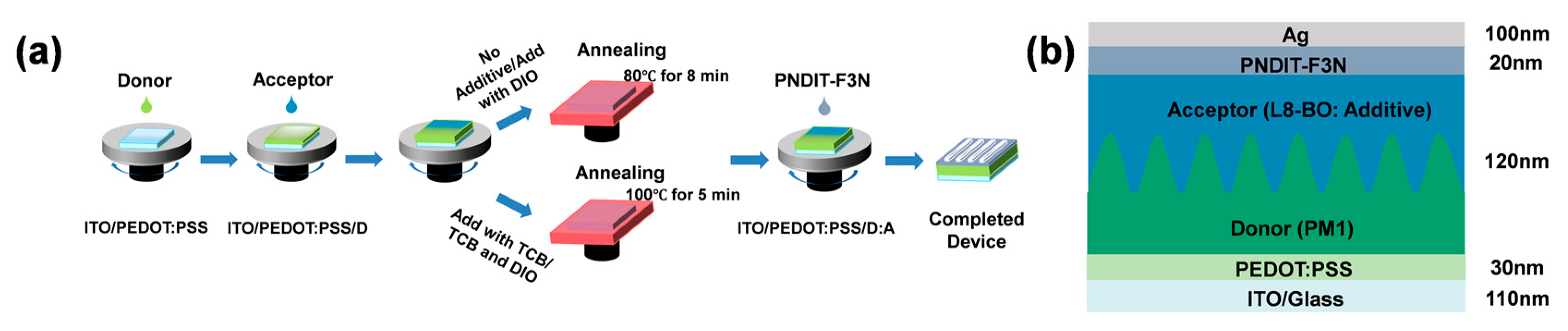
2.2. Device Fabrication

The power of the Ultrasonic cleaning machine was 360 W. The ITO substrates were sonicated for 2 h, 1 h and half an hour with washing solution, deionized water and absolute ethanol. After washing, the ITO-coated glass was blow-dried by using high-purity nitrogen gas without heating. All ITO substrates underwent a 1-min oxygen plasma treatment to enhance their work functions and cleanliness. Next, the PEDOT:PSS solution was coated on the ITO substrates at a speed of 5000 rpm for 40 s, followed by drying at 150 °C in ambient air for 15 min. The sheet resistance of PEDOT:PSS was 46 Ω sq−1. Then, the ITO substrates with the PEDOT:PSS films were transferred to a glove box filled with high-purity nitrogen. The polymer donor PM1 was dissolved in chloroform to prepare the donor solutions with a concentration of 8 mg/mL. The molecule acceptor L8-BO was mixed with chloroform to prepare the acceptor solutions with a concentration of 8 mg/mL. The 1,3,5-TCB and the DIO were added to the L8-BO solution as additives, separately and together. The additive TCB was dissolved in the L8-BO solutions in a concentration of 10 mg/mL, and 0.25 vol% DIO was added into the L8-BO solutions as an additive 15 min before spin coating.
The process diagram of the sample processing methods is shown in Figure 2a. Diagrams of the LbL-type device structures and the thicknesses of each layer are displayed in Figure 2b. Spinning at a speed of 2800 rpm for 35 s, the donor layer was coated onto the PEDOT:PSS layer. The devices were annealed at 80 °C for 8 min. The acceptor layer was deposited onto the donor layers through spin-coating, with the acceptor solutions at 3000 rpm for 35 s. Then, the devices with DIO and those without additives were heat-treated for 8 min at 80 °C, and the devices with TCB and with both additives were heat-treated for 5 min at 100 °C, respectively. The mixture of PNDIT-F3N was diluted with methanol and acetic acid (0.25 vol%) to produce a solution with a concentration of 0.5 mg/mL. The PNDIT-F3N solution was coated on the active layer at speed of 2000 rpm for 35 s. Eventually, a 100 nm Ag layer was deposited onto the surface via thermal evaporation. The active area was around 3.6 mm2.

2.3. Characterization

The current–voltage (J-V) characteristic curves of the LbL OPVs were determined in a glove box with high-purity nitrogen using a Keithley 2400 source meter, purchased from Tektronix Company, Shanghai, China. The solar simulator (AAA grade, 70 × 70 mm2 beam size) model XES-40S2 manufactured by SAN-EI Electric Co., Ltd., Osaka, Japan, offers an irradiance of 100 mW cm−2 under AM 1.5 G conditions. It was calibrated using a standard monocrystalline silicon reference solar cell. Using the Zolix Solar Cell Scan 100 instrument (Zolix INSTRUMENTS Co., Ltd., Beijing, China) and Shimadzu UV-3101 PC spectrometer (SHIMADZU Corporation, Kyoto, Japan), the external quantum efficiency (EQE) spectra and the absorption spectra of the films were recorded, respectively [26,27,28]. Using an electrochemical workstation from Germany, the electrochemical impedance spectroscopy was assessed. Transient photovoltage (TPV) and transient photocurrent (TPC) measurements were performed using the Paioscarrier measurement system from FLUXiM AG, Winterthur, Switzerland. The Dimension Icon AFM (Bruker Corp., Billerica, MA, USA) was used to study the morphology of the films under an atomic force microscope (AFM) in tapping mode. Measurements of glancing incidence wide-angle X-ray scattering (GIWAXS) were performed by using the PLS-II-9A U-SAXS beamline at the Pohang Accelerator Laboratory in Pohang, South Korea.

3. Results

Under AM 1.5 G illumination with 100 mW cm−2 intensity, the J-V curves of all LbL OPVs were observed, as illustrated in Figure 3a. The key photovoltaic parameters of the LbL OPVs are outlined in Table 1. The basic device’s JSC was 25.89 mA cm−2, VOC was 0.92 V, FF was 73.16% and the achievable PCE was 17.43%. The PCE of 17.98% were in LbL OPVs with DIO; they were derived from the improvements in JSC to 26.27 mA cm−2 and in FF to 77.77%, together with the decreased VOC of 0.88 V. The markedly increased FF and JSC of the LbL OPVs indicate that photogenerated electrons and holes can be efficiently transported and collected by employing a DIO additive in an L8-BO solution. The crystallinity of the L8-BO layer could have been enhanced during the slow film-forming process because of the elevated boiling point of the DIO [29]. The PCEs of the LbL OPVs were raised from 17.43% to 18.50% through the addition of TCB to the L8-BO solution, which benefitted from the JSC being synergistically increased to 26.74 mA cm−2 and from the FF being increased to 76.88%, as well as the VOC being slightly decreased (0.92 V vs. 0.90 V). It should be highlighted that the JSC and VOC of the LbL OPVs with TCB as an additive are larger than the corresponding parameters of the LbL OPVs with the added DIO. The JSC and VOC of the LbL OPVs with both TCB and DIO as additives are markedly decreased in comparison with the LbL OPVs without or with one additive, leading to a 17.06% PCE of the LbL OPVs with the use of both TCB and DIO as additives. The series resistances (RS) and shunt resistances (RSH) of the LbL OPVs were extracted from J-V curves, and the impact of the additives on the FF of the LbL OPVs was further discussed, as illustrated in Table 1. It can be observed that the LbL OPVs with DIO as the additive obtained a smaller RS of 2.4 Ω cm2 and a higher RSH of 1090 Ω cm2, indicating that the optimized LbL OPVs have more effective charge transport, providing a clear justification for the FF being markedly improved from 73.16% to 77.77%.
The EQE spectra of the LbL OPVs with or without additive were evaluated and are presented in Figure 3b. It became clear that the EQE spectra of devices with additive exhibited a slight red-shifted trend, which is the main reason for the JSCs’ increment due to the improvement in photon capture during the long wavelength range, as confirmed from the tilted-up absorption edge of the PM1/L8-BO layered films with additive, shown in Figure 1c. Efficient photon harvesting in the long-wavelength spectrum is crucial for enhancing the performance of the OPVs. This phenomenon has also been observed in the ternary OPVs; the tilted-up absorption edge of the active layers can result in the improved PCE of the ternary OPVs [30]. To visually demonstrate the contribution of additive, the EQE spectral discrepancy (ΔEQE) between the OPVs without additive and the optimal OPVs with TCB as an additive were calculated, as shown in Figure 3b. The integrated JSCs show an analogical trend to the measured JSC values, as outlined in Table 1. Positive values of ΔEQE across the entire spectral range imply the enhanced photon utilization efficiency of PM1/L8-BO with TCB as an additive. The calculated JSC enhancement is 0.86 mA cm−2 according to the ΔEQE spectrum, which is in accordance with the measured JSC increase from 25.89 mA cm−2 to 26.74 mA cm−2. The improved photon utilization could be attributed to the ameliorative molecular arrangement of L8-BO with TCB as the nucleating agent, enhancing the efficiency of charge transportation and collection [31].
To gain an understanding of how the additives impact the exciton and charge dynamic processes, the photogenerated current density (Jph) versus the effective voltage (Veff) characteristic curves of LbL OPVs were recorded, as depicted in Figure 4a. The Jph is equal to the current density under standard solar illumination conditions (JL) minus the density under dark conditions (JD) [32,33,34]. The Veff can be described as the voltage V0 at Jph = 0 mA cm−2 minus the applied voltage Va. Jsat is primarily determined by the quantity of photons collected by the active layer [35]. The current density at the short-circuit and the maximum power output conditions are represented by Jph* and Jph&, respectively. Jph is the saturation current density (Jsat) defined at a Veff of 4 V [36]. The optimized OPVs with TCB as an additive have a relatively large Jsat of 27.26 mA cm−2, indicating that more photons were captured by PM1/L8-BO with TCB as an additive. The Jph*, Jph&, Jsat, ηD and ηC of all the LbL OPVs are detailed in Table S2. Evaluating Jph*/Jsat and Jph&/Jsat is a method for understanding the exciton dissociation efficiency (ηD) and charge collection efficiency (ηC). The detailed ηD values of the LbL OPVs were 98.74% (without additive), 98.87% (DIO), 98.09% (TCB) and 97.69% (TCB + DIO), respectively. The detailed ηC values of the LbL OPVs were 86.77% (without additive), 91.44% (DIO), 92.19% (TCB) and 93.38% (TCB + DIO), respectively. The ηD marginally increased by employing TCB or DIO as additives; in comparison with the LbL OPVs without additives, all the ηD values were larger than 98%. The ηC of the LbL OPVs with TCB as an additive is 92.19%, which is higher than the 86.77% of the LbL OPVs without any additive and 91.44% of the OPVs with DIO as an additive. According to the previous report [31], TCB can promote the L8-BO self-assembly by hydrogen bonding with L8-BO molecules. The ηC of the LbL OPVs was increased to 93.38% and the ηD of LbL OPVs was decreased to 97.69% by employing TCB and DIO as additives. Achieving the well balanced ηC and ηD of LbL OPVs was accomplished by using TCB as an additive.
For a more thorough investigation of the charge transfer properties of the active layer, the impedance spectroscopy of the LbL OPVs was measured in the frequency range of 5 Hz to 5 MHz under an applied voltage equal to VOC. The equivalent circuit models and the Nyquist plots of the LbL OPVs with and without different additives are displayed in Figure 4b; the continuous lines indicate the outcomes of the fitting procedure. ROS is a parasitic series resistor and RCT is the charge transfer resistance; the capacitance parameter (CPE-T) and non-uniform constant (CPE-P) collectively govern the characteristics of the constant phase element (CPE) [37,38,39]. The CPE-P parameter ranges from 0 to 1, indicating pure resistance at one end and ideal capacitance at the other. The fitted parameters of the LbL OPVs are presented in Table S3. The ROS of the LbL OPVs was reduced from 51.6 Ω to about 42 Ω by employing an additive in the L8-BO layer. The RCT values were reduced from 36.2 Ω to 26.8 Ω with DIO, 28.1 Ω with TCB and 29.1 Ω with TCB and DIO as additives in L8-BO layer. The decreased RCT and ROS of the LbL OPVs indicate that charge recombination can be efficiently suppressed by employing the additive strategy, leading to the FF enhancement of LbL OPVs with additives. The process of charge transfer can be analyzed using a formula to calculate the time constants (τ) linked to the interfacial charge transfer [25]:
τ = RCT × CPE-T
The calculated τ values are presented in Table S3. The decreased τ values show that the charge transfer times in OPVs with additive are lower than those of the LbL OPVs without additive, which suppress charge recombination for FF improvement.
In order to deeply understand the charge extraction and charge recombination dynamics of the LbL OPVs, the decay curves of TPC were drawn under short-circuit conditions, and the TPV decay curves were performed under open-circuit conditions [40,41], as depicted in Figure 4c,d. The TPC and TPV decay curves can be used to extract the charge extraction time (τext) and the photocarrier lifetime (τpho) of the LbL OPVs, respectively [28,42]. The τext values of the LbL OPVs were reduced from 0.33 μs to 0.29 μs by the DIO additive, to 0.26 μs by the TCB additive and to 0.31 μs by the TCB and DIO additives. The decreased τext values indicate that a higher charge transport as well as a higher collection efficiency were observed. The τpho values were raised from 6.18 μs to 6.85 μs by the DIO additive, to 7.94 μs by the TCB additive and to 6.41 μs by the TCB and DIO additives, which means that a lower carrier recombination was caused by employing additive in the L8-BO layer. As compared with the LbL OPVs without additives, the shorter τext and longer τpho of the LbL OPVs with additive can promote the extraction of charge and inhibit the recombination of charge, resulting in the markedly improved FFs of the LbL OPVs.
The ln(Jd3/V2) – (V/d)0.5 curves of hole-only and electron-only devices are displayed in Figure 5; the detailed hole mobility (μh) and electron mobility (μe) are summarized in Table S4. The results indicate that additive strategy can simultaneously enhance both the μh and μe of the LbLs’ active layers. The μh and μe of the PM1/L8-BO were enhanced to 9.41 × 10⁻⁴ and 9.32 × 10⁻⁴ cm2 V−1 s−1 by employing DIO as an additive accompanied by a more equal ratio of μh/μe at 1.01. The more balanced μh/μe of PM1/L8-BO with the DIO additive should lead to the highest FF of 77.77%, fulfilled by the corresponding LbL OPVs. The μh and μe of the PM1/L8-BO layers were 9.42 × 10⁻⁴ and 8.60 × 10⁻⁴ cm2 V−1 s−1 by employing TCB as additive, which provided a good explanation for the relatively low FF of 76.88% for the OPVs with TCB as an additive. The μh and μe of the PM1/L8-BO layers were further increased to 1.10 × 10⁻³ and 9.70 × 10⁻⁴ cm2 V−1 s−1 by adding TCB and DIO as additives; the charge transport becomes unbalanced due to the relatively large μh/μe of 1.13. It is important to emphasize that FF is codetermined by the charge mobility and μh/μe and a higher charge mobility and a balanced μh/μe lead to the higher FF of the OPVs.
The layered films, with and without additive, were identified using AFM as depicted in Figure 6a. The roughness values of the root-mean-square (RMS) treated with additives were higher than those of the as-cast layered films, signifying the formation of more obvious aggregated structures for efficient charge transport. To gain a better understanding of the impact of different additives on a molecular arrangement of neat and layered films, the GIWAXS characterization was enacted [24,43,44,45,46,47]. 2D GIWAXS images and extracted 1D diffraction profiles focusing on the directions of in-plane (IP) and out-of-plane (OOP) for pure PM1 and L8-BO films are exhibited in Figure S1 and Figure 6b, respectively. The diffraction peaks of IP (100) and OOP (010) can be simultaneously discovered in both tidy PM1 films and L8-BO films, showing that the molecular packings of PM1 and L8-BO are more inclined toward face-on orientation. In addition to the diffraction peaks of OOP (010) and IP (100), a new and obvious diffraction peak in OOP (100) can also be seen in the L8-BO films processed with TCB, indicating that a 3D molecular orientation of L8-BO was formed and provided more electron transport channels. When the L8-BO films were processed with DIO, multiple and sharp diffraction peaks can be observed, indicating the long-range-ordered and highly crystalline molecular packing of the L8-BO. Meanwhile, the position of the OOP (010) diffraction peak for the L8-BO films moves slightly toward the direction of the higher diffraction vector enabled by the DIO addition, indicating a more tightly packed π-π stacking for effective electron transport. The positive effect of the two additives on the molecular packing of the L8-BO molecules can be simultaneously seen during the TCB + DIO treatment of acceptor films, as evidenced by the multiple and sharp diffraction peaks of IP (100), OOP (100) and OOP (010), along with the redshifted OOP (010) diffraction peak of L8-BO. TCB, DIO and TCB + DIO can each serve as morphology regulators, when added to the acceptor, they can ameliorate L8-BO’s molecular arrangement. In order to further confirm the positive impact of additives on the molecular arrangements of layered films, a GIWAXS characterization with and without additives were performed, as exhibited in Figure 6c. The presence of distinct diffraction peaks at IP (100) and OOP (010) in the layered film demonstrates that films prefer a face-on orientation of PM1/L8-BO. The diffraction peaks of IP (100) or OOP (010) in the PM1/L8-BO films mainly originate from PM1 or L8-BO, respectively, due to the location of the peaks in layered films, which are very similar to those of corresponding neat films. The molecular crystal coherence length (CCL) values can be computed in line with the equation: CCL = 2πk/fwhm. The k and fwhm represent the Scherrer constant, which is approximately 0.9. The diffraction peak width is half of its maximum intensity [48,49,50,51,52]. The CCL values associated with the π-π or lamellar stacking in layered films can concurrently rise from 16.62 Å or 30.72 Å to 21.98 Å or 53.12 Å, 18.18 Å or 51.38 Å, 22.13 Å or 55.41 Å by incorporating DIO, TCB, or DIO + TCB as additives, respectively. The increased values connected to the π-π interactions and lamellar stacking result in the higher molecular crystallinity of the L8-BO and PM1 domains, which can effectively explain the increased electron and hole charge mobilities in layered films processed with additives. The CCL value of the L8-BO layer with both TCB and DIO additives is the highest. The device with TCB and DIO as additives had a reduced performance, corresponding to the more unbalanced μh/μe value of 1.13, indicating that excessive molecular crystallinity has a negative impact on the molecular arrangement. All the different diffraction peaks’ vector (q) values and the crystal coherence lengths (CCLs) of the layered films are outlined in Table S5.

4. Conclusions

In summary, on the basis of the polymer donor PM1 and the small molecular acceptor L8-BO, strings of LbL OPVs were established by using the sequential spin-coating; the only difference was whether the L8-BO solutions were with or without DIO, TCB or TCB + DIO as additive. An efficiency of 18.50% was reached in the LbL OPVs using TCB as additive, profiting by the 26.74 mA cm2 JSC, the 0.90 V VOC and the 76.88% FF. The improvement of the PCE was closely related to the additive strategy. The increased JSCs of the LbL OPVs using TCB as an additive was attributed to the EQE spectral red-shift in the long wavelength range due to the L8-BO molecular arrangement optimization through TCB as a morphology regulator. The increased FF of the LbL OPVs with the TCB additive must be ascribed to the molecular crystallinity and arrangement optimization of the L8-BO and PM1 domains with TCB as the morphology regulator. The formation of the 3D molecular orientation of the L8-BO should provide more electron transport channels, which can explain the higher charge mobility with TCB as an additive. This work offers a more thorough insight into the process of the dynamic film forming of acceptor layers by building high-performance LbL OPVs with the additive strategy.

Supplementary Materials

The following supporting information can be downloaded at https://www.mdpi.com/article/10.3390/en17164022/s1, Table S1: The designations of main materials; Figure S1: 2D-GIWAXS images and GIWAXS intensity distributions of the PM1 films along the IP (blue lines) and OOP (red lines) directions; Table S2: Device parameters obtained from Jph-Veff curves of LbL OPVs; Table S3: The fitted parameters of LbL OPVs; Table S4: The μh, μe and μh/μe values of neat and layered films; and Table S5: The various vector (q) values corresponding to diffraction peaks and CCL of layered films.

Author Contributions

Conceptualization, J.W., X.M. and F.Z.; methodology, Y.N. and H.T.; software, Y.N. and H.T.; validation, Y.N., R.G. and W.X.; formal analysis, Y.N. and H.Z.; investigation, Y.N. and H.T.; writing—original draft preparation, Y.N. and X.M.; writing—review and editing, F.Z.; funding acquisition, X.M. and F.Z. All authors have read and agreed to the published version of the manuscript.

Funding

This work is supported by the Fundamental Research Funds for the Central Universities (2024YJS186), the National Natural Science Foundation of China (Grant Nos. 62175011, 62105017 and 62205276) and the Natural Science Foundation of Hebei Province (F2023105002).

Data Availability Statement

The original contributions presented in the study are included in the article/Supplementary Material, further inquiries can be directed to the corresponding authors.

Conflicts of Interest

The authors declare no conflicts of interest.

References

  1. Guo, Y.; Li, D.; Gao, Y.; Li, C. Recent Progress on Stability of Organic Solar Cells Based on Non-Fullerene Acceptors. Acta Phys. Chim. Sin. 2023, 40, 2306050. [Google Scholar] [CrossRef]
  2. Jee, M.; Ryu, H.; Lee, D.; Lee, W.; Woo, H. Recent Advances in Nonfullerene Acceptor-Based Layer-by-Layer Organic Solar Cells Using a Solution Process. Adv. Sci. 2022, 9, 2201876. [Google Scholar] [CrossRef]
  3. Li, Y.; Huang, W.; Zhao, D.; Wang, L.; Jiao, Z.; Huang, Q.; Wang, P.; Sun, M.; Yuan, G. Recent Progress in Organic Solar Cells: A Review on Materials from Acceptor to Donor. Molecules 2022, 27, 1800. [Google Scholar] [CrossRef] [PubMed]
  4. Yang, B.; Zhang, C.; Wang, Y.; Zhang, M.; Liu, Z.; Wu, Y.; Chen, H. Theoretical study on organic photovoltaic heterojunction FTAZ/IDCIC. Chin. J. Chem. Phys. 2023, 36, 199–210. [Google Scholar] [CrossRef]
  5. Xu, X.; Li, Y.; Peng, Q. Ternary Blend Organic Solar Cells: Understanding the Morphology from Recent Progress. Adv. Mater. 2022, 34, 2107476. [Google Scholar] [CrossRef]
  6. Inganäs, O. Organic Photovoltaics over Three Decades. Adv. Mater. 2018, 30, 1800388. [Google Scholar] [CrossRef]
  7. Zhou, M.; Liao, C.; Duan, Y.; Xu, X.; Yu, L.; Li, R.; Peng, Q. 19.10% Efficiency and 80.5% Fill Factor Layer-by-Layer Organic Solar Cells Realized by 4-Bis (2-Thienyl) Pyrrole-2,5-Dione Based Polymer Additives for Inducing Vertical Segregation Morphology. Adv. Mater. 2023, 35, 2208279. [Google Scholar] [CrossRef]
  8. Ning, H.; Jiang, Q.; Han, P.; Lin, M.; Zhang, G.; Chen, J.; Chen, H.; Zeng, S.; Gao, J.; Liu, J.; et al. Manipulating the solubility properties of polymer donors for high-performance layer-by-layer processed organic solar cells. Energy Environ. Sci. 2021, 14, 5919–5928. [Google Scholar] [CrossRef]
  9. Hu, M.; Zhang, Y.; Liu, X.; Zhao, X.; Hu, Y.; Yang, Z.; Yang, C.; Yuan, Z.; Chen, Y. Layer-by-Layer Solution-Processed Organic Solar Cells with Perylene Diimides as Acceptors. ACS Appl. Mater. Interfaces 2021, 13, 29876–29884. [Google Scholar] [CrossRef]
  10. Wei, Y.; Chen, Z.; Lu, G.; Yu, N.; Li, C.; Gao, J.; Gu, X.; Hao, X.; Lu, G.; Tang, Z.; et al. Binary Organic Solar Cells Breaking 19% via Manipulating the Vertical Component Distribution. Adv. Mater. 2022, 34, 2204718. [Google Scholar] [CrossRef]
  11. Sun, R.; Guo, J.; Sun, C.; Wang, T.; Luo, Z.; Zhang, Z.; Jiao, X.; Tang, W.; Yang, C.; Li, Y.; et al. A universal layer-by-layer solution-processing approach for efficient non-fullerene organic solar cells. Energy Environ. Sci. 2019, 12, 384–395. [Google Scholar] [CrossRef]
  12. Liu, M.; Yao, Q.; Li, S.; Qin, Y.; Jeong, S.Y.; Ma, Y.; Shen, L.; Ma, X.; Yang, K.; Yuan, G.; et al. Interfacial Engineering for Photomultiplication Type Organic Photodetectors with Signal-Noise-Ratio over 89,000. Adv. Opt. Mater. 2024, 12, 2303216. [Google Scholar] [CrossRef]
  13. Hong, L.; Yao, H.; Cui, Y.; Bi, P.; Zhang, T.; Cheng, Y.; Zu, Y.; Qin, J.; Yu, R.; Ge, Z.; et al. 18.5% Efficiency Organic Solar Cells with a Hybrid Planar/Bulk Heterojunction. Adv. Mater. 2021, 33, 2103091. [Google Scholar] [CrossRef] [PubMed]
  14. Xu, W.; Tian, H.; Ni, Y.; Xu, Y.; Zhang, L.; Zhang, F.; Wu, S.; Jeong, S.; Huang, T.; Du, X.; et al. Eco-friendly solvent-processed layer-by-layer ternary all-polymer solar cells exhibiting over 18.5% efficiency. Chem. Eng. J. 2024, 493, 152558. [Google Scholar] [CrossRef]
  15. Ma, X.; Xu, W.; Liu, Z.; Jeong, S.; Xu, C.; Zhang, J.; Woo, H.; Zhou, Z.; Zhang, F. Over 18.1% Efficiency of Layer-by-Layer Polymer Solar Cells by Enhancing Exciton Utilization near the ITO Electrode. ACS Appl. Mater. Interfaces 2023, 15, 7247–7254. [Google Scholar] [CrossRef]
  16. Tian, H.; Xu, W.; Liu, Z.; Xie, Y.; Zhang, W.; Xu, Y.; Jeong, S.; Zhang, F.; Weng, N.; Zhang, Z.; et al. Over 18.8% Efficiency of Layer-By-Layer Organic Photovoltaics Enabled by Ameliorating Exciton Utilization in Acceptor Layer. Adv. Funct. Mater. 2024, 34, 2313751. [Google Scholar] [CrossRef]
  17. Zhang, L.; Zhang, M.; Ni, Y.; Xu, W.; Zhou, H.; Ke, S.; Tian, H.; Jeong, S.; Wong, W.; Ma, X.; et al. Over 17.1% or 18.2% Efficiency of Layer-by-Layer All-Polymer Solar Cells via Incorporating Efficient Pt Complexes as Energy Donor Additive. ACS Mater. Lett. 2024, 6, 2964–2973. [Google Scholar] [CrossRef]
  18. Chen, Q.; Huang, H.; Hu, D.; Zhang, C.; Xu, X.; Lu, H.; Wu, Y.; Yang, C.; Bo, Z. Improving the Performance of Layer-by-Layer Processed Organic Solar Cells via Introducing a Wide-Bandgap Dopant into the Upper Acceptor Layer. Adv. Mater. 2023, 35, 2211372. [Google Scholar] [CrossRef]
  19. Chen, T.; Li, S.; Li, Y.; Chen, Z.; Wu, H.; Lin, Y.; Gao, Y.; Wang, M.; Ding, G.; Min, J.; et al. Compromising Charge Generation and Recombination of Organic Photovoltaics with Mixed Diluent Strategy for Certified 19.4% Efficiency. Adv. Mater. 2023, 35, 2300400. [Google Scholar] [CrossRef]
  20. Li, C.; Gu, X.; Chen, Z.; Han, X.; Yu, N.; Wei, Y.; Gao, J.; Chen, H.; Zhang, M.; Wang, A.; et al. Achieving Record-Efficiency Organic Solar Cells upon Tuning the Conformation of Solid Additives. J. Am. Chem. Soc. 2022, 144, 14731–14739. [Google Scholar] [CrossRef]
  21. Liu, K.; Jiang, Y.; Liu, F.; Ran, G.; Huang, F.; Wang, W.; Zhang, W.; Zhang, C.; Hou, J.; Zhu, X. Organic Solar Cells with Over 19% Efficiency Enabled by a 2D-Conjugated Non-fullerene Acceptor Featuring Favorable Electronic and Aggregation Structures. Adv. Mater. 2023, 35, 2300363. [Google Scholar] [CrossRef] [PubMed]
  22. Sun, R.; Wu, Q.; Guo, J.; Wang, T.; Wu, Y.; Qiu, B.; Luo, Z.; Yang, W.; Hu, Z.; Guo, J.; et al. A Layer-by-Layer Architecture for Printable Organic Solar Cells Overcoming the Scaling Lag of Module Efficiency. Joule 2020, 4, 407–419. [Google Scholar] [CrossRef]
  23. Ding, G.; Chen, T.; Wang, M.; Xia, X.; He, C.; Zheng, X.; Li, Y.; Zhou, D.; Lu, X.; Zuo, L.; et al. Solid Additive-Assisted Layer-by-Layer Processing for 19% Efficiency Binary Organic Solar Cells. Nano Micro Lett. 2023, 15, 92. [Google Scholar] [CrossRef] [PubMed]
  24. Tian, H.; Ni, Y.; Zhang, W.; Xu, Y.; Zheng, B.; Jeong, S.; Wu, S.; Ma, Z.; Du, X.; Hao, X.; et al. Over 19.2% efficiency of layer-by-layer organic photovoltaics enabled by a highly crystalline material as an energy donor and nucleating agent. Energy Environ. Sci. 2024, 17, 5173–5182. [Google Scholar] [CrossRef]
  25. Wang, M.; Yang, L.; Xu, X.; Qin, W.; Yin, S. Improved efficiency of flexible polymer solar cells with a non-annealing active layer. J. Renew. Sustain. Energy 2014, 6, 023128. [Google Scholar] [CrossRef]
  26. Fu, H.; Peng, Z.; Fan, Q.; Lin, F.R.; Qi, F.; Ran, Y.; Wu, Z.; Fan, B.; Jiang, K.; Woo, H.Y.; et al. A Top-Down Strategy to Engineer Active Layer Morphology for Highly Efficient and Stable All-Polymer Solar Cells. Adv. Mater. 2022, 34, 2202608. [Google Scholar] [CrossRef] [PubMed]
  27. Li, C.; Zhou, J.; Song, J.; Xu, J.; Zhang, H.; Zhang, X.; Guo, J.; Zhu, L.; Wei, D.; Han, G.; et al. Non-fullerene acceptors with branched side chains and improved molecular packing to exceed 18% efficiency in organic solar cells. Nat. Energy 2021, 6, 605–613. [Google Scholar] [CrossRef]
  28. Gurney, R.; Lidzey, D.; Wang, T. A review of non-fullerene polymer solar cells: From device physics to morphology control. Rep. Prog. Phys. 2019, 82, 036601. [Google Scholar] [CrossRef]
  29. Liu, W.; Sun, S.; Zhou, L.; Cui, Y.; Zhang, W.; Hou, J.; Liu, F.; Xu, S.; Zhu, X. Design of Near-Infrared Nonfullerene Acceptor with Ultralow Nonradiative Voltage Loss for High-Performance Semitransparent Ternary Organic Solar Cells. Angew. Chem. Int. Edit. 2022, 61, e202116111. [Google Scholar] [CrossRef]
  30. Firdaus, Y.; Le Corre, V.; Karuthedath, S.; Liu, W.; Markina, A.; Huang, W.; Chattopadhyay, S.; Nahid, M.; Nugraha, M.; Lin, Y.; et al. Long-range exciton diffusion in molecular non-fullerene acceptors. Nat. Commun. 2020, 11, 5220. [Google Scholar] [CrossRef]
  31. Li, X.; Yang, H.; Du, X.; Lin, H.; Yang, G.; Zheng, C.; Tao, S. High-Performance Layer-by-Layer organic solar cells enabled by Non-Halogenated solvent with 17.89% efficiency. Chem. Eng. J. 2023, 452, 139496. [Google Scholar] [CrossRef]
  32. Liu, F.; Zhou, L.; Liu, W.; Zhou, Z.; Yue, Q.; Zheng, W.; Sun, R.; Liu, W.; Xu, S.; Fan, H.; et al. Organic Solar Cells with 18% Efficiency Enabled by an Alloy Acceptor: A Two-in-One Strategy. Adv. Mater. 2021, 33, 2100830. [Google Scholar] [CrossRef]
  33. Fu, J.; Fong, P.; Liu, H.; Huang, C.; Lu, X.; Lu, S.; Abdelsamie, M.; Kodalle, T.; Sutter-Fella, C.; Yang, Y.; et al. 19.31% binary organic solar cell and low non-radiative recombination enabled by non-monotonic intermediate state transition. Nat. Commun. 2023, 14, 1760. [Google Scholar] [CrossRef]
  34. Chen, H.; Jeong, S.; Tian, J.; Zhang, Y.; Naphade, D.; Alsufyani, M.; Zhang, W.; Griggs, S.; Hu, H.; Barlow, S.; et al. A 19% efficient and stable organic photovoltaic device enabled by a guest nonfullerene acceptor with fibril-like morphology. Energy Environ. Sci. 2023, 16, 1062–1070. [Google Scholar] [CrossRef]
  35. Yang, Y.; Feng, E.; Li, H.; Shen, Z.; Liu, W.; Guo, J.; Luo, Q.; Zhang, J.; Lu, G.; Ma, C.; et al. Layer-by-layer slot-die coated high-efficiency organic solar cells processed using twin boiling point solvents under ambient condition. Nano Res. 2021, 14, 4236–4242. [Google Scholar] [CrossRef]
  36. Cui, Y.; Yao, H.; Hong, L.; Zhang, T.; Xu, Y.; Xian, K.; Gao, B.; Qin, J.; Zhang, J.; Wei, Z.; et al. Achieving Over 15% Efficiency in Organic Photovoltaic Cells via Copolymer Design. Adv. Mater. 2019, 31, 1808356. [Google Scholar] [CrossRef] [PubMed]
  37. Wang, X.; Zhang, L.; Hu, L.; Xie, Z.; Mao, H.; Tan, L.; Zhang, Y.; Chen, Y. High-Efficiency (16.93%) Pseudo-Planar Heterojunction Organic Solar Cells Enabled by Binary Additives Strategy. Adv. Funct. Mater. 2021, 31, 2102291. [Google Scholar] [CrossRef]
  38. Sun, R.; Wu, Y.; Yang, X.; Gao, Y.; Chen, Z.; Li, K.; Qiao, J.; Wang, T.; Guo, J.; Liu, C.; et al. Single-Junction Organic Solar Cells with 19.17% Efficiency Enabled by Introducing One Asymmetric Guest Acceptor. Adv. Mater. 2022, 34, 2110147. [Google Scholar] [CrossRef] [PubMed]
  39. Xu, W.; Zhang, M.; Liu, Z.; Tian, H.; Zhang, W.; Sun, S.; Jeong, S.; Zhang, F.; Li, X.; Sun, Q.; et al. A nonfullerene acceptor as a solid additive realizing a record efficiency of 17.74% in quasi-layered all-polymer solar cells. J. Mater. Chem. A 2024, 12, 4077–4085. [Google Scholar] [CrossRef]
  40. Kaewprajak, A.; Kumnorkaew, P.; Sagawa, T. Influence of binary additives into the solvent for preparation of polymer and fullerene bulk heterojunction solar cells by convective deposition method. Org. Electron. 2019, 73, 18–25. [Google Scholar] [CrossRef]
  41. Zhao, X.; Liu, M.; Wang, J.; Yang, K.; Zhang, H.; Jeong, S.; Ma, X.; Woo, H.; Zhang, F. Dual-Band Photomultiplication-Type Organic Photodetectors with Ultrahigh Signal-to-Noise Ratios. ACS Appl. Mater. Interfaces 2024, 16, 35400–35409. [Google Scholar] [CrossRef] [PubMed]
  42. Zhu, Y.; Wang, K.; Zheng, S.; Wang, H.; Dong, J.; Li, J. Application and Development of Electrochemical Spectroscopy Methods. Acta Phys. Chim. Sin. 2023, 40, 2304040. [Google Scholar] [CrossRef]
  43. Zhao, X.; Li, X.; Liu, M.; Zhao, Z.; Yang, K.; Liu, P.; Zhang, H.; Li, J.; Ma, X.; Yao, Q.; et al. Photomultiplication-Type All-Polymer Photodetectors and Their Applications in Photoplethysmography Sensor. Acta Phys. Chim. Sin. 2024, 40, 2311021. [Google Scholar] [CrossRef]
  44. Sun, Y.; Nian, L.; Kan, Y.; Ren, Y.; Chen, Z.; Zhu, L.; Zhang, M.; Yin, H.; Xu, H.; Li, J.; et al. Rational control of sequential morphology evolution and vertical distribution toward 17.18% efficiency all-small-molecule organic solar cells. Joule 2022, 6, 2835–2848. [Google Scholar] [CrossRef]
  45. He, C.; Pan, Y.; Ouyang, Y.; Shen, Q.; Gao, Y.; Yan, K.; Fang, J.; Chen, Y.; Ma, C.; Min, J.; et al. Manipulating the D: A interfacial energetics and intermolecular packing for 19.2% efficiency organic photovoltaics. Energy Environ. Sci. 2022, 15, 2537–2544. [Google Scholar] [CrossRef]
  46. Song, J.; Zhu, L.; Li, C.; Xu, J.; Wu, H.; Zhang, X.; Zhang, Y.; Tang, Z.; Liu, F.; Sun, Y. High-efficiency organic solar cells with low voltage loss induced by solvent additive strategy. Matter 2021, 4, 2542–2552. [Google Scholar] [CrossRef]
  47. Chen, W.; Xiao, M.; Yang, C.; Duan, L.; Yang, R. Efficient P3HT:PC61BM solar cells employing 1,2,4-trichlorobenzene as the processing additives. Chin. J. Polym. Sci. 2016, 35, 302–308. [Google Scholar] [CrossRef]
  48. Liang, Q.; Chang, Y.; Liang, C.; Zhu, H.; Guo, Z.; Liu, J. Application of Crystallization Kinetics Strategy in Morphology Control of Solar Cells Based on Nonfullerene Blends. Acta Phys. Chim. Sin. 2023, 39, 2212006. [Google Scholar] [CrossRef]
  49. Liang, Q.; Li, W.; Lu, H.; Yu, Z.; Zhang, X.; Dong, Q.; Song, C.; Miao, Z.; Liu, J. Recent Advances of Solid Additives Used in Organic Solar Cells: Toward Efficient and Stable Solar Cells. ACS Appl. Energy Mater. 2023, 6, 31–50. [Google Scholar] [CrossRef]
  50. Cui, F.; Chen, Z.; Qiao, J.; Wang, T.; Lu, G.; Yin, H.; Hao, X. Ternary-Assisted Sequential Solution Deposition Enables Efficient All-Polymer Solar Cells with Tailored Vertical-Phase Distribution. Adv. Funct. Mater. 2022, 32, 2200478. [Google Scholar] [CrossRef]
  51. Cai, Y.; Li, Q.; Lu, G.; Ryu, H.; Li, Y.; Jin, H.; Chen, Z.; Tang, Z.; Lu, G.; Hao, X.; et al. Vertically optimized phase separation with improved exciton diffusion enables efficient organic solar cells with thick active layers. Nat. Commun. 2022, 13, 2369. [Google Scholar] [CrossRef] [PubMed]
  52. Fu, Y.; Lee, T.; Chin, Y.; Pacalaj, R.; Labanti, C.; Park, S.; Dong, Y.; Cho, H.; Kim, J.; Minami, D.; et al. Molecular orientation-dependent energetic shifts in solution-processed non-fullerene acceptors and their impact on organic photovoltaic performance. Nat. Commun. 2023, 14, 1870. [Google Scholar] [CrossRef] [PubMed]
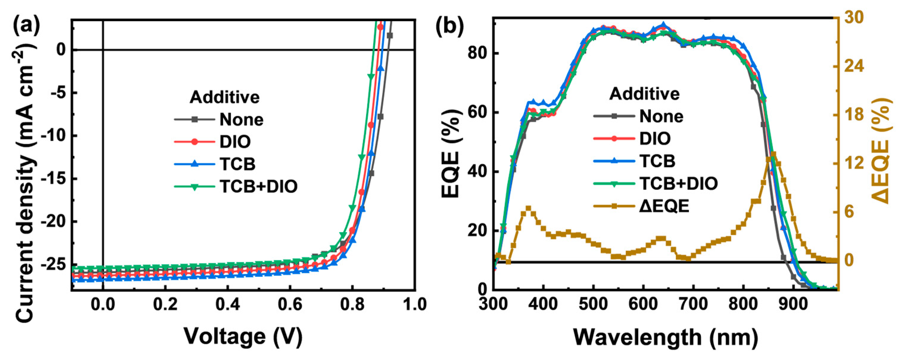
Figure 1. (a) Chemical structures of used materials and the energy levels of PM1 and L8-BO. (b) Normalized absorption spectra of PM1 and L8-BO. (c) Absorption spectra of PM1/LB-BO with and without additive.
Energies 17 04022 g001
Figure 2. (a) Diagram of the fabrication procedures for LbL OPVs. (b) Diagram of the LbL-type device structures.
Energies 17 04022 g002
Figure 3. (a) The J−V curves of typical LbL OPVs. (b) EQE spectra and ΔEQE curves of the typical LbL OPVs.
Energies 17 04022 g003
Figure 4. PM1/L8-BO films with and without additive treatment: (a) Jph versus Veff curves, (b) Nyquist plots and equivalent circuit, (c) TPC curve and (d) TPV curves.
Energies 17 04022 g004aEnergies 17 04022 g004b
Figure 5. The ln(Jd3/V2) (V/d)0.5 curves of (a) hole-only devices and (b) electron-only devices.
Energies 17 04022 g005
Figure 6. (a) The atomic force microscopy (AFM) images of layer-by-layer films. (b,c) 2D-GIWAXS images and GIWAXS intensity distributions of the corresponding ordered (b) neat and (c) typical layered films along the directions of IP (in-plane, black lines) and OOP (out-of-plane, red lines).
Energies 17 04022 g006
Table 1. Photovoltaic parameters of LbL OPVs with and without additive in the L8-BO layer.
AdditiveJSC (Ave. ± Dev.) a
(mA/cm2)
Cal. JSC
(mA/cm2)
VOC (Ave. ± Dev.) a
(V)
FF (Ave. ± Dev.) a
(%)
PCE (Ave. ± Dev.) a
(%)
RS
(Ω cm2)
RSH
(Ω cm2)
None25.89 (25.55 ± 0.34)24.570.92 (0.917 ± 0.005)73.16 (72.71 ± 0.45)17.43 (17.29 ± 0.14)2.8650
DIO26.27 (26.10 ± 0.17)25.180.88 (0.879 ± 0.002)77.77 (77.55 ± 0.22)17.98 (17.87 ± 0.11)2.41090
TCB26.74 (26.46 ± 0.28)25.430.90 (0.898 ± 0.004)76.88 (76.45 ± 0.43)18.50 (18.38 ± 0.12)2.5910
TCB + DIO25.39 (25.14 ± 0.25)25.050.88 (0.875 ± 0.006)77.21 (76.83 ± 0.38)17.06 (16.93 ± 0.13)2.7770
a Average and standard deviations were calculated from 10 individual cells.
Disclaimer/Publisher’s Note: The statements, opinions and data contained in all publications are solely those of the individual author(s) and contributor(s) and not of MDPI and/or the editor(s). MDPI and/or the editor(s) disclaim responsibility for any injury to people or property resulting from any ideas, methods, instructions or products referred to in the content.

