Article

Performance Enhancement of H-Type Darrieus VAWT Using a Hybrid Method of Blade Pitch Angle Regulation

by
Mahmood Abduljabbar Hammad
1,*,
Abdelgadir Mohamed Mahmoud
1,
Ahmed M. Abdelrhman
2 and
Shamsul Sarip
1
1
Razak Faculty of Technology and Informatics, Universiti Teknologi Malaysia, Kuala Lumpur 54100, Malaysia
2
Department of Mechanical Engineering, School of Engineering, Bahrain Polytechnic, Isa Town 33349, Bahrain
*
Author to whom correspondence should be addressed.
Energies 2024, 17(16), 4044; https://doi.org/10.3390/en17164044
Submission received: 23 July 2024 / Revised: 11 August 2024 / Accepted: 13 August 2024 / Published: 15 August 2024
(This article belongs to the Section A3: Wind, Wave and Tidal Energy)

Abstract

:
Blade pitch angle regulation is an effective approach to enhance the performance of H-type Darrieus Vertical Axis Wind Turbines (VAWTs). Improving the blade interaction with the wind for this type of rotor is a challenging task, especially in unsteady wind conditions. This paper presents a novel hybrid approach that integrates fixed and variable blade pitch angle regulation techniques, aiming to enhance the wind turbine efficiency across various operational stages and wind speeds. The proposed blade pitch angle regulation method targets a less complicated, mechanically feasible, and cost-effective pitching technique. This study uses the Double Multiple Streamtube (DMST) model to analyze the aerodynamic performance and calculate the power output generated at different pitch angles. MATLAB Simulink was utilized to implement the DMST model, and experimental validation was conducted to confirm the results. The findings indicate that the blade pitch angle regulation has significantly enhanced the self-starting ability of H-type Darrieus VAWT by 80%. Additionally, the maximum rotational speed and power coefficient are achieved at a zero pitch angle. Furthermore, regulating the blade pitch angle allows for the effective control of excessive rotational speeds during high wind conditions.

1. Introduction

Wind energy is a cornerstone of the global renewable energy portfolio, offering a powerful solution to reduce greenhouse gas emissions and decrease reliance on fossil fuels [1]. Among several wind turbine configurations, the H-type Darrieus Vertical Axis Wind Turbine is known for its ability to operate in various environmental settings, including urban areas where wind experiences high fluctuations [2]. Unlike Horizontal Axis Wind Turbines (HAWTs), H-type Darrieus VAWTs do not require a yaw mechanism to align the rotor with the wind direction, making them ideal for areas with inconsistent wind patterns. This advantage improves the H-type VAWTs capability in residential zones where noise and space are highly considered [3]. The performance of H-type Darrieus VAWTs remains a critical concern, influencing their adoption within the market [4]. Also, these wind turbines face major challenges, particularly a low self-start ability and the need for powerful overspeed control in the case of high wind conditions. The self-starting issue develops as a result of the aerodynamic properties of these wind turbine blades, which usually fail to produce sufficient torque to overcome the inertia at the starting stage, especially at low wind speeds. This issue can lead to a decrease in the overall wind turbine efficiency [5]. Overspeed control is another significant challenge that occurs during high wind events, where the rotational speed of the rotor exceeds safe operational limits. This can cause mechanical stress and potential damage to the wind turbine components [6]. Ensuring better performance is vital for maximizing energy capture, reducing operational costs, and increasing the reliability of wind turbines [7]. Different authors have suggested blade pitch angle regulation to improve the performance of H-type VAWTs [6,8,9,10,11]. The blade pitch angle rotates the wind turbine blades’ tips either towards the inside (negative pitching) or outside (positive pitching) of the circle trajectory, thus providing control over the angle of attack (Figure 1). The value of the pitch angle adjustment changes based on various factors such as the blade profile, turbine dimensions, wind speed, and rotational speed. Since the pitch angle directly influences the angle of attack (AOA), it also affects the drag and lift coefficients, subsequently impacting the torque and the rotational speed of the rotor.
By utilizing the blade pitch angle, the H-type VAWTs can achieve better aerodynamic efficiency and can solve various operational challenges such as low starting torque [4]. Blade pitch angle regulation is mainly divided into two types: Fixed Pitch (FP) and Variable Pitch (VP). Fixed pitch blade angle regulation involves setting the blades at a constant Pitch Angle (β) [12]. This method is preferred for its low cost and durability as it eliminates the need for complex moving mechanisms and moving parts required in variable blade pitch angle systems. Also, a fixed pitch angle reduces the mechanical moving parts, making the rotor experience fewer mechanical failures. Furthermore, the simplicity of FP design reduces the manufacturing and installation costs, making these turbines a suitable choice for consumers with budget constraints [13]. However, the trade-off for this simplicity is a decrease in efficiency, especially in inconsistent wind conditions. Fixed blade pitching is not able to adapt to changes in wind speeds, leading to a reduction in the performance of the H-type Darrieus VAWTs [6]. The fixed pitch angle technique may not be beneficial during some operational stages, as it is designed to operate efficiently only within a specific range of wind conditions [14]. Even though fixed pitch angle regulation might not be effective in all operational conditions, studies have mentioned that an increase in the Power Coefficient (CP) can be achieved when the blade pitch angle is accurately adjusted to match the prevailing wind conditions of a specific location [15,16]. On the other hand, variable blade pitch angle regulation for H-type Darrieus VAWTs is an advanced method developed to enhance the turbine performance for various wind conditions. This technique allows the rotor to maintain better aerodynamic efficiency by adjusting the blade based on the wind speed and direction, therefore maximizing the Lift Coefficient (CL) and Drag Coefficient (CD) [17]. By continuously adjusting the blades’ pitching angle, the rotor can operate closer to its optimal performance curve in a wider range of wind speeds, significantly increasing the overall energy generation when compared to FP systems [16]. Another considerable benefit of variable blade pitch regulation is its ability to improve wind turbine self-starting capabilities [18]. The VP technique can adjust the blade to a pitching angle that maximizes the torque generated during the initial rotation [19]. This ability is a preferable advantage for residential and urban settings where inconsistent wind conditions might occur [20]. Moreover, the dynamic adjustment of the blade pitch angle provides better load management during high wind events. VP systems can utilize the blade pitching angle to reduce the effect of an excessive wind load on the rotor structure, thus protecting it from potential damage and reducing mechanical components’ wear and tear [21]. Studies have highlighted that approximately 20–30% improvement in the power coefficient can be achieved depending on the specific design and operational conditions [16,18,22,23]. Sagharichi et al. (2016) pointed out that VP systems can adapt to turbulent wind conditions more effectively than FP systems, where this not only enhances energy capture, but also stabilizes output power consistency during H-type Darrieus VAWT operations [16]. With all stated advantages of VP systems, the complexity of these systems raises some disadvantages. The need for powerful control systems, mechanical mechanisms, actuators, and sensors increases the operational cost and the initial investment price [24,25,26]. These extra components must be engineered precisely and maintained regularly to ensure a reliable performance [6]. Such an extra cost might be unjustified for small-scale H-type Darrieus VAWTs where the energy generation is relatively low; therefore, the payback period will be significantly extended.
The blade pitch angle selection method for H-type Darrieus VAWTs is a crucial aspect of wind turbine design that highly impacts performance and efficiency. This method includes identifying the optimum pitch angle at which the blade should be adjusted to maximize the aerodynamic efficiency for specific wind conditions. Computational Fluid Dynamics (CFD) simulations were utilized to predict and analyze the performance of different pitch angles for various wind speeds [27]. By modeling the aerodynamic forces acting on the blade, CFD helps engineers and researchers to determine the blade pitch angle that provides the best balance between lift and drag, thus improving energy capturing [10]. To ensure the effectiveness of these simulations, the results of these models are usually validated by experimental testing in wind tunnels and field experiments [28,29]. The selection process includes different factors such as rotor structural dynamics and operational conditions. Optimization algorithms and machine learning are increasingly being integrated into the pitch angle selection process, allowing for more adaptive and precise control that can act in real-time to changing conditions [4,30,31]. The selection of the blade pitch angle is heavily influenced by the blade pitching technique. For a fixed pitch angle, the process is very simple, as the blade will be either moved towards the inside or outside of the circle trajectory by a fixed amount for all wind conditions. In contrast, a variable blade pitch is more complex; for instance, it might include sinusoidal blade pitching over the azimuth positions to ensure energy balance between the upstream and downstream parts of the rotor [16], or a customized technique might be used based on the available wind [10]. These VP techniques can significantly improve the performance of the H-type Darrieus VAWTs; however, this adds more complexity and cost to the system. This study aims to develop a hybrid pitching method combining fixed and variable blade pitch angle techniques that enhance the H-type Darrieus VAWT efficiency across all operational stages. Also, this study targets a less complicated, mechanically feasible, and cost-effective blade pitch regulation technique. This study will use the DMST model to conduct aerodynamic analyses and calculate the power output at different pitch angles. The DMST model will be implemented in MATLAB Simulink (R2022b) and validated through experimentation.

2. Solution Strategy

This study proposes a hybrid blade pitching technique that uses a fixed pitch angle for all azimuth positions at a specific rotational speed (Figure 2). The pitch angle (β) changes based on the rotational speed (ω). As the rotor’s rotational speed increases towards the ideal rotational speed (ωIdeal), the pitch angle will decrease. For instance, at the start of the wind turbine where ( ω = 0 ), the pitch angle will be at its maximum (β = βMax); this will provide more interaction between the blade and the wind, facilitating easier self-starting of the turbine. Furthermore, as the rotor’s rotational speed increases towards excessive levels due to high wind speeds, blade pitching is also used to control the rotational speed. When the wind turbine operates at the ideal rotational speed, the blade pitch angle will be equal to zero as the turbine will have the highest power coefficient at a zero pitch angle. The selection of the blade pitch angle is determined using Equation (2) in Section 4.4. This approach is less complicated to implement compared to variable blade pitching techniques and offers an improved self-starting capability and overspeed control. Table 1 shows rotor specifications used in this study.

3. Materials and Methods

3.1. Double Multiple Streamtube Model

Momentum models are used to determine the streamwise aerodynamic forces acting on the wind turbine blades. Primarily, Templin (1974) utilized the Single Streamtube (SST) model, which is based on momentum theory [32]. Within the SST model, the momentum balance is calculated for the entire rotor. This momentum model assumed a uniform velocity flow within the streamtube; however, it was noted that the results of this model could be improved [33]. In 1975, Strickland improved this approach by dividing the flow through the rotor into several streamtubes, applying the momentum model to each streamtube separately [34]. This model is known as the Multiple Streamtube (MST) model. Paraschivoiu et al. (1985) further advanced the MST model by developing the Double Multiple Streamtube (DMST) model [35]. This model divides the rotor into two halves, upstream and downstream, resulting in each streamtube being split into two parts, allowing different flow speeds in the upstream and downstream halves of each streamtube. For each half of the streamtube, the momentum balance is maintained independently [36]. In the DMST model, each half of the streamtube is considered a separate actuator disk. Figure 3 presents the DMST model streamtube, illustrating the velocity at key positions of the rotor. As the actuator disk theory is based on the conservation of momentum, the flow velocities need to be known to calculate the forces on each disk. DMST model equations used in this study are provided in Appendix A.

3.2. Numerical Modeling and Simulation

The mathematical model based on the DMST in this paper was precisely programmed using MATLAB Simulink (R2022b) to ensure reliability and precision of results. In order to create a realistic simulation environment, the program setup includes inputs for different H-type Darrieus VAWT dimensions and weather conditions, which can be adjusted according to the operational scenario. The programmed model primarily calculates the power output at different blade pitch angles using DMST model (Figure 4). This allows for aerodynamic analysis of various factors such as lift coefficient, drag coefficient, and Torque (T) at the upstream and downstream halves of the rotor. Changing the blade pitch angle will generate a new angle of attack ( α n e w ), which is presented in Equation (1). The rotational speed of the rotor is sourced from the experimental data in this study to enhance the simulation accuracy and relevance. Specifically, the model calculates the power coefficient of the rotor across a mechanical pitching range between (β = −15°) and (β = 10°), adjusting the blade pitch in increments of 2.5 degrees at each iteration. The model also varies the wind speed between 4 m/s and 13 m/s.
New angle of attack ( α n e w ) after applying the blade pitch angle (β):
α n e w = α β
( α ): Angle of attack before applying blade pitching.

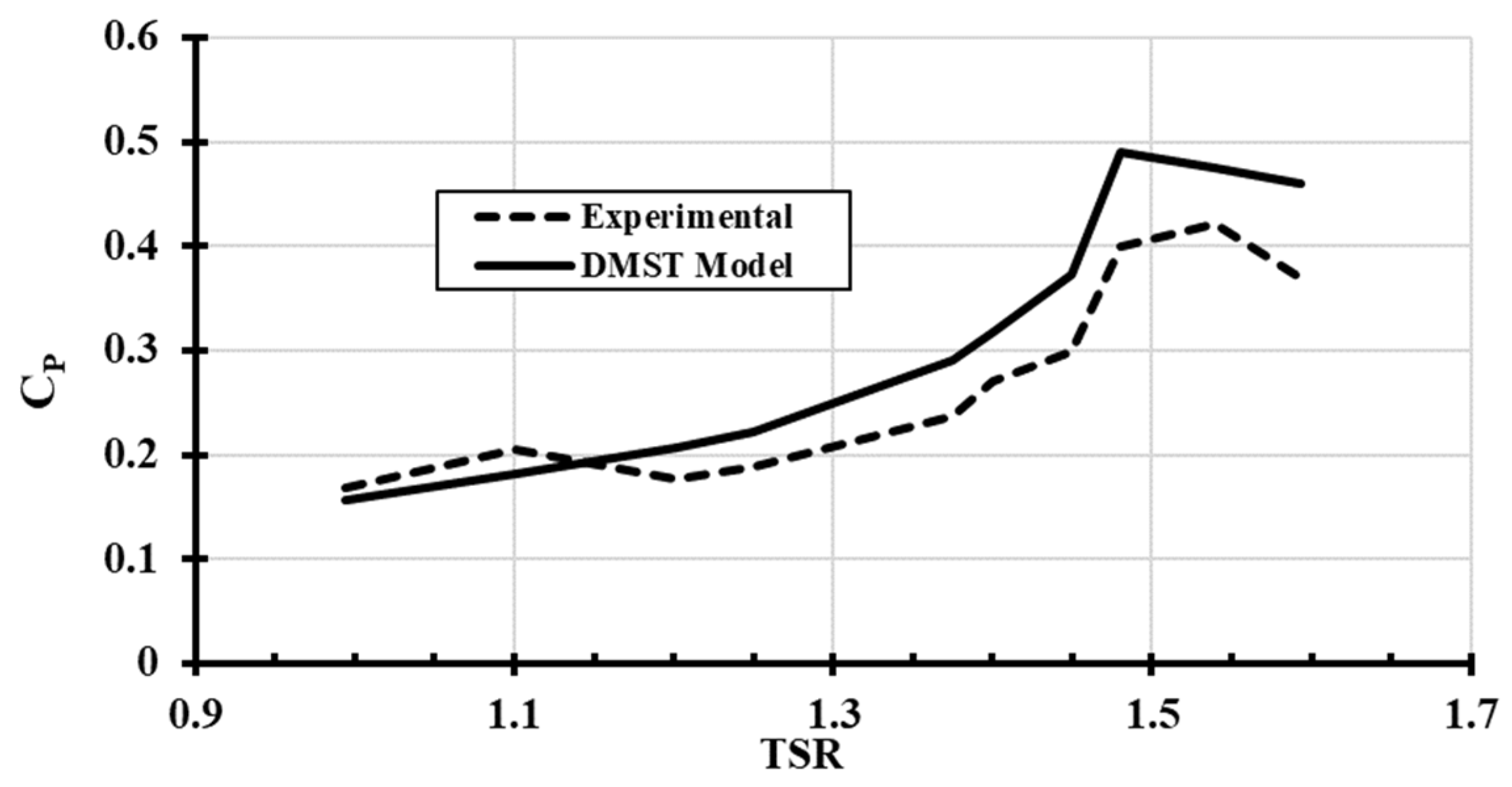
3.3. Experimental Validation

The blade pitch angle effect on H-type Darrieus VAWT performance will be investigated in this study in terms of overall power output, self-start ability, and overspeed control. A full-scale H-type Darrieus VAWT with blade pitching capability was built to validate the results obtained numerically. The blade pitch angle was adjusted manually by rotating the blade either clockwise (positive pitching) or counterclockwise (negative pitching). A step of 2.5° was applied in each run within a range between (β = −15°) and (β = 10°). The step size ensures precise adjustment during the experimentation. A torque meter was placed on the main shaft of the wind turbine to record the torque and the rotational speed at each run. The torque meter was connected to a data acquisition system that captured the desired readings every 0.5 s. Data were collected for multiple runs at different wind speeds ranging from 4 m/s to 13 m/s for each pitch angle within the mechanical pitching range. The experimental data collected were aligned with the numerical results found, showing similar trends in both numerical and experimental graphs, as presented in Figure 5, Figure 6 and Figure 7. This alignment confirms the accuracy of the numerical model used. Figure 5 and Figure 6 present the power coefficient (CP) changes at different wind speeds (VW) while applying different blade pitch angles (β). The dashed line represents the experimental results, which were compared to the theoretical results obtained using the DMST model.

4. Results and Discussion

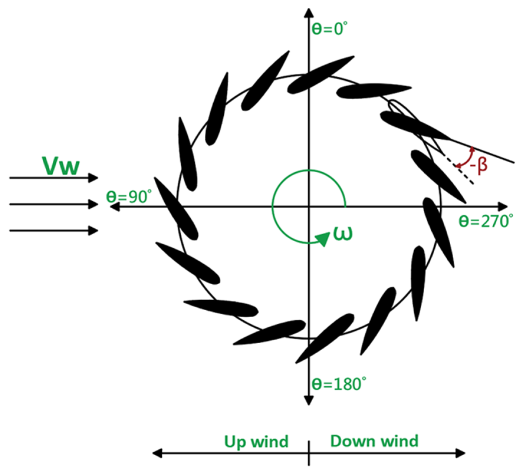
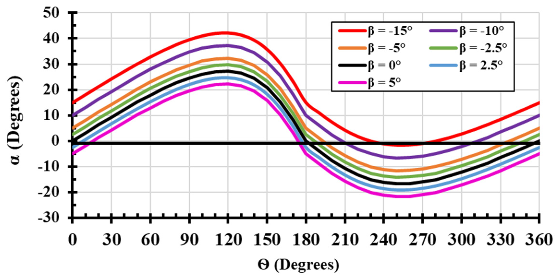
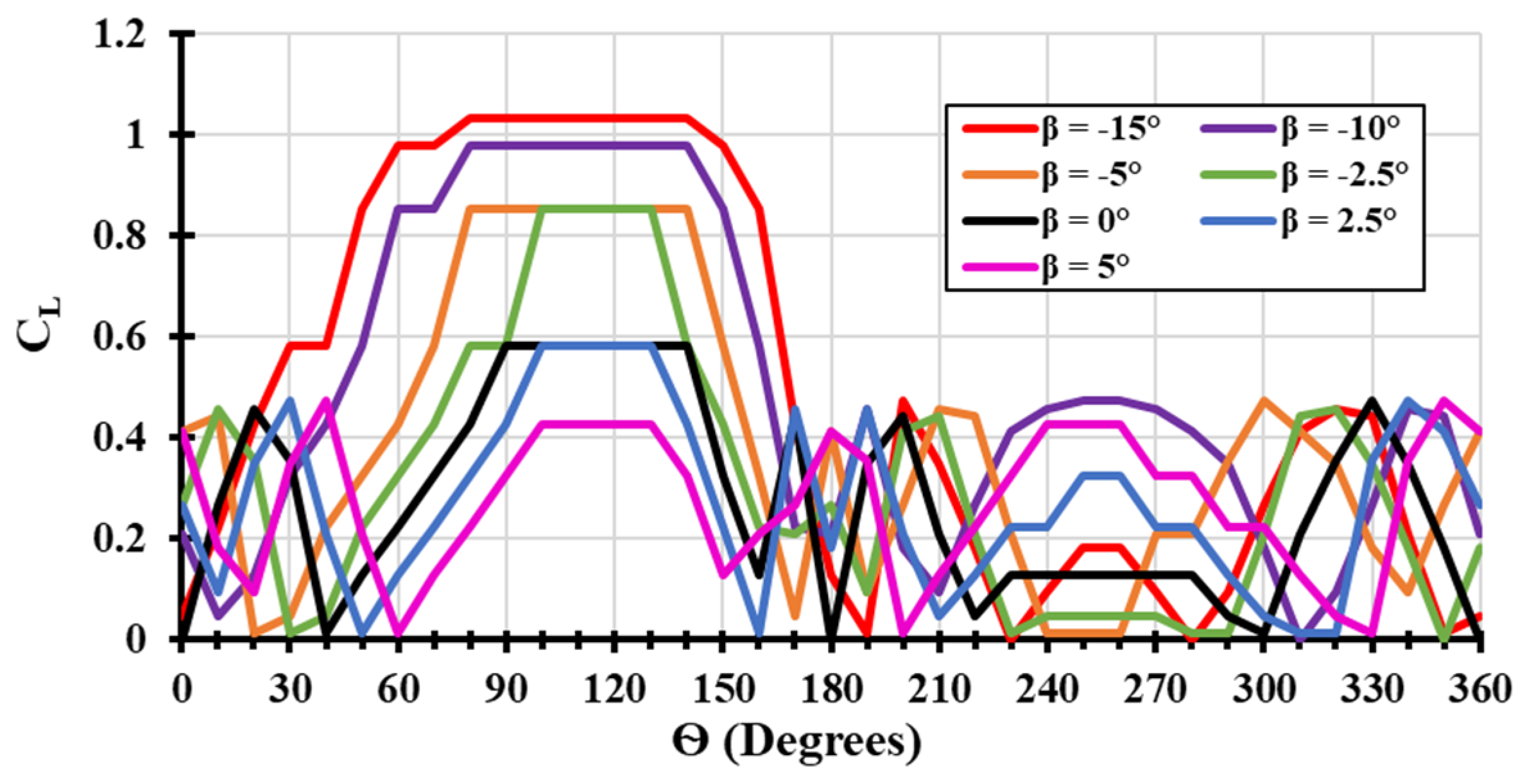
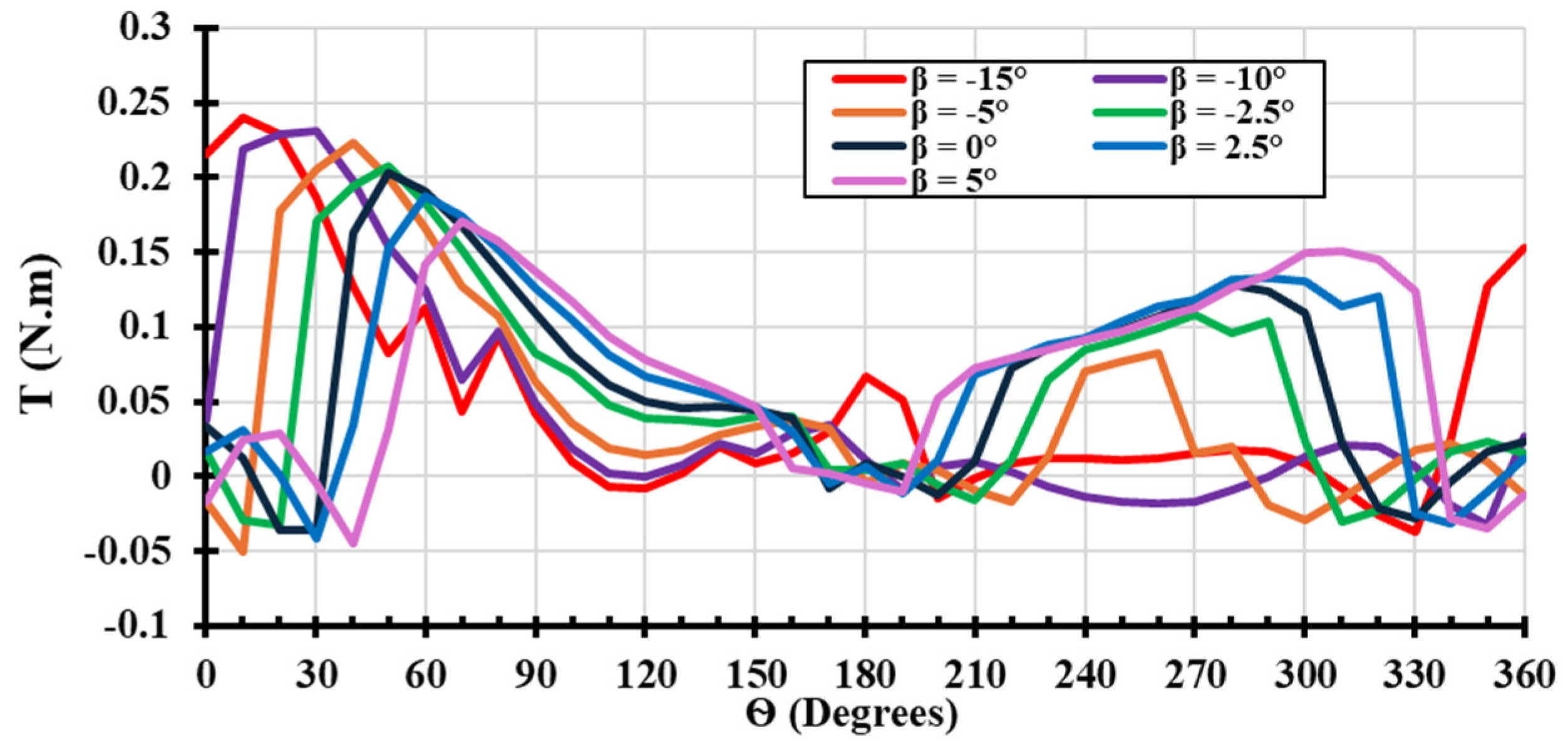
4.1. Impact of Blade Pitch Angle Regulation on H-Type Darrieus VAWT Aerodynamics

Fixed pitch angle adjustment involves rotating the blade by a fixed amount either towards the inside or outside of the rotor circle trajectory. This change directly affects the angle of attack (AOA), resulting in a negative or positive shift in the AOA value, as presented in Figure 8. Negative pitching increases the angle of attack value in the upstream region and reduces the AOA in the downstream region of the rotor. The change in AOA leads to significant aerodynamic changes, which can be useful in some operational conditions such as the starting stage.
The change in the AOA will result in changes in the lift coefficient and drag coefficient, as presented in Figure 9 and Figure 10, respectively. The highest coefficient of lift and drag are obtained at a pitch angle of (β = −15°) in the azimuth positions between 60° and 150°; the angle of attack is almost in the range between ( α = 35 ° ) and ( α = 45 ° ). At high angles of attack, the separated flow creates vortices that increase the lift forces, but at the same time, significantly increase the drag forces [37]. Additionally, AOA creates a considerable pressure difference across the blade, resulting in a higher lift force; however, the effectiveness of the lift force is reduced because of the separated flow, while the drag force increases [38]. At large angles of attack, a larger area of the blade surface is exposed to the airflow, which increases both the lift and drag [39].
Fixed blade pitching can increase the value of the torque peak during operation; however, this could reduce the torque generated at other azimuth positions, as illustrated in Figure 11. For instance, at a pitch angle of ( β = 15 ° ), the value of the torque reaches the peak at the range between ( θ = 0 ° ) and ( θ = 30 ° ) azimuth positions; then the torque reduces towards 180°. This occurs as a result of an aerodynamic stall due to the high angle of attack reached after the azimuth position of ( θ = 30 ° ). In the downstream part of the rotor, the torque generated at ( β = 15 ° ) was much less than the torque generated at ( β = 0 ° ). The torque (T) against the Azimuth angle ( θ ) graph in Figure 11 shows the individual contributions of each blade to the total torque of the H-type Darrieus VAWT at different pitch angles.

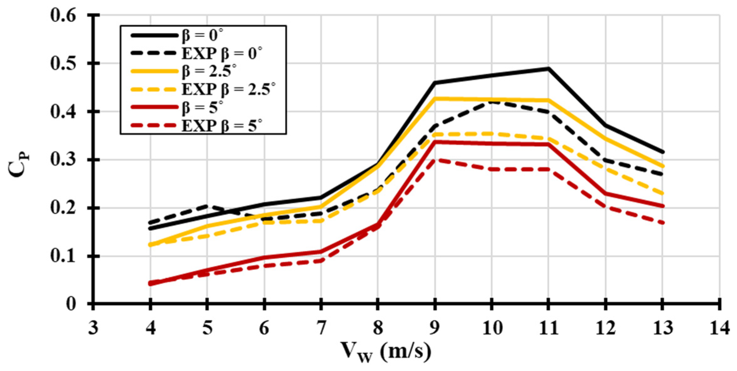
4.2. Effect of Blade Pitch Angle Regulation on H-Type Darrieus VAWT Performance

The numerical simulations were run with different positive and negative fixed pitch angle values to find the effect of the blade pitch angle on the torque generated. The optimum fixed pitch angle that can enhance the performance of the H-type Darrieus VAWT during various wind speeds will be examined. Figure 12 shows the power coefficient versus different wind speeds between ( V W = 4   m / s ) and ( V W = 13   m / s ) and at various pitch angles between ( β = 15 ° ) and ( β = 10 ° ). The data were taken in the turbine steady-state condition; therefore, the wind turbine’s ability to start is not considered in this part.
From Figure 12, it is obvious that any increase or decrease in the fixed blade pitch angle value between ( β = 15 ° ) and ( β = 10 ° ) will reduce the power coefficient of the wind turbine. The highest power coefficient occurs at a pitch angle equal to zero ( β = 0 ° ). The higher the pitch angle, either positive or negative, the less power is obtained. Even a small pitch angle which can delay the stall will have a negative effect on the rotor in the downstream region, as shown in Figure 11. Furthermore, the higher the pitch angle towards ( β = 15 ° ), the higher the torque peak; however, this increase in the torque will be followed by a stall, creating a heavy drag force on the wind turbine blade. This will eventually affect the total amount of torque generated by the blades, leading to less rotational speed. The effect of the blade pitch angle on the torque generated by each blade is represented as a radar graph in Figure 13. At a pitch angle of ( β = 0 ° ), the highest amount of accumulating torque is generated when compared to all other pitch angles. Figure 14 presents the effect of blade pitch angle of the rotational speed at different wind speed values.
The rotational speed (ω) at different pitch angle values and different wind speeds (VW) was obtained from the experimental testing for the H-type Darrieus VAWT. Increasing the fixed pitch angle in both positive and negative directions results in a reduction in the rotor’s rotational speed. This can be justified as more flow separation happens when a pitch angle is applied, leading to a higher drag force [40]. As presented in Figure 14, the highest rotational speed is reached at a zero pitch angle. The higher the pitch angle value, the lower the rotational speed obtained. This proves the ability of fixed blade pitch angle adjustment in controlling the excess speed reached by the wind turbine during high wind speed. Normally, the H-type Darrieus VAWT will have a cutoff wind speed. If the rotor reaches the cutoff speed, a brake mechanism will be used to reduce the rotational speed or stop the wind turbine [41]. By using fixed blade pitching, the wind turbine’s rotational speed can be controlled, consequently leading to a larger operational range within the turbine.

4.3. Self-Starting Behavior of H-Type Darrieus VAWT

H-type Darrieus VAWTs usually suffer from a low self-start ability [6]. This occurs due to low or even negative torque in some azimuth positions [16]. For the turbine to rotate, the torque generated at the beginning needs to overcome the inertia of the rotor. In most cases, if the wind turbine cannot start on its own, additional force needs to be added, either by using a starting mechanism or blade pitching [41]. In this section, we investigate enhancing the self-start ability of H-type Darrieus VAWTs through fixed blade pitching. At a zero pitch angle, the wind turbine is unable to start until the wind speed reaches ( V W = 9   m / s ). However, by using blade pitch angle regulation, the self-start ability of the turbine is improved, as presented in Table 2. The results in Table 2 were obtained experimentally. The test measured the minimum rotational speed required at a certain wind speed and pitch angle. The results show that as the blade pitch angle increases towards ( β = 15 ° ), which is the maximum range of blade pitching selected in this paper, the wind turbine’s ability to self-start improves. At a relatively low wind speed, for example, ( V W = 5   m / s ), the rotor will not have the ability to start due to low lift force; however, when the pitch angle is changed to ( β = 12.5 ° ), the turbine is able to rotate. The results of this study found that the initial rotational speed required for the H-type Darrieus VAWT is always lower when negative blade pitch adjustment is applied. Furthermore, negative fixed blade pitching can enhance the self-starting ability of H-type Darrieus VAWTs by up to 80%.

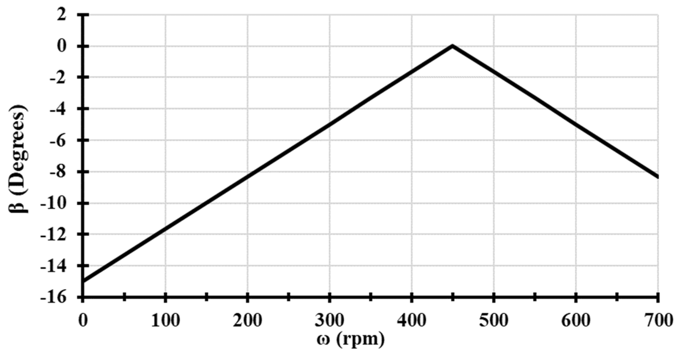
4.4. Hybrid Blade Pitch Angle Technique

Implementing variable pitch blade regulation in H-type Darrieus VAWTs faces several challenges. One primary obstacle is the mechanical complexity involved in designing and integrating a pitch control mechanism that can adjust the blade pitch dynamically. This complexity results in higher maintenance requirements and increases the risk of mechanical failure [42]. Additionally, the cost of manufacturing such a sophisticated system can be unaffordable, particularly for small-scale projects. Furthermore, the aerodynamic interactions of H-type Darrieus VAWTs are inherently complex [41,42], and adding a VP mechanism can further complicate the flow predictions, potentially leading to less turbine performance if not controlled precisely. This study proposes a hybrid blade pitching technique that uses fixed blade pitching, which can be varied based on the rotational speeds. This approach is particularly beneficial for improving the turbine’s self-starting ability and overspeed control. The new technique is mathematically represented by Equation (2).
β = ω ω I d e a l     β M a x   ω I d e a l
The equation considers the rotor rotational speed as the main factor. During the initial stage of turbine operation, where the rotational speed ( ω = 0 ), the pitch angle will be at the maximum. As demonstrated in Section 4.3, the higher the negative pitch angle towards ( β = 15 ° ), the better the self-start ability of the turbine. As the wind turbine reaches the ideal rotational speed for a specific wind speed value, the pitch angle is reduced towards a zero pitch ( β = 0 ° ). As mentioned in Section 4.2, the highest rotational speed value is achieved at a zero pitch angle. In the case of overspeed, the wind turbine blades will be pitched to a negative value as well to reduce the rotational speed by increasing the drag force acting on the blade. Similar to the starting stage, the blade pitch angle value will increase as the rotor reaches a higher excessive rotational speed. Figure 15 represents an example of the change in the pitch angle ( β ) as the wind turbine’s rotational speed increases for a selected wind speed of ( V W = 9   m / s ), with an ideal rotational speed which is set to ( ω I d e a l = 450   r p m ). The developed technique is less complicated on the aerodynamic side and is mechanically feasible to be implemented at a relatively lower cost compared to other VP techniques.

5. Conclusions

A hybrid blade pitching technique is introduced in this study to enhance the performance of H-type Darrieus VAWTs. The proposed novel technique combines variable and fixed blade pitch angle regulations to improve the starting and overspeed stages of turbine operations with reduced complexity. This technique was evaluated through both numerical and experimental investigations. Fixed pitching modifies the AOA across all azimuth positions by a constant value, altering the lift and drag coefficients, which in turn affects the torque and rotational speed. By applying negative blade pitching, the ability of the wind turbine to self-start increased, while positive pitching made it harder to start as it reduced the peak torque. Therefore, this study utilizes negative pitching to improve the starting and overspeed stages of H-type Darrieus VAWTs.
At the starting stage, negative pitching increases the turbine’s ability to self-start by nearly 80%, enabling operation at wind speeds of ( V W = 5   m / s ,   6   m / s ,   7   m / s ,   a n d   8   m / s ). Negative pitching also helps control excessive rotational speeds during high wind conditions by increasing the drag force. The proposed technique adjusts the blade pitch angle based on the rotational speed; at the initial start, the pitch angle is at its maximum value, and as the rotational speed increases toward the ideal situation, the blade pitching reduces toward a zero pitch angle ( β = 0 ° ). On the other hand, for an excessive rotational speed, the pitch angle increases as the rotational speed exceeds the rated value.
The hybrid method developed can also be applied to various types of lift-based wind turbines as it enhances self-starting capabilities by optimizing the interaction between the wind and the blades, enabling turbines to start more effectively under low wind conditions. This improvement is particularly beneficial for regions with variable wind speeds, where efficient self-starting is crucial. Furthermore, the hybrid method strategically employs aerodynamic forces to manage the rotational speed of the wind turbine during overspeed conditions. This feature ensures safe operation by preventing mechanical stress and potential damage while maintaining optimal performance by adapting to changes in wind conditions.

Author Contributions

Conceptualization, M.A.H. and A.M.M.; Methodology, M.A.H. and A.M.A.; Software, M.A.H. and S.S.; Validation, A.M.M. and A.M.A.; Formal analysis, M.A.H.; Investigation, S.S. and A.M.A.; Data curation, M.A.H.; Writing—original draft preparation, M.A.H.; Supervision, A.M.M., S.S. and A.M.A. All authors have read and agreed to the published version of the manuscript.

Funding

This research received no external funding.

Data Availability Statement

Data are contained within the article.

Conflicts of Interest

The authors declare no conflicts of interest.

Appendix A

In the DMST model, the velocities are considered by two induction factors, ( a ) and ( a ) . The upstream-induced velocity ( V i ) will be the average of the air velocity ( V W ) at the far upstream region and the air velocity at the downstream equilibrium ( V E ). For the first actuator disk, the induced velocity can be expressed as:
V i = V W + V E 2
V i = ( 1 a ) V W
( a ): induction factor at the upstream region.
The air velocity at the downstream equilibrium (VE) can be found using Equations (A1) and (A2):
V E = 2 V i V W = ( 1 2 a ) V W
The induced velocity at the downstream ( V i ) and the induction factor ( a ) at the downstream part of the wind turbine can be defined as:
V i = V E + V K 2
( V K ): velocity at far end of the rotor at the downstream region.
a = V E + V i V E
The induced velocity at the downstream ( V i ) region of the turbine can be identified using Equations (A3) and (A5):
V i = ( a 1 ) ( 1 2 a ) V W
The resultant velocity ( W ) and angle of attack ( α ) for the upstream part ( π / 2 θ 3 π / 2 ):
W = ( V i sin ( θ ) ) 2 + ( V i cos ( θ ) + ω R ) 2
( θ ) : azimuth angel, ( ω ) : angular velocity of the rotor, and ( R ) : rotor radius
α = t a n 1 ( 1 a ) sin θ 1 a cos θ + λ
( λ ): tip speed ratio.
For the downwind half ( 3 π / 2 θ π / 2 ):
W = ( V i sin ( θ ) ) 2 + ( V i cos ( θ ) + ω R ) 2
( W ): resultant velocity at the downstream part.
α = t a n 1 ( 1 a ) sin θ 1 a cos θ + λ
( α ): angle of attack at the downstream part.
Once the resultant velocity in the downstream ( W ) and the angle of attack in the downstream ( α ) are found using the downstream induction factor ( α ), the normal force coefficient and tangential force coefficient can be found for the upstream and downstream halves of the rotor:
C n = C L cos ( α ) + C D sin ( α )
( C n ): normal force coefficient at the upstream, ( C L ): lift force coefficient at the upstream, and ( C D ): drag force coefficient at the upstream.
C n = C L cos α + C D sin ( α )
( C n ): the normal force coefficient at the downstream, ( C L ): lift force coefficient at the downstream, and ( C D ) : drag force coefficient at the downstream.
C t = C L sin α C D cos ( α )
( C t ): tangential force coefficient at the upstream.
C t = C L sin α C D cos ( α )
( C t ): tangential force coefficient at the downstream.
The values for the lift coefficient ( C L ) and drag coefficient ( C D ) for the selected airfoil were determined based on data from Sandia National Laboratories [43], taking into account the angle of attack and the Reynolds number ( R e ):
R e = ρ W C μ
( ρ ): air density (1.225 kg/m3), ( C ): airfoil chord length, and ( μ ): dynamic air viscosity (1.81 × 10⁻⁵ kg/ms).
Normal force at the upstream ( F N ) , normal force at the downstream ( F N ) , tangential force at the upstream ( F T ) , and tangential force at the downstream ( F T ) for single blade at a particular azimuthal position can be presented as:
F N = 1 2 ρ W 2 ( H C ) C n
F T = 1 2 ρ W 2 ( H C ) C T
The instantaneous torque at the upstream ( T u p ) and at the downstream ( T d w ) by a single blade at a particular azimuthal position can be expressed by:
T u p = F T R
T d w = F T R
The instantaneous power output at the upstream ( P u p ) and the downstream ( P d w ) by a single blade at a particular azimuthal position can be found using:
P u p = T θ ω
P d w = T θ ω
The total wind turbine circular path is divided into multiple streamtubes, where each streamtube passes through the upstream and downstream part of the rotor. The fix angle of the streamtubes ( θ ) is calculated by:
θ = 2 π N θ
The average power output for the upstream ( P u p ) and the downstream ( P d w ) parts can be determined by taking the average power output for all streamtubes at each side separately:
P u p = N · 1 2 π · π 2 π P u p
( N ): is the number of blades.
P d w = N · 1 2 π · 0 π P d w
The power coefficient for the upstream ( C P u p ) and the downstream ( C P d w ) :
C P u p = P u p 0.5 ρ A V W 3
( A ): area of the blade.
C P d w = P d w 0.5 ρ A V W 3
Obtaining the total coefficient of power ( C P ) by adding the power coefficients at the upstream and the downstream:
C P = C P u p + C P d w

References

  1. Didane, D.H.; Behery, M.R.; Al-Ghriybah, M.; Manshoor, B. Recent Progress in Design and Performance Analysis of Vertical-Axis Wind Turbines—A Comprehensive Review. Processes 2024, 12, 1094. [Google Scholar] [CrossRef]
  2. Acosta-López, J.G.; Blasetti, A.P.; Lopez-Zamora, S.; de Lasa, H. CFD Modeling of an H-Type Darrieus VAWT under High Winds: The Vorticity Index and the Imminent Vortex Separation Condition. Processes 2023, 11, 644. [Google Scholar] [CrossRef]
  3. Zereg, A.; Aksas, M.; Bouzaher, M.T.; Laghrouche, S.; Lebaal, N. Efficiency Improvement of Darrieus Wind Turbine Using Oscillating Gurney Flap. Fluids 2024, 9, 150. [Google Scholar] [CrossRef]
  4. Abdalrahman, G.; Daoud, M.A.; Melek, W.W.; Lien, F.-S.; Yee, E. Design and Implementation of an Intelligent Blade Pitch Control System and Stability Analysis for a Small Darrieus Vertical-Axis Wind Turbine. Energies 2022, 15, 235. [Google Scholar] [CrossRef]
  5. Kumar, R.; Raahemifar, K.; Fung, A.S. A critical review of vertical axis wind turbines for urban applications. Renew. Sustain. Energy Rev. 2018, 89, 281–291. [Google Scholar] [CrossRef]
  6. Du, L.; Ingram, G.; Dominy, R.G. A review of H-Darrieus wind turbine aerodynamic research. Proc. Inst. Mech. Eng. Part C J. Mech. Eng. Sci. 2019, 233, 7590–7616. [Google Scholar] [CrossRef]
  7. Nizamani, Z.; Muhammad, A.; Ali, M.O.A.; Wahab, M.A.; Nakayama, A.; Ahmed, M.M. Renewable wind energy resources in offshore low wind speeds regions near the equator: A review. Ocean Eng. 2024, 311, 118834. [Google Scholar] [CrossRef]
  8. Gupta, A.; Abderrahmane, H.A.; Janajreh, I. Flow analysis and sensitivity study of vertical-axis wind turbine under variable pitching. Appl. Energy 2024, 358, 122648. [Google Scholar] [CrossRef]
  9. Sun, X.; Hao, T.; Zhang, J.; Dong, L.; Zhu, J. The performance increase of the wind-induced rotation VAWT by application of the passive variable pitching blade. Int. J. Low-Carbon Technol. 2022, 17, 1420–1434. [Google Scholar] [CrossRef]
  10. Zhao, Z.; Wang, R.; Shen, W.; Wang, T.; Xu, B.; Zheng, Y.; Qian, S. Variable pitch approach for performance improving of straight-bladed VAWT at rated tip speed ratio. Appl. Sci. 2018, 8, 957. [Google Scholar] [CrossRef]
  11. Yamada, T.; Kiwata, T.; Kita, T.; Hirai, M.; Komatsu, N.; Kono, T. Overspeed Control of a Variable-Pitch Vertical-Axis Wind Turbine by Means of Tail Vanes. J. Environ. Eng. 2012, 7, 39–52. [Google Scholar] [CrossRef]
  12. Miliket, T.A.; Ageze, M.B.; Tigabu, M.T. Aerodynamic performance enhancement and computational methods for H-Darrieus vertical axis wind turbines: Review. Int. J. Green Energy 2022, 19, 1428–1465. [Google Scholar] [CrossRef]
  13. Szczerba, Z.; Szczerba, P.; Szczerba, K.; Szumski, M.; Pytel, K. Wind Tunnel Experimental Study on the Efficiency of Vertical-Axis Wind Turbines via Analysis of Blade Pitch Angle Influence. Energies 2023, 16, 4903. [Google Scholar] [CrossRef]
  14. Hao, W.; Abdi, A.; Wang, G.; Wu, F. Study on the Pitch Angle Effect on the Power Coefficient and Blade Fatigue Load of a Vertical Axis Wind Turbine. Energies 2023, 16, 7279. [Google Scholar] [CrossRef]
  15. Castillo, O.C.; Andrade, V.R.; Rivas, J.J.R.; González, R.O. Comparison of Power Coefficients in Wind Turbines Considering the Tip Speed Ratio and Blade Pitch Angle. Energies 2023, 16, 2774. [Google Scholar] [CrossRef]
  16. Sagharichi, A.; Maghrebi, M.J.; ArabGolarcheh, A. Variable pitch blades: An approach for improving performance of Darrieus wind turbine. J. Renew. Sustain. Energy 2016, 8, 053305. [Google Scholar] [CrossRef]
  17. Liu, L.; Liu, C.; Zheng, X. Modeling, simulation, hardware implementation of a novel variable pitch control for H-type vertical axis wind turbine. J. Electr. Eng. 2015, 66, 264–269. [Google Scholar] [CrossRef]
  18. Zhao, Z.; Qian, S.; Shen, W.; Wang, T.; Xu, B.; Zheng, Y.; Wang, R. Study on variable pitch strategy in H-type wind turbine considering effect of small angle of attack. J. Renew. Sustain. Energy 2017, 9, 053302. [Google Scholar] [CrossRef]
  19. Arif, S.K.; Maree, I.E. Investigation on aerodynamic performance of H-type darrieus vertical axis wind turbine with different series airfoil shapes. Al-Qadisiyah J. Eng. Sci. 2023, 16, 121–126. [Google Scholar] [CrossRef]
  20. Islam, M.; Ting, D.S.-K.; Fartaj, A. Aerodynamic models for Darrieus-type straight-bladed vertical axis wind turbines. Renew. Sustain. Energy Rev. 2008, 12, 1087–1109. [Google Scholar] [CrossRef]
  21. Moutis, P.; Pastromas, S.; Hatziargyriou, N.D. Load-frequency control supported by variable speed variable pitch wind generators—From theory to testing. Eur. Wind Energy Conf. Exhib. EWEC 2013, 3, 1743–1748. [Google Scholar]
  22. Chougule, P.; Nielsen, S. Overview and Design of self-acting pitch control mechanism for vertical axis wind turbine using multi body simulation approach. J. Phys. Conf. Ser. 2014, 524, 012055. [Google Scholar] [CrossRef]
  23. Schönborn, A.; Chantzidakis, M. Development of a hydraulic control mechanism for cyclic pitch marine current turbines. Renew. Energy 2007, 32, 662–679. [Google Scholar] [CrossRef]
  24. Abdalrahman, G.; Melek, W.; Lien, F.-S. Pitch angle control for a small-scale Darrieus vertical axis wind turbine with straight blades (H-Type VAWT). Renew. Energy 2017, 114, 1353–1362. [Google Scholar] [CrossRef]
  25. Zhang, L.-X.; Liang, Y.-B.; Liu, X.-H.; Guo, J. Effect of blade pitch angle on aerodynamic performance of straight-bladed vertical axis wind turbine. J. Cent. South Univ. 2014, 21, 1417–1427. [Google Scholar] [CrossRef]
  26. Rezaeiha, A.; Kalkman, I.; Blocken, B. Effect of pitch angle on power performance and aerodynamics of a vertical axis wind turbine. Appl. Energy 2017, 197, 132–150. [Google Scholar] [CrossRef]
  27. Yang, Y.; Guo, Z.; Song, Q.; Zhang, Y.; Li, Q. Effect of blade pitch angle on the aerodynamic characteristics of a straight-bladed vertical axis wind turbine based on experiments and simulations. Energies 2018, 11, 1514. [Google Scholar] [CrossRef]
  28. Firdaus, R.; Kiwata, T.; Kono, T.; Nagao, K. Numerical and experimental studies of a small vertical-axis wind turbine with variable-pitch straight blades. J. Fluid Sci. Technol. 2015, 10, JFST0001. [Google Scholar] [CrossRef]
  29. Gerrie, C.; Islam, S.Z.; Gerrie, S.; Turner, N.; Asim, T. 3D CFD Modelling of Performance of a Vertical Axis Turbine. Energies 2023, 16, 1144. [Google Scholar] [CrossRef]
  30. Luo, Z.; Sun, Z.; Ma, F.; Qin, Y.; Ma, S. Power optimization for wind turbines based on stacking model and pitch angle adjustment. Energies 2020, 13, 4158. [Google Scholar] [CrossRef]
  31. Sarkar, R.; Julai, S.; Tong, C.W.; Uddin, M.; Romlie, M.; Shafiullah, G. Hybrid pitch angle controller approaches for stable wind turbine power under variable wind speed. Energies 2020, 13, 3622. [Google Scholar] [CrossRef]
  32. Templin, R.J. Aerodynamic Performance Theory for the NRC Vertical-Axis Wind Turbine; NASA STI/Recon Technical Report N76; National Aeronautical Establishment: Ottawa, ON, Canada, 1974. [Google Scholar]
  33. Wilson, R.E. LPBS, Machines Power Wind of Aerodynamics, Ntis Pb 238594; Oregon State University: Corvallis, OR, USA, 1974. [Google Scholar]
  34. Strickland, J.H. Darrieus Turbine: A Performance Prediction Model Using Multiple Streamtubes; Sandia Labs.: Albuquerque, NM, USA, 1975. [Google Scholar]
  35. Paraschivoiu, I.; Fraunie, P.; Beguier, C. Streamtube expansion effects on the Darrieus wind turbine. J. Propuls. Power 1985, 1, 150–155. [Google Scholar] [CrossRef]
  36. Pawsey, N. Development and Evaluation of Passive Variable-Pitch Vertical Axis Wind Turbines. Ph.D. Thesis, The University of New South Wales, Sydney, NSW, Australia, 2002. [Google Scholar]
  37. Shahriar, A.; Kumar, R.; Shoele, K. Vortex dynamics of axisymmetric cones at high angles of attack. Theor. Comput. Fluid Dyn. 2023, 37, 337–356. [Google Scholar] [CrossRef]
  38. Faure, T.M.; Leogrande, C. High angle-of-attack aerodynamics of a straight wing with finite span using a discrete vortex method. Phys. Fluids 2020, 32, 104109. [Google Scholar] [CrossRef]
  39. Sogukpinar, H. The effects of NACA 0012 airfoil modification on aerodynamic performance improvement and obtaining high lift coefficient and post-stall airfoil. AIP Conf. Proc. 2018, 1935, 020001. [Google Scholar]
  40. Hansen, M.O.L. Aerodynamics of Wind Turbines, 2nd ed.; Earthscan: London, UK, 2008. [Google Scholar]
  41. Torabi, F. Fundamentals of Wind Farm Aerodynamic Layout Design; Academic Press: Cambridge, MA, USA, 2022. [Google Scholar]
  42. Battisti, L. Design Options to Improve the Dynamic Behavior and the Control of Small H-Darrieus VAWTs. Appl. Sci. 2021, 11, 9222. [Google Scholar] [CrossRef]
  43. Robert, S.E.; Paul, K.C. Aerodynamic Characteristics of Seven Symmetrical Airfoil Sections through 180-Degree Angle of Attack for Use in Aerodynamic Analysis of Vertical Axis Wind Turbines. Sandia National Lab.: Albuquerque, NM, USA, 1981. [Google Scholar] [CrossRef]
Figure 1. Schematic representation of blade pitch for H-type Darrieus VAWT.
Energies 17 04044 g001
Figure 2. Proposed blade pitch angle technique.
Energies 17 04044 g002
Figure 3. Illustration of two actuator disks used in DMST. (Vi) is the induced velocity at the upstream part of the wind turbine, (VE) is the air velocity at the equilibrium, (Vi′) is the induced velocity in the downstream region, and (VK′) is the velocity at far end of the rotor at the downstream region.
Energies 17 04044 g003
Figure 4. Numerical model flow chart for H-type Darrieus VAWT.
Energies 17 04044 g004
Figure 5. Validation of DMST model (VW−CP) curve at different negative pitch angles (β).
Energies 17 04044 g005
Figure 6. Validation of DMST model (VW−CP) curve at different positive pitch angles (β).
Energies 17 04044 g006
Figure 7. Validation of DMST model (TSR−CP) curve at pitch angle (β = 0°).
Energies 17 04044 g007
Figure 8. Variation of (Ѳ−AOA) at different pitch angles (β).
Energies 17 04044 g008
Figure 9. Variation of (Ѳ−CL) curve at different pitch angles (β).
Energies 17 04044 g009
Figure 10. Variation of (Ѳ−CD) curve at different pitch angles (β).
Energies 17 04044 g010
Figure 11. Variation of (Ѳ−T) curve at different pitch angles (β).
Energies 17 04044 g011
Figure 12. Variation of (VW−CP) curve at different pitch angles (β).
Energies 17 04044 g012
Figure 13. Torque (N·m) versus Azimuth angle (Degrees) at different blade pitch angles: (a) β = −10°, (b) β = −5°, (c) β = 0°, and (d) β = 5°.
Energies 17 04044 g013
Figure 14. Variation of (β−ω) curve at different wind speeds (VW).
Energies 17 04044 g014
Figure 15. Example of proposed technique variation of Pitch Angle (β) at different Rotational Speeds (ω).
Energies 17 04044 g015
Table 1. Rotor specifications for H-type Darrieus VAWT.
H-Type Darrieus VAWT SpecificationSymbolValue
Blade Profile------NACA0018
Blade Shape------Straight
Number of bladesN3
Rotor Radius (mm)R300
Blade height (mm)H400
Chord length (mm)C250
Solidityσ0.191
Table 2. Initial Rotational Speed (rpm) required for the H-type Darrieus VAWT to start.
VWβ = −15°β = −12.5°β = −10°β = −7.5°β = −5°β = −2.5°β = 0°β = 2.5°β = 5°β = 7.5°
4 m/sF-SF-SF-SF-SF-S100110110120F-S
5 m/s002030708090110110120
6 m/s0000205060100110120
7 m/s000010606090100120
8 m/s0000002080100110
9 m/s000000000110
10 m/s000000000110
11 m/s000000000110
12 m/s000000000100
13 m/s000000000100
(F-S): wind turbine failed to start even with the external support. (0): wind turbine is able to start without any external support.
Disclaimer/Publisher’s Note: The statements, opinions and data contained in all publications are solely those of the individual author(s) and contributor(s) and not of MDPI and/or the editor(s). MDPI and/or the editor(s) disclaim responsibility for any injury to people or property resulting from any ideas, methods, instructions or products referred to in the content.

