
Insights on Blackstart Provisioning Using a Synchronous Generator and Grid-Forming Inverter Using EMT Simulations

 , ,
, ,
Abstract
:1. Introduction
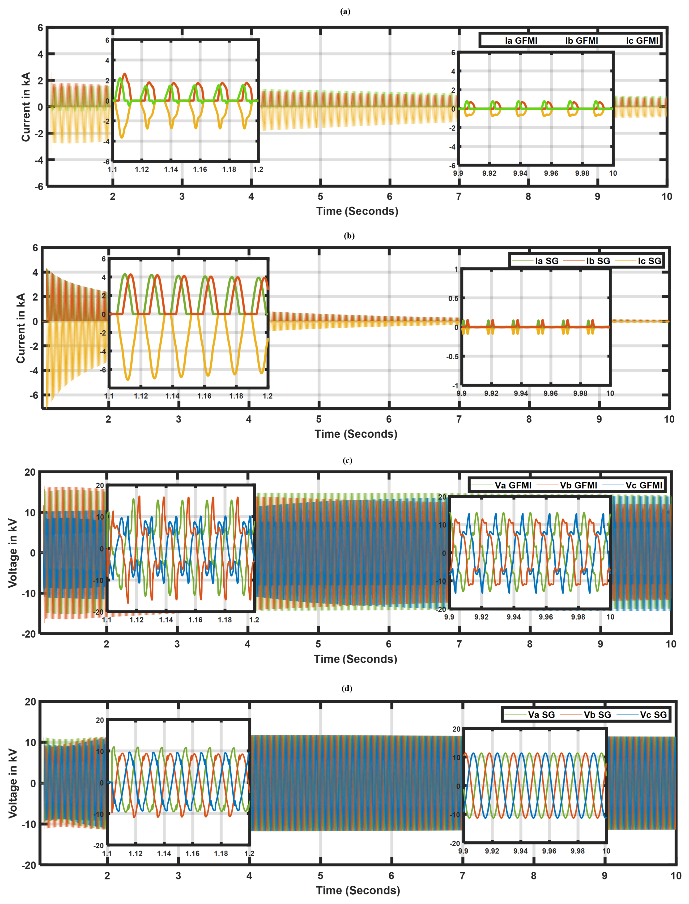
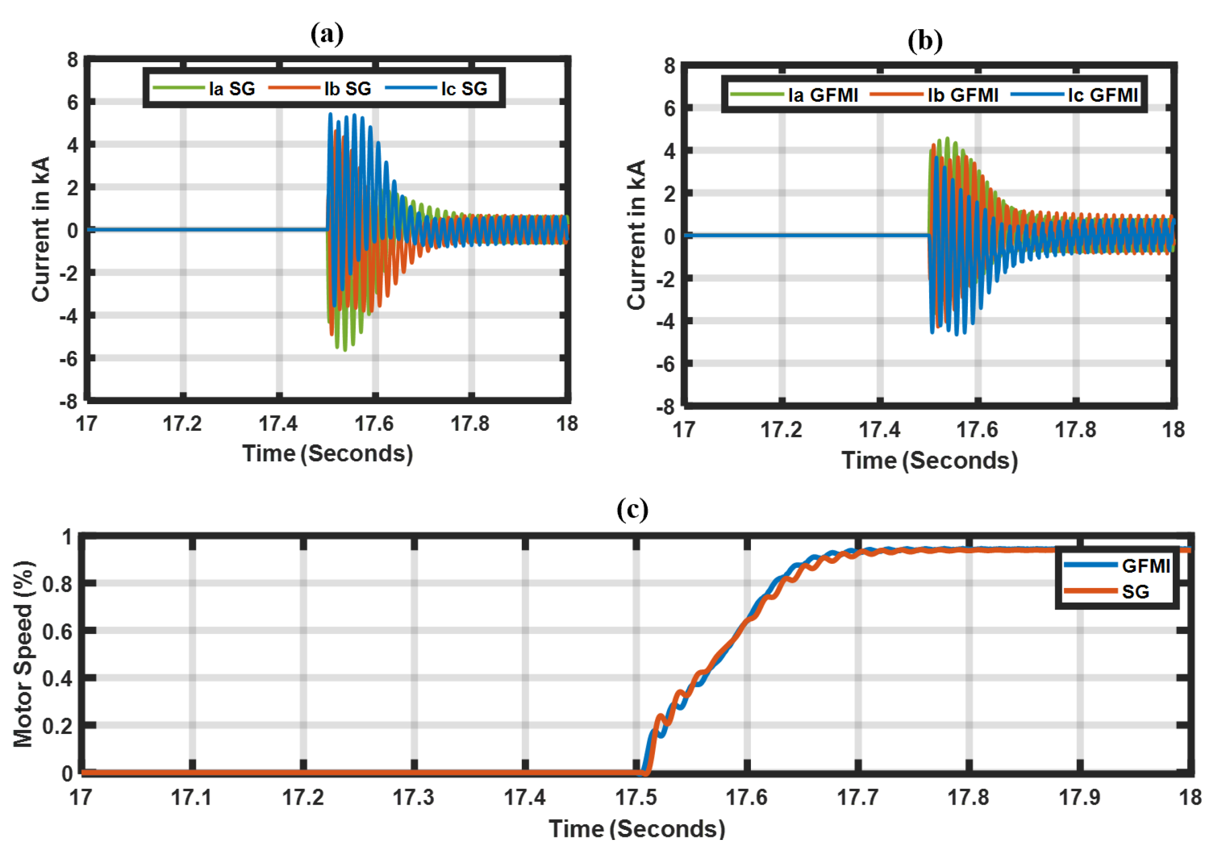
- A detailed study comparison between a GFMI and a conventional SG during a blackstart: Transformer and rotational motor load energization sequences were evaluated in detail; as a result, the findings reveal differences between the GFMI and SG. Nonetheless, the studies demonstrate that the GFMI can blackstart a bulk power system using conventional hard energization switching methods. (Section 3 and Section 4).
- Evaluation of the current-limiting schemes: These schemes are employed to protect the power inverter from the large inrush currents during the transformer and rotational motor load energization sequences. Furthermore, our investigations revealed that this current-limiting scheme behaves similarly to the SE method, which is executed by modifying the references of the GFMI. (Section 3).
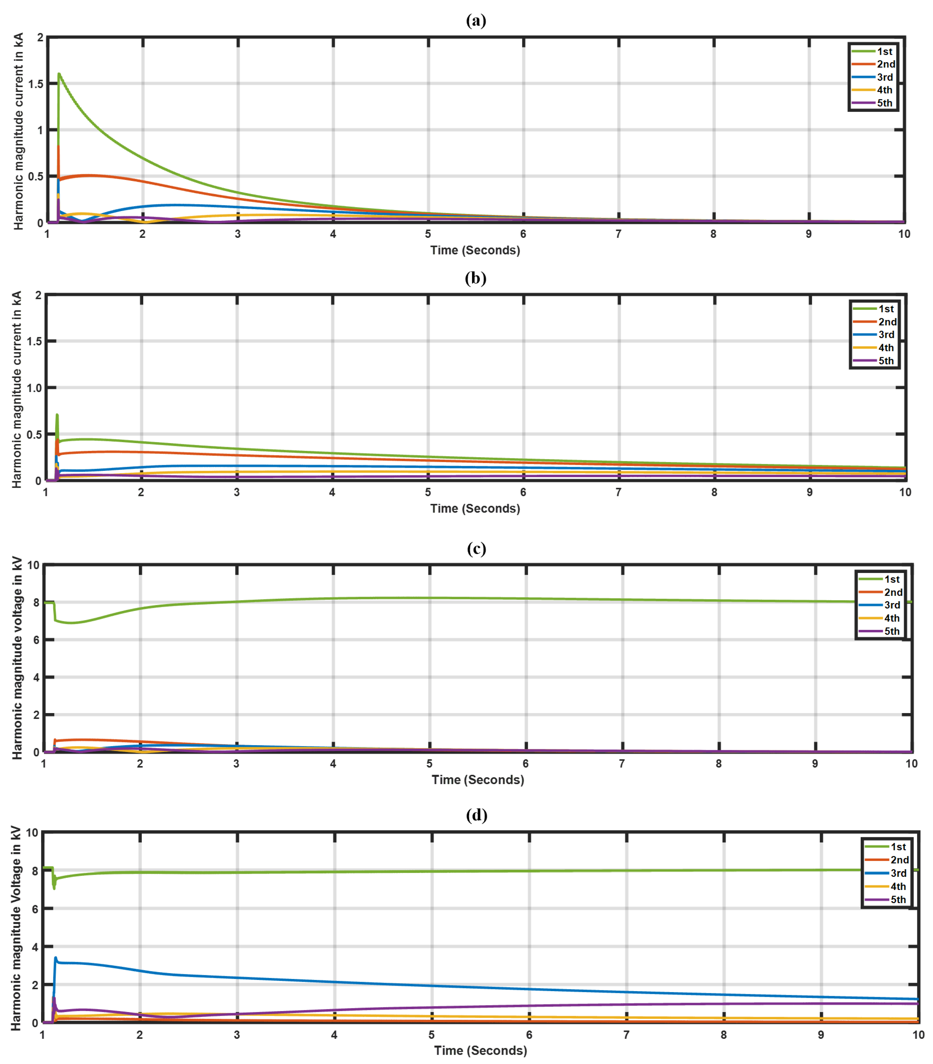
- Investigation of voltage and current harmonic distortions: The results demonstrated that the sympathetic interaction between the inverter’s medium voltage (MV) and plant step-up transformer generates extended inrush currents and over-voltages, resulting in higher harmonic distortions, which may require the protection relays to be adjusted. (Section 3).
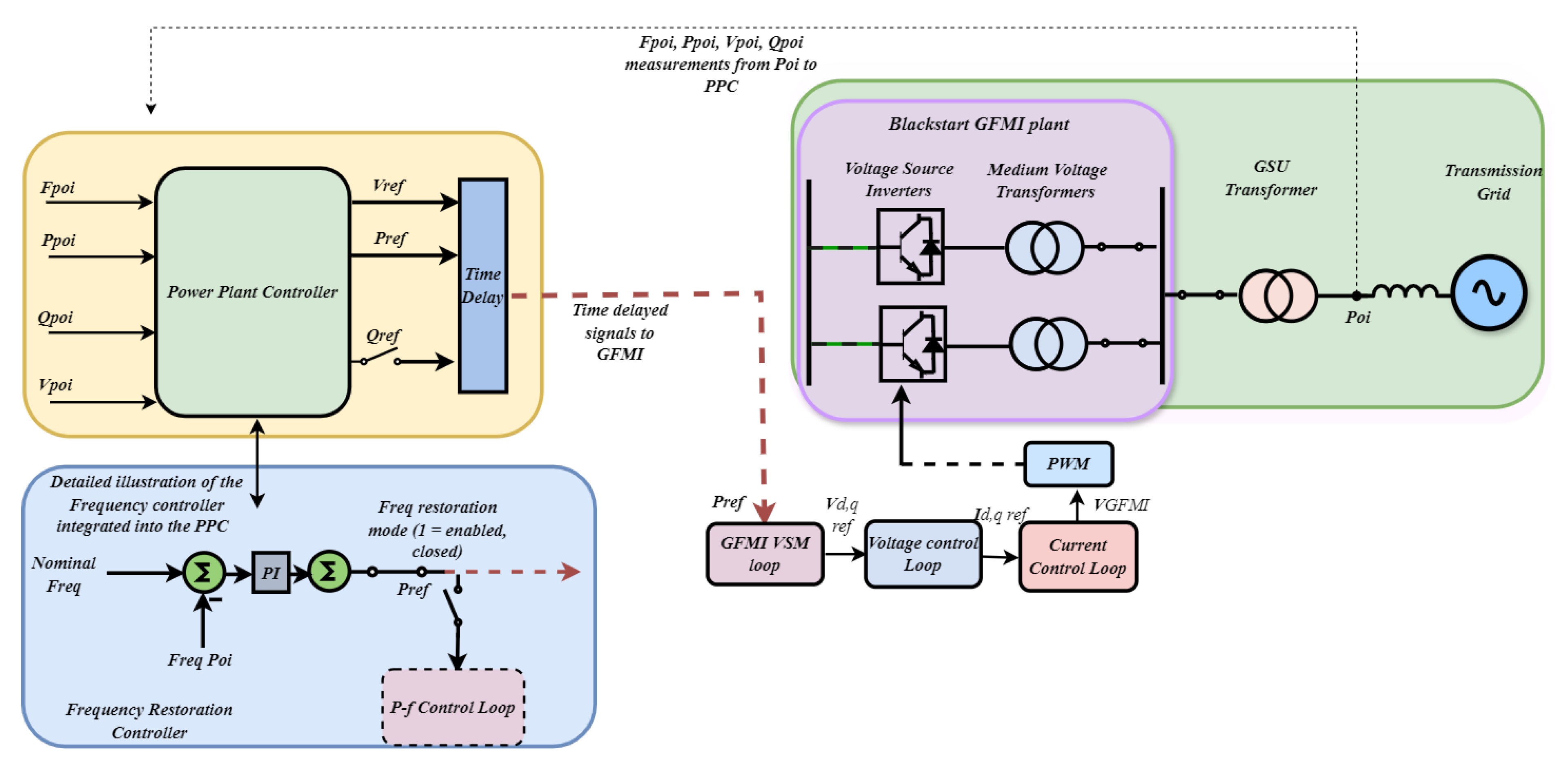
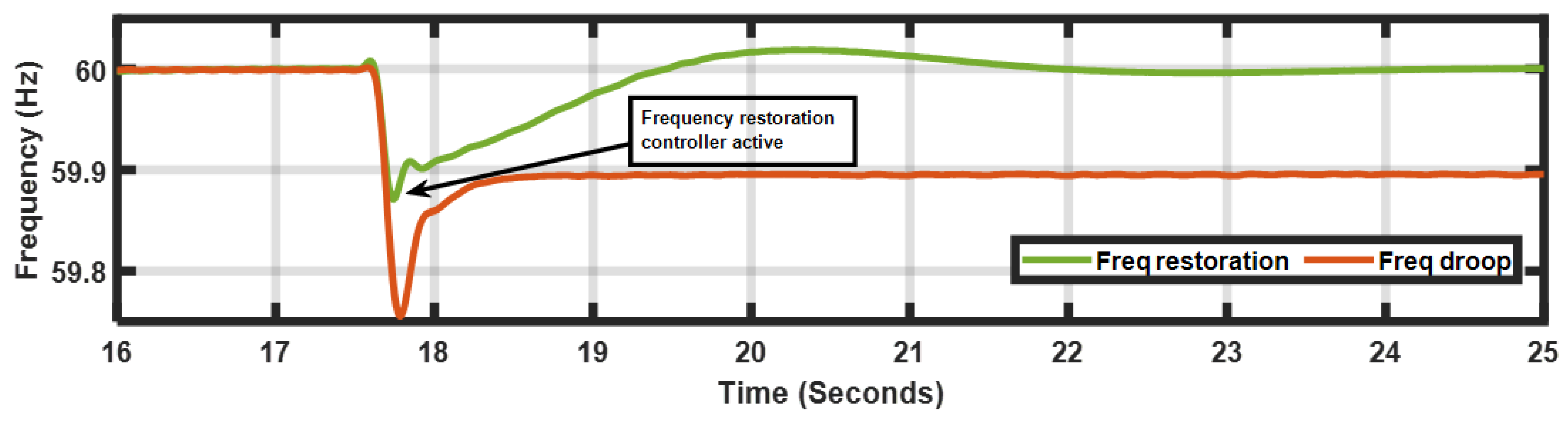
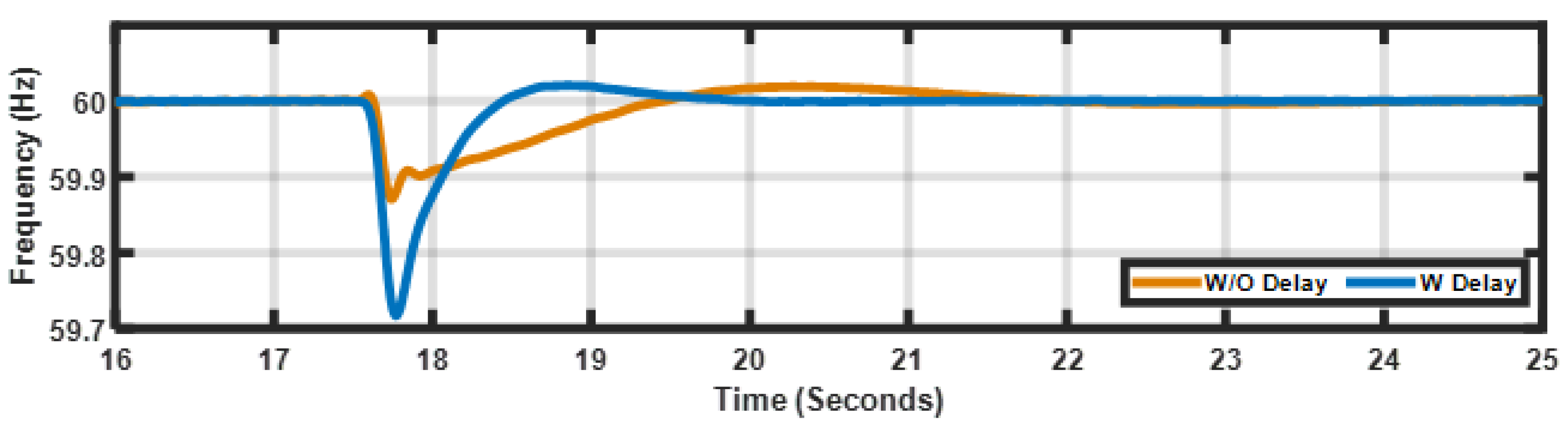
- Proposing an alternative method of restoring frequency after load pick-up by integrating a closed-loop controller in a power plant controller module (PPC). This method is beneficial, since it eliminates inverter-level control modifications. Communication delays between the PPC and inverter are also considered. (Section 4).
2. Blackstarting Concepts
2.1. Blackstart Synchronous Generator
2.2. Transformer Energization Sequence
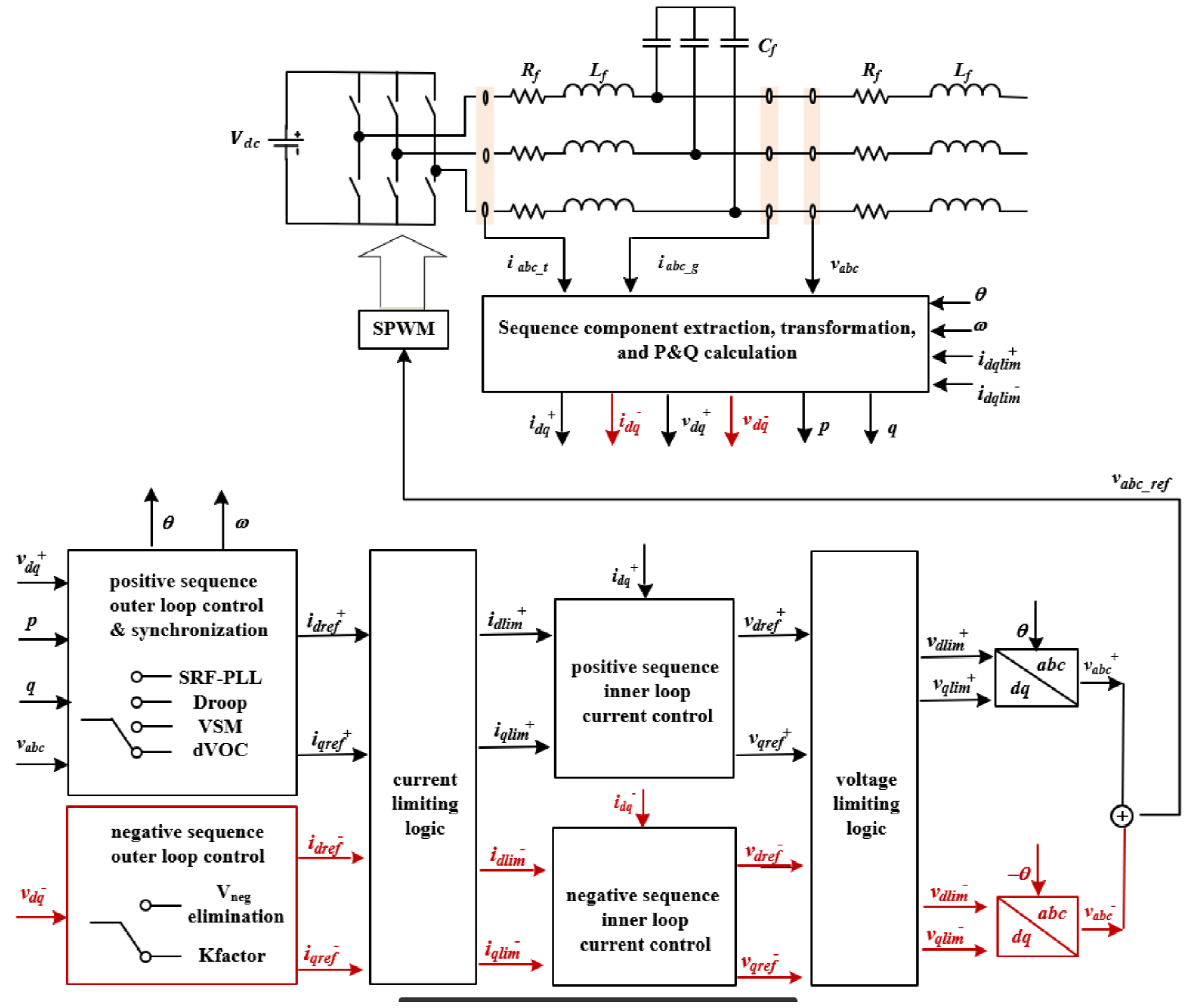
2.3. Grid-Forming Inverter Model
3. Comparative Network Case Studies
3.1. Study Assumptions and Methods
3.2. Transformer Energization Transients
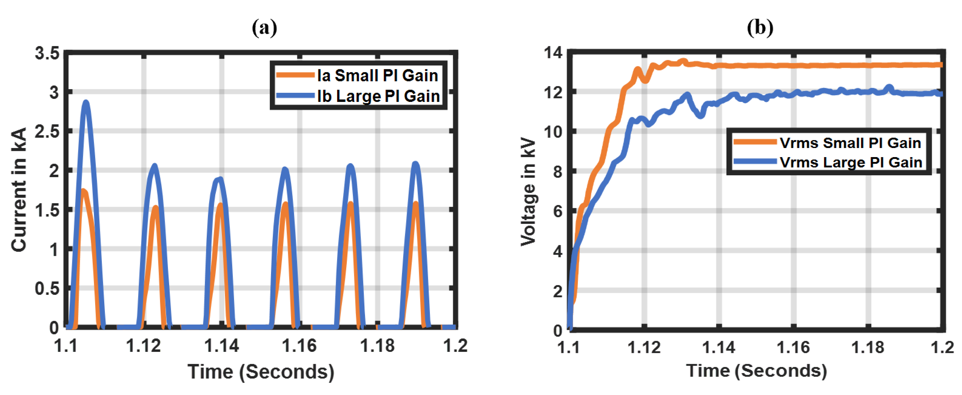
3.3. Impact of Voltage Loop Compensator Gains on Transformer Inrush
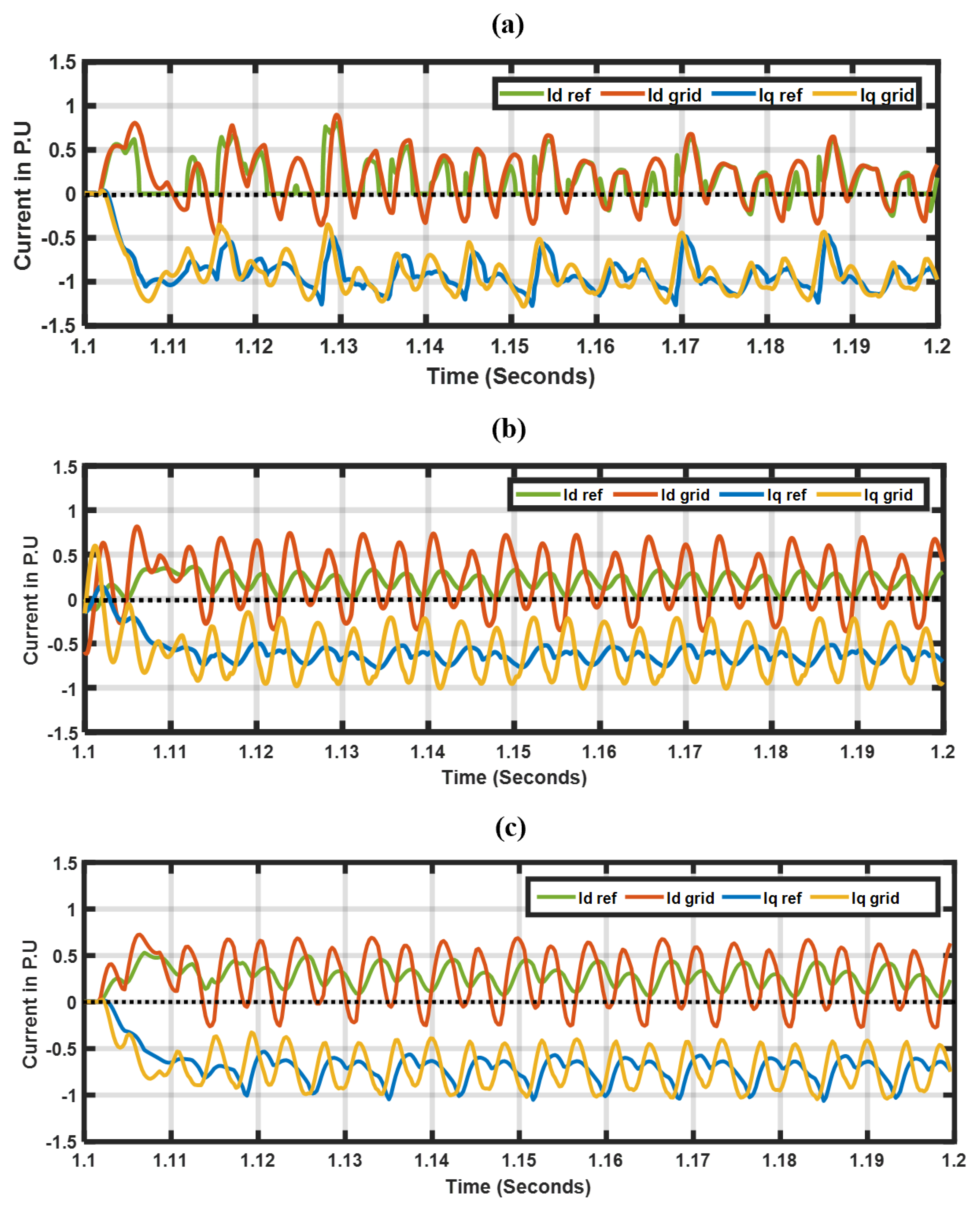
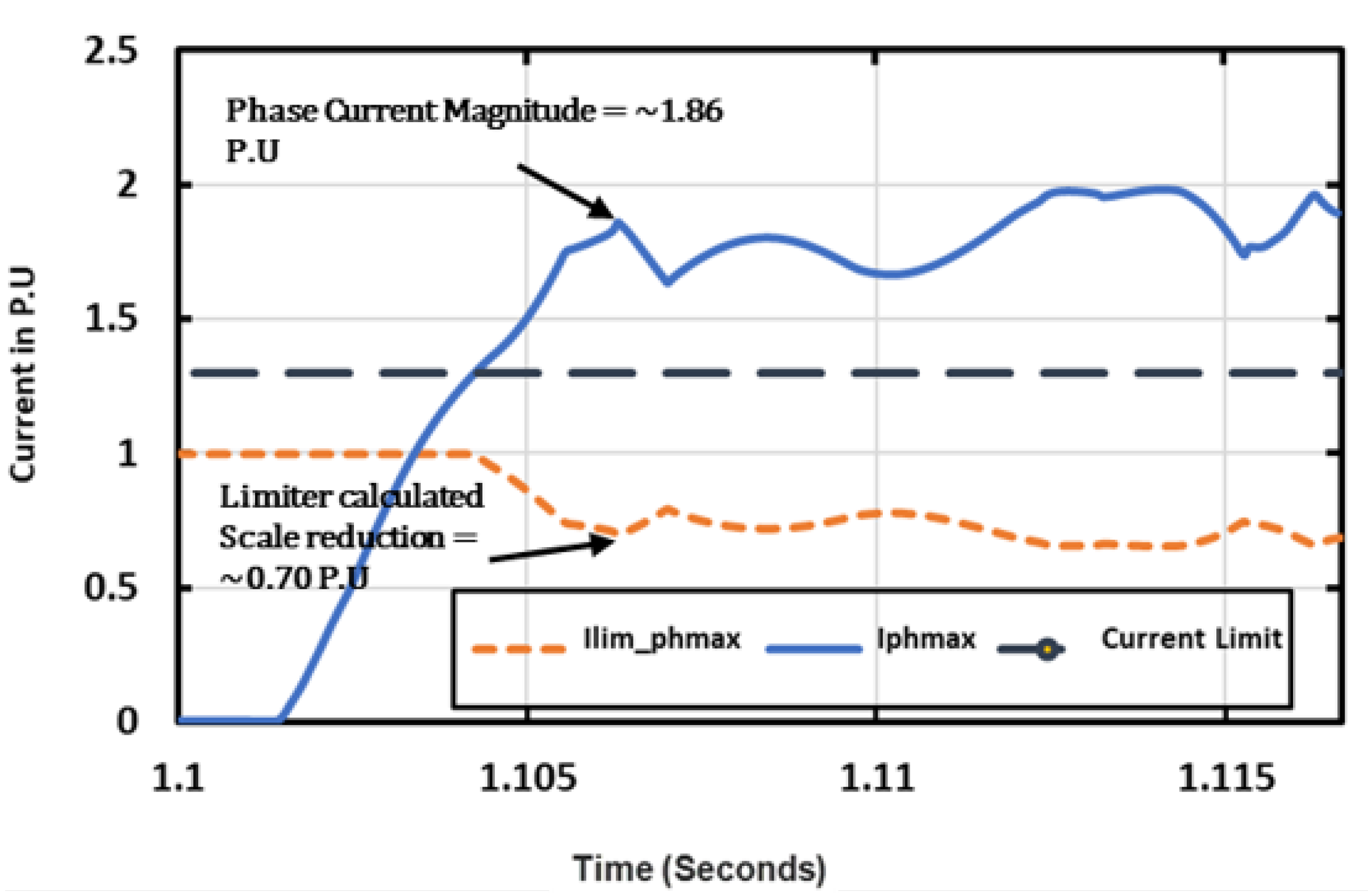
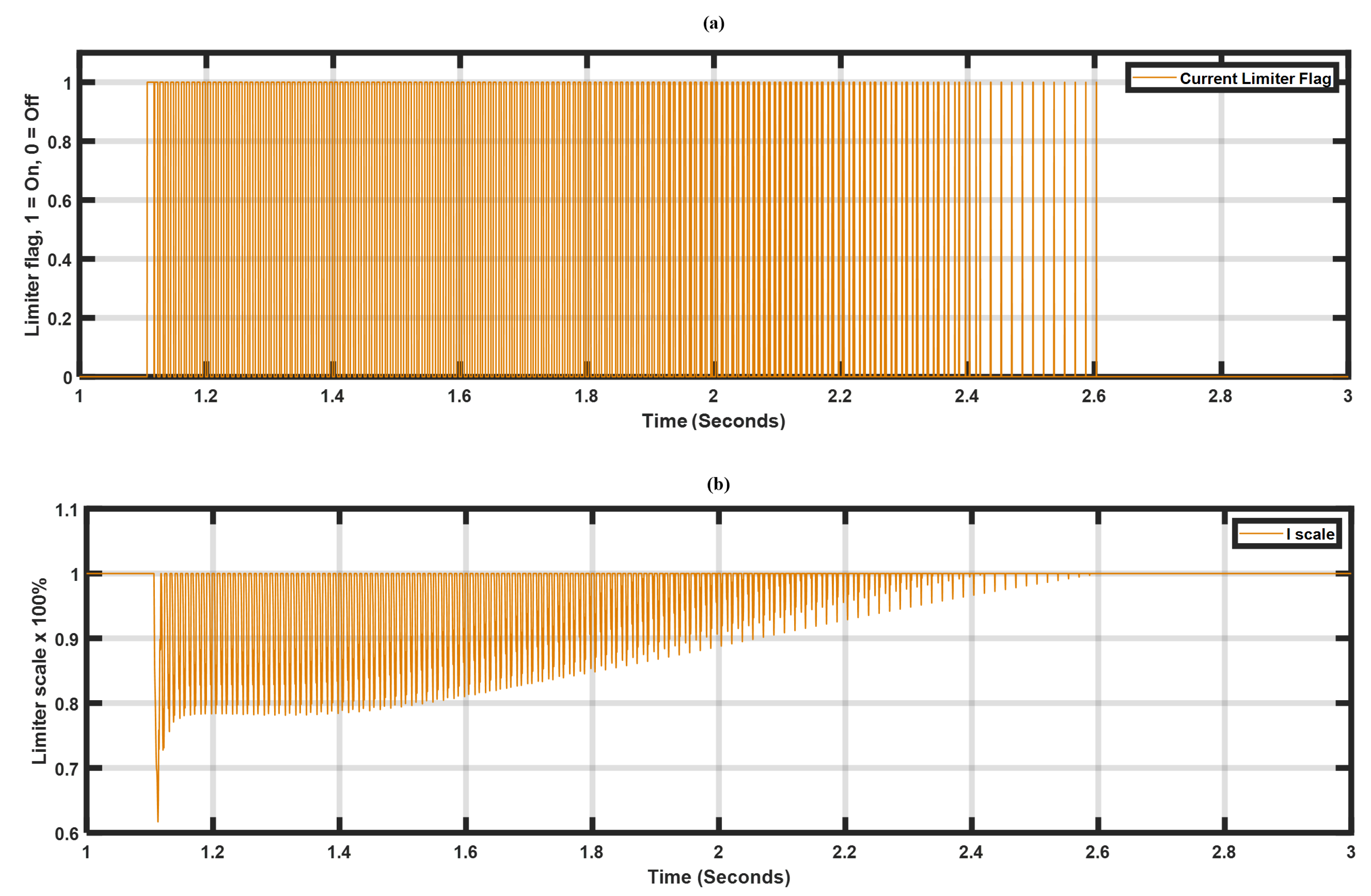
3.4. Impact of Inverter’s Current-Limiting Scheme on Transformer Inrush Currents
3.5. Harmonic Distortions from Transformer Energization
4. Motor Starting Transients
Proposed Frequency Restoration Using Power Plant Controller
5. Full Cranking Path Energization Results
6. Discussion
7. Conclusions and Future Work
- A detailed study comparison between a GFMI and a conventional SG during a blackstart: Transformer and rotational motor load energization sequences were evaluated in detail, as a result, the findings reveal differences between the GFMI and SG; nonetheless, the studies demonstrate that the GFMI can blackstart a bulk power system using conventional hard-energization switching methods.
- Evaluation of the current-limiting schemes: These schemes are employed to protect the power inverter from the large inrush currents during the transformer and rotational motor load energization sequences. Furthermore, our investigations revealed that this current-limiting scheme behaves similarly to the SE method, which is executed by modifying the references of the GFMI. The findings provided in [13] support our observations.
- Investigation of voltage and current harmonic distortions: The results demonstrated that the sympathetic interaction between the inverter’s medium voltage (MV) and plant step-up transformer generates extended inrush currents and over-voltages resulting in higher harmonic distortions, which may require the protection relays to be adjusted.
- Proposing an alternative method of restoring frequency after load pick-up by integrating a closed-loop controller in a power plant controller module (PPC). This method is beneficial because it eliminates inverter-level control modifications. Communication delays between the PPC and inverter are also considered.
Author Contributions
Funding
Data Availability Statement
Conflicts of Interest
References
- Rathnayake, D.B.; Akrami, M.; Phurailatpam, C.; Me, S.P.; Hadavi, S.; Jayasinghe, G.; Zabihi, S.; Bahrani, B. Grid Forming Inverter Modeling, Control, and Applications. IEEE Access 2021, 9, 114781–114807. [Google Scholar] [CrossRef]
- Schöley, A.; Jeinsch, T. Stability Investigation of PLL-Based Grid Synchronization. In Proceedings of the 2021 25th International Conference on Methods and Models in Automation and Robotics (MMAR), Międzyzdroje, Poland, 23–26 August 2021; pp. 233–238. [Google Scholar] [CrossRef]
- Special consideration in power system restoration. The second working group report. IEEE Trans. Power Syst. 1994, 9, 15–21. [CrossRef]
- Grid Forming Inverters: EPRI Tutorial (2023); Report 3002028090; EPRI: Palo Alto, CA, USA, 2023.
- Program on Technology Innovation: Benefit of Fast Reactive Power Response from Inverters in Supporting Stability of Weak Distribution Systems: A Use Case of Grid Forming Inverters and their Performance Requirements; Report 3002020197; EPRI: Palo Alto, CA, USA, 2020.
- Ramasubramanian, D. Performance Requirements for Grid Forming Inverter Based Power Plant in Microgrid Applications; Technical Report 3002024431; Electric Power Research Institute (EPRI): Palo Alto, CA, USA, 2022. [Google Scholar]
- UNIFI Consortium. UNIFI Specifications for Grid-Forming Inverter-Based Resources—Version 2; UNIFI-2024-2-1; National Renewable Energy Laboratory: Golden, CO, USA, 2024. [Google Scholar]
- Alassi, A.; Feng, Z.; Ahmed, K.; Syed, M.; Egea-Alvarez, A.; Foote, C. Grid-forming VSM control for black-start applications with experimental PHiL validation. Int. J. Electr. Power Energy Syst. 2023, 151, 109119. [Google Scholar] [CrossRef]
- Sakamuri, J.N.; Göksu, Ö.; Bidadfar, A.; Saborío-Romano, O.; Jain, A.; Cutululis, N.A. Black Start by HVdc-connected Offshore Wind Power Plants. In Proceedings of the IECON 2019—45th Annual Conference of the IEEE Industrial Electronics Society, Lisbon, Portugal, 14–17 October 2019; Volume 1, pp. 7045–7050. [Google Scholar] [CrossRef]
- Jain, A.; Saborío-Romano, O.; Sakamuri, J.N.; Cutululis, N.A. Blackstart from HVDC-connected offshore wind: Hard versus soft energization. IET Renew. Power Gener. 2021, 15, 127–138. [Google Scholar] [CrossRef]
- Alassi, A.; Ahmed, K.H.; Egea-Alvarez, A.; Foote, C. Transformer Inrush Current Mitigation Techniques for Grid-Forming Inverters Dominated Grids. IEEE Trans. Power Deliv. 2023, 38, 1610–1620. [Google Scholar] [CrossRef]
- Alassi, A.; Ahmed, K.; Egea-Alvarez, A.; Foote, C. Soft Transformer Energization: Ramping Time Estimation Method for Inrush Current Mitigation. In Proceedings of the 2021 56th International Universities Power Engineering Conference (UPEC), Middlesbrough, UK, 31 August–3 September 2021; pp. 1–6. [Google Scholar] [CrossRef]
- Shahparasti, M.; Laaksonen, H.; Kauhaniemi, K.; Lauttamus, P.; Strandberg, S.; Strandberg, J. Inrush Current Management During Medium Voltage Microgrid Black Start With Battery Energy Storage System. IEEE Access 2022, 10, 42287–42296. [Google Scholar] [CrossRef]
- Salient and Non-Salient Models for Synchronous Generator. Available online: https://www.pscad.com/knowledge-base/article/292 (accessed on 17 June 2024).
- Viawan, F.; Banktavakoli, R. Power System Restoration: Blackstart Studies. In Proceedings of the 2018 Conference on Power Engineering and Renewable Energy (ICPERE), Solo, Indonesia, 29–31 October 2018; IEEE: Piscataway, NJ, USA, 2018. [Google Scholar]
- 3-Phase 2-Winding Transformer. 2003. Available online: https://www.pscad.com/webhelp-v502-ol/Master_Library_Models/Transformers/Classical/3p2w_tx.htm (accessed on 28 May 2024).
- EPRI. UNIFI Consortium Work Progress: 2022–2023; Report 3002024431; Electric Power Research Institute (EPRI): Palo Alto, CA, USA, 2024. [Google Scholar]
- IEEE 2800; IEEE Standard for Interconnection and Interoperability of Inverter-Based Resources (IBRs) Interconnecting with Associated Transmission Electric Power Systems. IEEE Standards Association: Piscataway, NJ, USA, 2022.
- Alassi, A.; Ahmed, K.; Egea-Alvarez, A.; Ellabban, O. Performance Evaluation of Four Grid-Forming Control Techniques with Soft Black-Start Capabilities. In Proceedings of the 2020 9th International Conference on Renewable Energy Research and Application (ICRERA), Glasgow, UK, 27–30 September 2020; pp. 221–226. [Google Scholar] [CrossRef]
- Jain, A.; Sakamuri, J.N.; Cutululis, N.A. Grid-forming control strategies for black start by offshore wind power plants. Wind. Energy Sci. 2020, 4, 1297–1313. [Google Scholar] [CrossRef]
- Qorai, T.; Gruson, F.; Colas, F.; Guillaud, X.; Debry, M.S. Tuning of Cascaded Controllers for Robust Grid-Forming Voltage Source Converter. In Proceedings of the Power Systems Computation Conference (PSCC), Dublin, Ireland, 11–15 June 2018. [Google Scholar]
- Available online: https://www.nerc.com/pa/Stand/Reliability%20Standards/EOP-005-2.pdf (accessed on 17 June 2024).
- Bronzeado, H.; De Jesus, N. Sympathetic Interaction Phenomenon in Series-Connected Power Transformers. In Proceedings of the XIII Conferência Brasileira Sobre Qualidade da Energia Elétrica—CBQEE 2019, São Caetano, Brazil, 1–4 September 2019. [Google Scholar]
- Amirnaser Yazdani, R.I. Voltage-Sourced Converters in Power Systems: Modeling, Control, and Applications; IEEE Press: Piscataway, NJ, USA; John Wiley & Sons: Hoboken, NJ, USA, 2010. [Google Scholar]
- Konstantinopoulos, S.; Ramasubramanian, D.; Farantatos, E.; Singhvi, V. Blackstart and restoration of 100% renewable power systems with grid forming converters. In Proceedings of the 2022 IEEE Power & Energy Society General Meeting (PESGM), Denver, CO, USA, 17–21 July 2022; IEEE: Piscataway, NJ, USA, 2022. [Google Scholar]
- Fan, B.; Liu, T.; Zhao, F.; Wu, H.; Wang, X. A Review of Current-Limiting Control of Grid-Forming Inverters Under Symmetrical Disturbances. IEEE Open J. Power Electron. 2022, 3, 955–969. [Google Scholar] [CrossRef]
- Sutherland, P.E. Harmonics in electrical power systems: Effects of new technologies. In Proceedings of the 2014 IEEE Industry Application Society Annual Meeting, Vancouver, BC, Canada, 5–9 October 2014; pp. 1–13. [Google Scholar] [CrossRef]
- Maslowski, W. Harmonics in power systems. In Proceedings of the Proceedings: Electrical Electronics Insulation Conference and Electrical Manufacturing & Coil Winding Conference, Rosemont, IL, USA, 18–21 September 1995; pp. 37–44. [Google Scholar] [CrossRef]
- IEEE Std 519-2022 (Revision of IEEE Std 519-2014); IEEE Standard for Harmonic Control in Electric Power Systems. IEEE Standards Association: Piscataway, NJ, USA, 2022.
- Wang, Y.; Yuan, Y.; Lu, Y. Effects and suppression methods for inrush-caused unbalanced third harmonic on Transformer Delta-side. Autom. Electr. Power Syst. 2015, 39, 145–151. [Google Scholar]
- Matevosyan, J.; Badrzadeh, B.; Prevost, T.; Quitmann, E.; Ramasubramanian, D.; Urdal, H.; Achilles, S.; MacDowell, J.; Hsien Huang, S.; Vital, V.; et al. Grid-Forming Inverters: Are They the Key for High Renewable Penetration? IEEE Power Energy Mag. 2023, 21, 77–86. [Google Scholar] [CrossRef]
- Bullich-Massague, E.; Ferrer-San-Jose, R.; Aragues-Penalba, M.; Serrano-Salamanca, L.; Pacheco-Navas, C.; Gomis-Bellmunt, O. Power Plant Control in Large Scale PV Plants. Design, Implementation and Validation in a 9.4 MW PV Plant. Available online: https://upcommons.upc.edu/bitstream/handle/2117/88080/PowerPlantControl.pdf (accessed on 31 March 2024).


| Grid-Forming Inverter (GFMI) Parameters | |
|---|---|
| Rating (MVA) | 40 |
| Current limit (P.U) | 1.2 |
| Voltage limit (P.U) | 1.1 |
| Voltage loop compensator gains (, ) | 3, 10 |
| Synthetic inertia (J) | 3.78 |
| Active power limits (P.U), Min, Max | 0, 0.8 |
| Reactive power limits (P.U), Min, Max | −1, 1 |
| Synchronous Generator (SG) Parameters | |
| Rating (MVA) | 40 |
| Inertia (J) | 3.78 |
| Voltage (kV) | 13.8 |
| GFMI Medium-Voltage (MV) Transformer Parameters | |
| Voltage (LV, HV) | 0.65 kV, 13.8 kV |
| Rating (MVA) | 40 |
| Residual flux ( (P.U) | 0.1, 0, −0.1 |
| Saturation voltage knee slope (P.U) | 1.17 |
| Blackstart Generator Step-Up (GSU) Transformer Parameters | |
| Voltage (LV, HV) | 13.8 kV, 230 kV |
| Rating (MVA) | 80 |
| Residual flux ( (P.U) | 0.8, 0, −0.8 |
| Saturation voltage knee slope (P.U) | 1.17 |
| CT Generator Step-Up (GSU) Transformer Parameters | |
| Voltage (LV, HV) | 18 kV, 230 kV |
| Rating (MVA) | 280 |
| Residual flux ( (P.U) | 0.8, 0, −0.8 |
| Saturation voltage knee slope (P.U) | 1.17 |
| Induction Motor Parameters | |
| Rating (MVA) | 1.8 |
| Inertia (J) | 0.49 |
| Voltage (kV) | 4.16 |
| Case | Kp | Ki/s | Results |
|---|---|---|---|
| Basecase | 3 | 10 | Original basecase |
| Case 1 | 2 | 3 | Low peak current, faster voltage response |
| Case 2 | 30 | 10 | High peak current, slow voltage response |
| Stage | Time | Event |
|---|---|---|
| 1 | 1.1 s | GSU transformer energization |
| 2 | 4.6 s | 230 kV collector bus is energized |
| 3 | 6.1 s | 230 kV/18 kV transformer is energized |
| 4 | 9.1 s | 18 kV bus is energized |
| 5 | 11.1 s | Rotational load (Motor # 1 energized) |
| 6 | 20.1 s | Rotational load (Motor # 2 energized) |
| 7 | 30.1 s | Static load energized |
Disclaimer/Publisher’s Note: The statements, opinions and data contained in all publications are solely those of the individual author(s) and contributor(s) and not of MDPI and/or the editor(s). MDPI and/or the editor(s) disclaim responsibility for any injury to people or property resulting from any ideas, methods, instructions or products referred to in the content. |
© 2024 by the authors. Licensee MDPI, Basel, Switzerland. This article is an open access article distributed under the terms and conditions of the Creative Commons Attribution (CC BY) license (https://creativecommons.org/licenses/by/4.0/).
Share and Cite
Karimjee, H.; Ranade, S.; Ramasubramanian, D.; Lavrova, O.; Ribeiro, J. Insights on Blackstart Provisioning Using a Synchronous Generator and Grid-Forming Inverter Using EMT Simulations. Energies 2024, 17, 4067. https://doi.org/10.3390/en17164067
Karimjee H, Ranade S, Ramasubramanian D, Lavrova O, Ribeiro J. Insights on Blackstart Provisioning Using a Synchronous Generator and Grid-Forming Inverter Using EMT Simulations. Energies. 2024; 17(16):4067. https://doi.org/10.3390/en17164067
Chicago/Turabian StyleKarimjee, Huzaifa, Satish Ranade, Deepak Ramasubramanian, Olga Lavrova, and Jose Ribeiro. 2024. "Insights on Blackstart Provisioning Using a Synchronous Generator and Grid-Forming Inverter Using EMT Simulations" Energies 17, no. 16: 4067. https://doi.org/10.3390/en17164067