Review

External Insulation Performance under DC Voltages of Polluted Post Insulators for Power Stations in Rainy Weather: A Brief Review and Recent Progress

1
School of Information Engineering, China University of Geosciences Beijing, Beijing 100083, China
2
Tibet Yangbajing High Altitude Electrical Safety and Electromagnetic Environment National Observation and Research Station, Tibet 851517, China
3
Tsinghua Shenzhen International Graduate School, Tsinghua University, Shenzhen 518055, China
4
State Grid Economic and Technological Research Institute Co., Ltd., Beijing 102209, China
*
Authors to whom correspondence should be addressed.
Energies 2024, 17(16), 4137; https://doi.org/10.3390/en17164137
Submission received: 28 July 2024 / Revised: 13 August 2024 / Accepted: 16 August 2024 / Published: 20 August 2024
(This article belongs to the Section F6: High Voltage)

Abstract

:
The discharge and flashover phenomenon of post insulators in rainy weather has not been given sufficient consideration; however, with the construction of ultra-high voltage power grids, the performance of the external insulation and the ability to withstand special climate conditions need to be guaranteed. Therefore, it is meaningful to conduct studies on the discharge characteristics of contaminated post insulators under rainfall conditions. Moreover, the conventional perception tends to confuse the flashover of polluted insulators in the rain with the pollution flashover that occurs in the fog; however, in fact, the discharge of contaminated insulators that occurs during rainfall has characteristics that can be distinguished from the pollution flashover. In this study, firstly, the current status of research on the external insulation characteristics of post insulators was analyzed through an examination of the available literature. Secondly, the concept of a ‘pollution rain flashover’ of insulators was established and clarified, to distinguish it from the traditional meaning of ‘pollution flashover’ or ‘contamination flashover’. Thirdly, research results on the pollution rain flashover of post insulators used in power stations in recent years were summarized, which included the characteristics and mechanism of the discharge, parameters and factors influencing the flashover voltage, and their influence laws. Particularly, the gap discharge between insulator sheds triggered by raindrops, which is the most significant feature of the pollution rain flashover, and the profile optimization of sheds, which is an effective way to improve the performance, were emphasized in this work. Fourthly, the prevention methods were studied, which mainly include the application of rainproof sheds and the shed optimization for pollution rain flashover of post insulators. Finally, a brief prospect is given for future research.

1. Introduction

Surface discharge of insulators is a physical phenomenon that occurs in actual engineering, which is also a scientific problem based on engineering operation experience. The interaction between climatic factors and insulation performance has always been one of the primary directions of research in the field of external insulation of power grids [1,2,3]. Insulators are operated under high-voltage and strong electric field conditions, which are favorable for the occurrence of discharges. At the same time, complex operating environments can affect the surface characteristics of insulators, thereby introducing factors that degrade the insulating properties. Moreover, due to the diversity and randomness of discharges, the climate has the most significant influence on the characteristics of discharges along the surface of insulators.
Post insulators are key components in substations and converter stations that are used for supporting and insulating electrical equipment [4,5,6,7]. A significant increase in the amount and size of post insulators has been observed with the diversification of operating modes and increasing voltage levels of power grids. Especially in recent years, with the completion of the ultra-high-voltage (UHV) power grid in China, some new issues have emerged of external insulation of post insulators, which need to be urgently addressed to ensure the safety and stability of projects [8,9,10]. According to the different insulating materials of sheds, post insulators are mainly divided into porcelain and composite post insulators. Table 1 presents the comparative information of the two in terms of flashover performance, mechanical properties, and aging characteristics. Moreover, Figure 1 illustrates the structure and composition of a typical composite post insulator, which is the main product used in UHV engineering. Here, the main functions of the fittings are fixation and connection, the shed—which is usually made of silicone rubber—provides external insulation of the post insulator, and the rod—which is usually made of fiberglass or epoxy resin—is the key to the internal insulation.
Traditionally, the greatest threats to insulators have been recognized as two factors: one is lightning [11,12], which causes a sudden flashover of the insulator (the arc generated by this flashover is often directed through the insulator’s fittings at both ends), resulting in a transient short-circuit on the transmission line. The other is the pollution flashover (PF) [13,14,15,16], which is a complicated process (we will discuss it in detail later) and may result in a prolonged blackout of the transmission line.
For lightning faults on insulators, transient arcing usually does not cause major damage to the insulators, their insulation will be restored as the arcing disappears, and the blackout of the line will be restored in a very short period of time due to the auto-reclosing of the transmission line. However, for pollution flashover faults on insulators, the auto-reclosing usually does not work. This is because the conditions under which the pollution flashover occurs are not eliminated after the insulator completes a flashover, which leads to unsuccessful auto-reclosing and results in a prolonged outage of the line. In addition, pollution flashover occurs under the insulator’s operating voltage, which is much lower than the lightning flashover voltage. Consequently, for external insulation, the pollution flashover voltage is the main criterion for insulation design [17]. A great deal of research has been carried out on the characteristics and mechanisms of the pollution flashover phenomenon and its prevention measures [16,18].
In June 2024, we searched and analyzed related studies on the Web of Science™. The results are shown in Figure 2, where it is indicated that the number of published studies on the topic of ‘pollution flashover’ or ‘contamination flashover’ is 3697, which also includes patents. The largest number of results, found under the research topics ‘flashover’ and ‘insulators’, was 7536, which included studies on insulator flashovers in various environments and conditions, such as low air pressure [18,19], SF6 gas [20,21], etc. In contrast, if we added the topic words ‘post insulator’ or ‘rain’, then the number of results obtained was greatly reduced. In particular, the number of published studies related to post insulator flashover was 601, which included 141 publications on pollution flashover of a post insulator, while the number of rain-related insulator flashover studies was 306. Only 36 studies addressed the rain-related flashover of post insulators. In the studies on post insulators covered in Figure 2, porcelain post insulators were the main specimen, comprising more than 80%. The years of the above-mentioned published studies were from 1975 to the present.
In order to address the abnormal blackout faults of transmission lines, studies on insulator flashover have been conducted for decades, which include, but are not limited to, the influencing factors of the flashover voltage and the corresponding laws [22], the characteristics and mechanism of the discharges [23], the leakage currents along the surface [24], and the flashover prediction methods [25]. All of the above-mentioned topics are covered widely by corresponding literature within the 7536 published works in Figure 2. However, only very few studies have concerned the discharge characteristics of post insulators used in power stations under rainy conditions, despite the fact that there have been numerous flashover failures [26]. The reasons can be attributed to the following issues.
Firstly, compared to suspended insulators used in lines, the number of post insulators used in power stations is much smaller than that of suspended insulators, and the operation and maintenance of the post insulators is much easier. Consequently, as long as the surface insulation distance of the insulator meets the design requirements, its external insulation characteristics are less of a concern.
Secondly, and most importantly, in the traditional perception, flashovers of insulators occurring in rainy environments are attributed to a type of pollution flashover. This is certainly understandable since the weather conditions where pollution flashovers are most likely to occur are foggy, and for flashovers, the only difference between rain and fog is that the surface of the insulator is wetted in a different way. As a result, there have been many studies on the pollution flashover of suspended insulators, while relatively little research work has been carried out on post insulators under rainfall conditions. However, with further observation of the flashover discharge of polluted insulators when raining, it has been found that the pollution flashover occurring in fog and the flashover occurring when raining may have different discharge performances, which are mainly reflected in differences in discharge paths and leakage current characteristics before the flashover.
Thirdly, as a complement, it is much easier to carry out discharge experiments on suspension insulators than on post insulators, especially at high voltage levels, such as ultra-high voltage (UHV) or extra-high voltage (EHV). The mass, volume, size, and price of a single specimen of post insulators are greater than those of suspension insulators. Therefore, conducting artificial contamination tests on post insulators requires greater labor and material resources, as well as raising the cost of the experiment.
Unlike suspension insulators, which are mainly subjected to tensile forces during operation, post insulators are mainly subjected to longitudinal pressures. It is encouraging to note that in recent years, there has been an increasing trend in research on the flashover of post insulators under rainfall conditions, which is attributed to the construction and development of UHV grids, which require a higher level of external insulation performance and resilience to natural disasters. The results of the search for relevant studies in the last half-century are presented in Figure 3, from which it can be seen that the number of relevant studies in the last decade is the highest. Nearly half (16/36) of these studies were conducted on composite post insulators. The performance of composite insulators has received increasing attention as a result of their application in UHV engineering.
The original intention or in other words the aims of this paper can be summarized in the following three aspects. Firstly, the concept of ‘pollution rain flashover’ (PRF) of insulators was intended to be established and clarified in order to distinguish it from the traditional meaning of ‘pollution flashover’ (PF) or ‘contamination flashover’. Secondly, the research results on the PRF of post insulators used in power stations in recent years are summarized in this paper, which includes the test methods, the influence of various factors on the PRF voltage, and the discharge characteristics of a polluted post insulator with a large diameter in rain. Finally, it is shown that the gap discharge between insulator sheds triggered by raindrops is the most significant feature of the PRF, and raindrop discharge is not only a typical phenomenon in PRF but can also be explored further or even utilized, which are prospects for future research.

2. Definition of the Concept of ‘Pollution Rain Flashover’

2.1. Comparison of the Concepts of PRF and PF

The main factors of flashover on the external insulation of transmission and transformation equipment include surface contamination, a wet environment, and a concentrated electric field [27,28]. Pollution-induced flashover refers to the phenomenon where the soluble substances in the contaminants adhered to the surface of the insulator gradually dissolve in water under moist conditions, forming a conductive film on the insulation surface. This significantly reduces the insulation characteristics, leading to intense discharge under the action of the electric field. Concurrently, DC equipment with more severe contamination is more prone to flashover compared to AC equipment in wet weather [29].
It is well known that the process of PF includes the accumulation of contamination, moistening of the surface pollution layer, surface leakage current, formation of the surface dry-band, partial arcing, arc-creepage, and flashover [30]. Except for in a high-altitude environment, the discharge always develops along the insulation surface. However, the distinctive features of the discharge in PRF are expressed in the flashover process, the discharge path, the surface leakage current, and the mechanism of the generation of partial arcs.
Firstly, PRF has a faster flashover process than PF. There is no significant arc-creepage on the insulation surface before flashover, which occurs suddenly. Secondly, the discharge path of PRF is mostly along the air gap between the insulator sheds, and the insulation distance along the surface is not fully utilized. It is a common phenomenon in our preliminary tests to observe this kind of air-gap breakdown between the sheds, triggered by suspended raindrops at the edge of the shed [31]. Thirdly, the leakage current on the insulator surface before the occurrence of PF has a significant variation process, and some studies have assessed the risk of flashover occurrence based on the statistical amplitude of the leakage current over a certain period [32]. However, the surface leakage current is not a decisive factor for PRF. There are rarely leakage currents with amplitudes greater than 50 mA that can be measured before flashover occurs. Finally, the generation of partial arcs on the insulator surface before the occurrence of PF is due to the formation of surface dry-bands [33], whereas the discharges observed on the insulator surface before the occurrence of PRF are mostly triggered by surface raindrops, and the generation mechanisms of them are different.
After summarizing the existing works on the external insulation characteristics of post insulators under rain conditions, the concept of “pollution rain flashover” is defined as the phenomenon of discharge on contaminated post insulators during rainfall. Table 2 provides a detailed comparison of PF, ‘rain flashover’ (RF), and PRF.

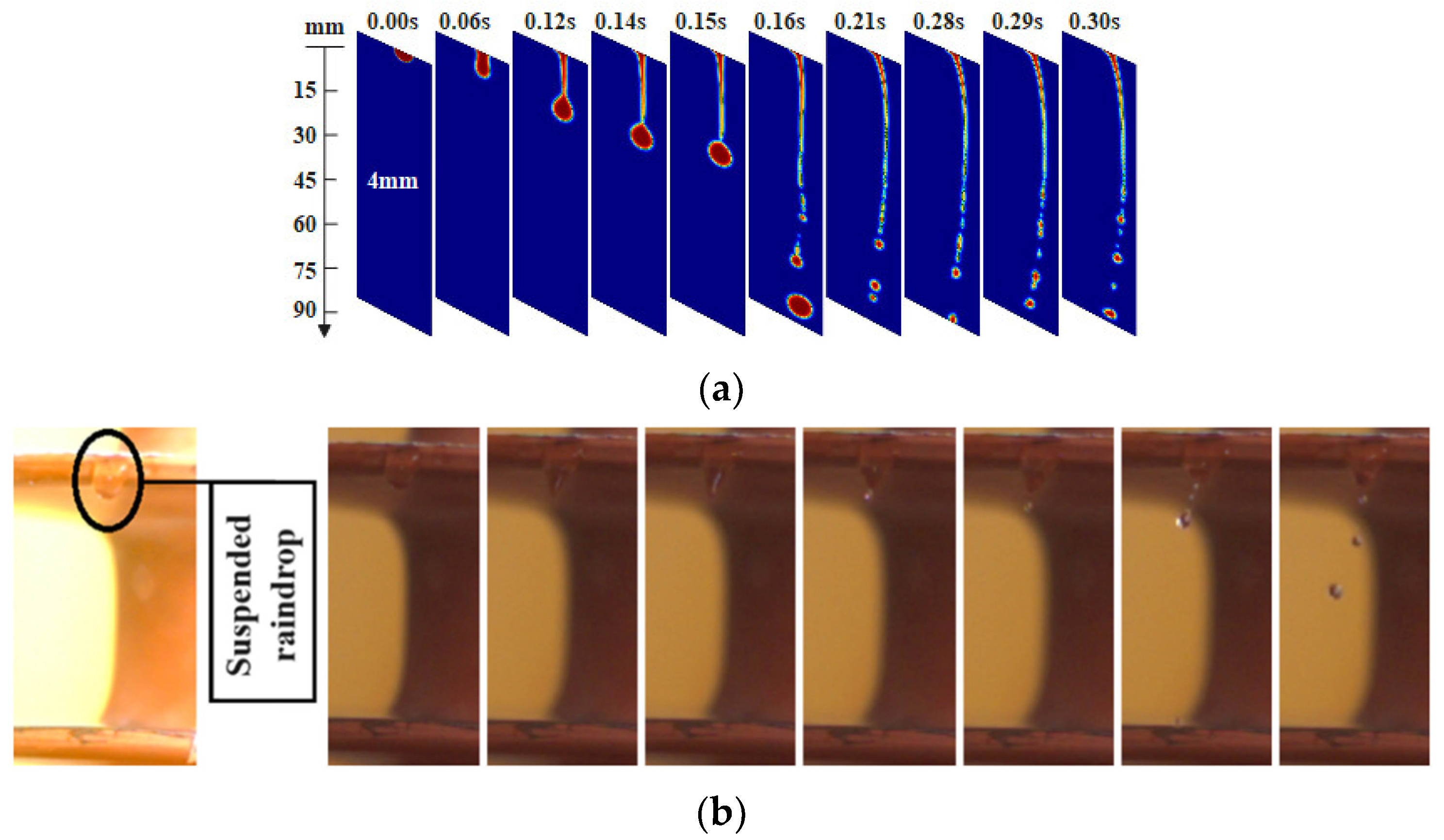
2.2. Characteristics and Mechanism of PRF Discharge

As is illustrated in Table 2, the breakdown of air gaps between sheds, which is trigged by the suspended raindrops at the edge of the shed, is an important part of the PRF process. Thus, the investigation of the morphology and variation in raindrops at the edge of the shed became the critical issue in revealing the mechanism of PRF. The results of the finite element analysis (FEA), which was a coupled simulation of the electric and fluid fields, are shown in Figure 4. In fluid simulation, the level set method (LSM) is used to reveal the deformation process of the raindrops. To confirm the simulation results, corresponding validation experiments are also carried out simultaneously.
The maximum value of the electric field strength around a suspended raindrop occurs at the vertex of the raindrop, where the discharge favorably occurs regardless of the raindrop’s morphology. The variation in the electric field distribution is the main reason for the occurrence of the discharge. Supplementary Material shows in detail the electric field distribution along the surface of the entire insulator during the PRF process. Furthermore, considering the deformation and conductivity of the raindrop, the spacing between adjacent sheds of the test post insulator is shortened by the elongation of the raindrop. Therefore, the discharge path tends to propagate preferentially along the air gap between the vertex of the raindrop and the edge of the lower shed, but rarely along the relatively dry surfaces between the sheds [31]. Figure 5 illustrates these discharge characteristics of PRF.
There are many suspended water droplets at the edge of the shed where the insulator is exposed to rain, and these droplets are all conditioned to generate a discharge. Although individual breakdowns between sheds do not significantly contribute to the risk of flashover of the whole insulator, when such breakdown between sheds occurs on multiple groups of adjacent sheds, the actual insulation distance of the insulator will be close to its insulation height, which will significantly reduce the electrical strength of the insulator. With the development of the discharge, small bridging arcs between multiple groups of sheds may be connected in series to form large arcs, and then flashover occurs.

3. Available Test Results

3.1. Influence of Rainfall Parameters

Regardless of whether the test is carried out for suspension insulators or post insulators, the test procedure is consistent with the procedure specified in the IEC standard [34,35], as shown in Figure 6. In artificial contamination tests, the fog is all-encompassing in wetting the surface of the contaminated insulator, whereas when rainfall is used instead of fog, the difference in the rainfall pattern will affect the results of the test. Among the factors that are included to influence this are the angle at which the raindrops fall, the intensity of the rainfall (precipitation rate), and the conductivity of the rain. In the interest of test equivalence, it is usual to carry out ‘artificial pollution rain flashover tests’ in which the raindrops are held at an angle of 45° to the horizon as they come into contact with the specimen. The results of the tests on the effect of the other two factors on the flashover voltage are shown in Figure 7; these tests were carried out on four composite post insulator specimens with different shed parameters.
Table 3 provides the parameters of the specimens used in the tests of Figure 7. As demonstrated in Figure 6, the effect of both precipitation rate and the conductivity of rainwater on the PRF voltage is nonlinear [36], which can be summarized in Equation (1), and the flashover voltage decreases as the values of these two parameters increase.
V P R F = p P · P n V P R F = p C · C n
where VPRF is the voltage of PRF; pP and pC are coefficients determined by the shed parameters and material of the insulator; P is the precipitation rate and C is the conductivity of rainwater; and n is the characteristic index that characterizes the effect of P or C on the VPRF.
It is also can be seen in Figure 6 that the shed parameters have a significant influence on the VPRF. The VPRF values of specimens with different shed parameters may have a variation of more than 25%. Consequently, improving the shed parameters of post insulators at the same insulation height would be of significant contribution to the enhancement of the VPRF.

3.2. Influence of Other Factors

3.2.1. Surface Contamination

In fact, the factors affecting the PRF voltage include three aspects: rainfall parameters, surface condition of the post insulator, and the shed parameters of the specimen. In particular, the surface condition mainly includes the degree of contamination, the distribution of pollution, and the material of the surface, which mainly reflects the state of hydrophobicity.
The effect of the degree of surface contamination on the PRF voltage is the same as in the case of the insulator’s pollution flashover, and the relationship is shown in Equation (2), as mentioned in many studies [2].
V P R F = p S · S n
where pS are coefficients determined by the shed parameters and material of the insulator; and S is the surface degree of pollution, which is usually characterized by the equivalent salt deposit density (ESDD: mg/cm2) or non-soluble deposit density (NSDD: mg/cm2).
The above results are inevitable because the surface pollution increases the conductivity and viscosity of the surface raindrops, which makes it easier for adjacent sheds to be short-circuited, and a continuous water-streamer can be formed between the sheds during the deformation of the suspended raindrops.

3.2.2. Distribution of Pollution

In the artificial flashover test, contamination distributes uniformly on the surface of a post insulator; however, the actual operating post insulators are not uniform in the distribution of pollution on the surface, and the degree of pollution on the lower surface of the shed is usually higher than that on the upper surface. Test results of our previous study are shown in Figure 8, which compares the PRF voltages for three different ratios of upper and lower surface pollution degree at different values of surface NSDD. It is indicated that the effect of the distribution of pollution on the PRF voltage is within 5%, which means that we do not need to pay special attention to the distribution of pollution on the insulator’s surface.

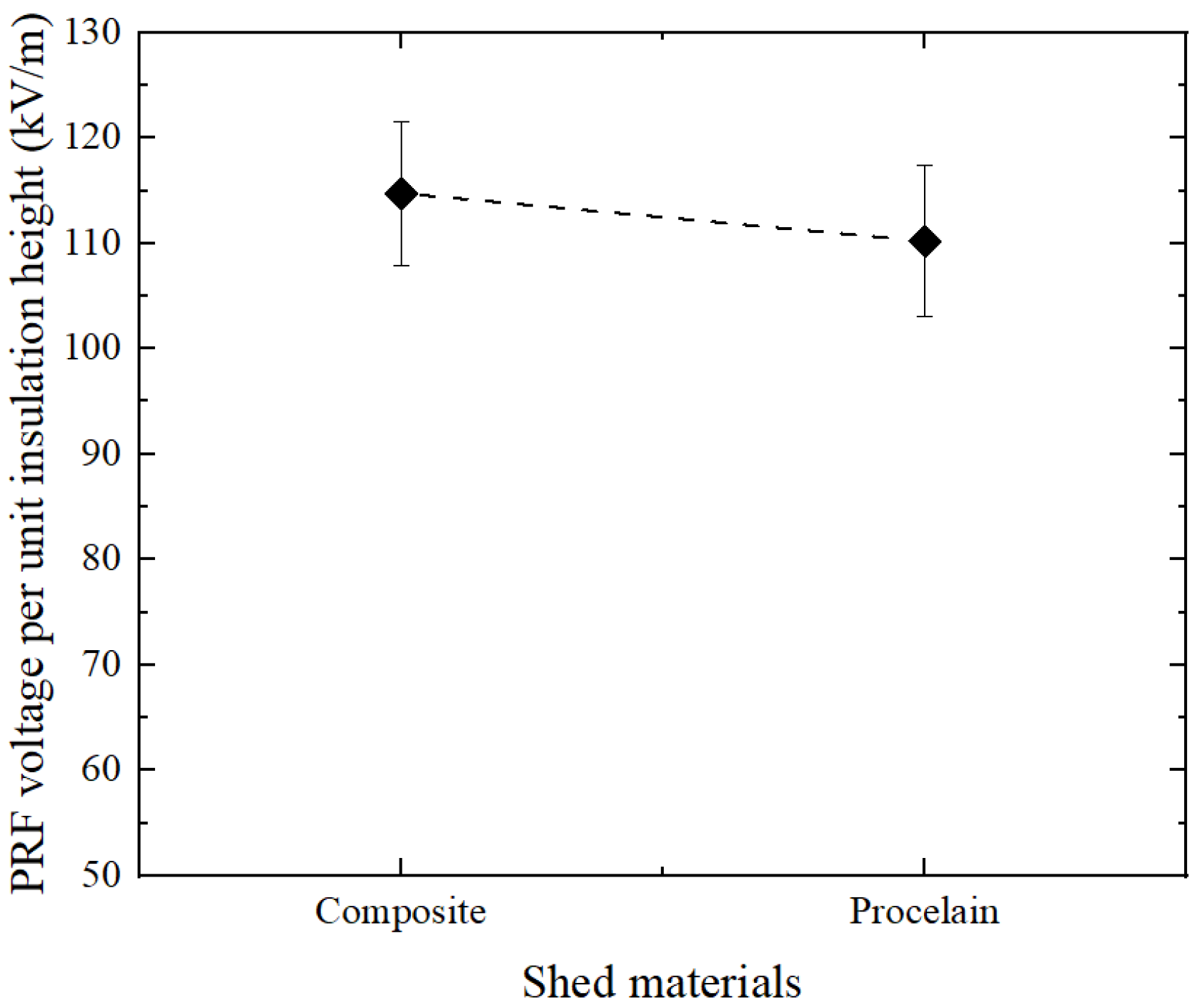
3.2.3. Material of the Shed

Post insulators can be classified into porcelain post insulators and composite post insulators according to their shed materials. Different shed materials have different hydrophobicity levels. Composites (which are usually high-temperature-vulcanized silicone rubber) perform better in PF as the excellent hydrophobicity effectively prevents the surface pollution layer from being wetted [37]. However, both composite and porcelain sheds inevitably form suspended raindrops at the edge; thus, there is little difference in PRF performance between them. The average values of PRF voltages per unit insulation height of three composite post insulators with different shed parameters are given in Figure 9 in comparison with the average values of PRF voltages of three porcelain post insulators. The average PRF voltage of composite post insulators is approximately 4.11% higher than that of porcelain post insulators, in spite of having different shed parameters and materials.

3.2.4. Shed Parameters

Compared to porcelain post insulators, the shed parameters of composite post insulators are more easily changed during manufacturing by varying the parameters of the mold, and the sheds are usually produced by an injection molding process. The optimization of shed parameters for suspended composite insulators has received consideration in some works [38]. The process of optimization of shed parameters is described as follows:
  • Design and production of multiple molds with different parameters;
  • Production of insulator specimens with different shed parameters by injection molding using the above molds;
  • Tests were carried out on specimens to obtain the flashover characteristics;
  • Comparison and analysis of the test results to select the specimen with the optimum external insulation characteristics.
In recent years, as machine learning and other techniques have been applied in a wider range of fields and the amount of experimental data has continued to increase, it has become possible to use new methods to realize the optimization of shed parameters, which is discussed in Section 4.2.

4. Discharge Prevention and Application

The fundamental cause of discharges occurring on the insulator’s surface is an alteration of the electric field in an area where the electric field is distorted to ionize the air. According to the explanation of the discharge mechanism in Section 2, it can be found that the raindrops on the edge of the shed play the role of enhancing the local electric field; therefore, it is inferred that the discharge can be obstructed by preventing the formation of water streamers between adjacent sheds. In addition, the longer the length of the dry area on the insulator’s surface, the higher its flashover voltage. Consequently, it mimics the umbrellas that people use to prevent getting wet on rainy days, and rainproof sheds are used to improve the PRF performance of post insulators [39].

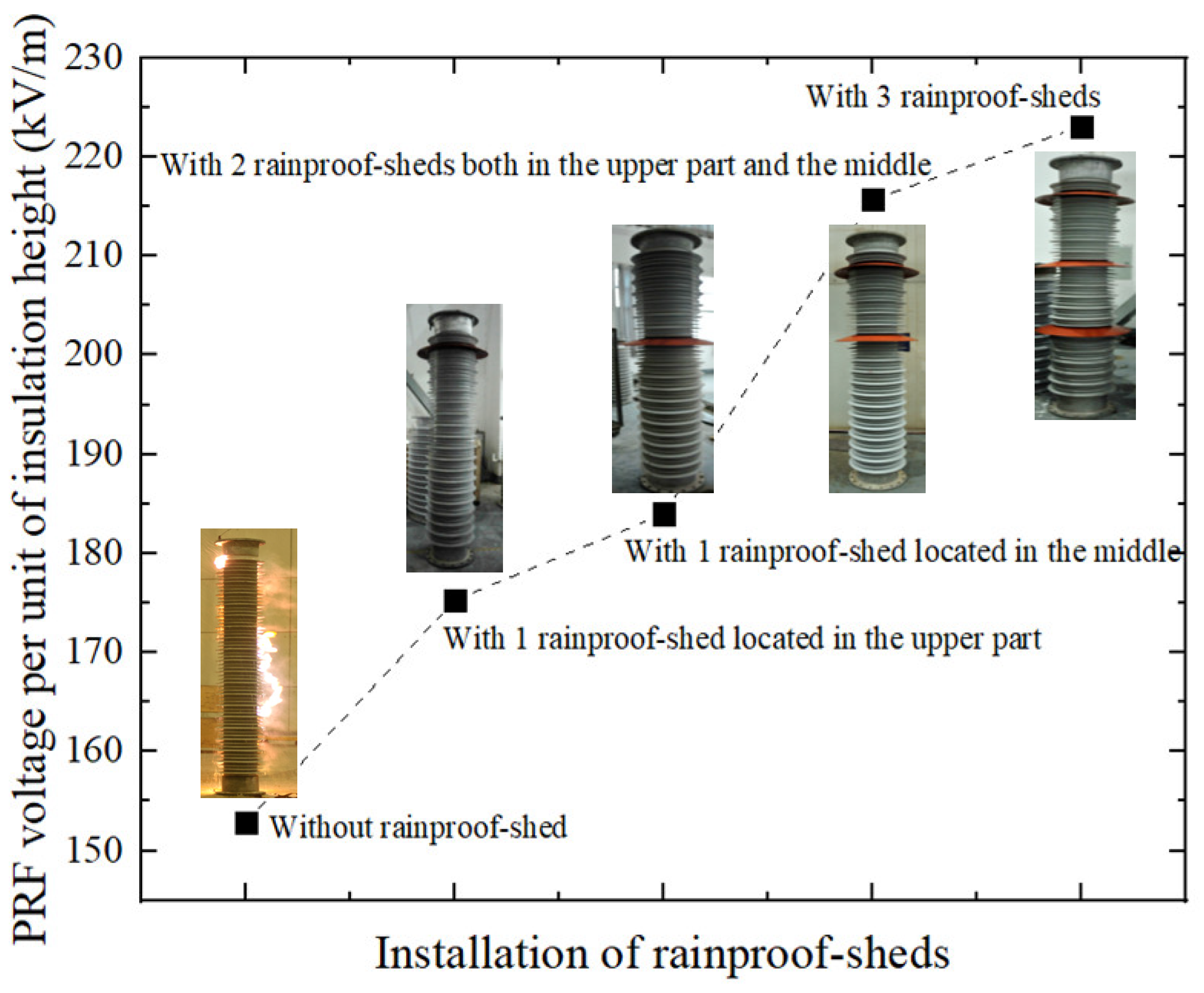
4.1. Application of Rainproof Sheds

The rainproof shed is a circular silicone rubber shed with larger dimensions (with a diameter of 640 mm after installation) glued to the existing shed of the post insulator, thus increasing the surface insulation distance and preventing continuous water streamers between the sheds. A series of tests have been carried out on the effect of the location and number of rainproof sheds on the PRF voltage, and the results are shown in Figure 10. The tests were carried out on large-diameter post insulator specimens (with a rod diameter of 294 mm) used in UHV converter stations, to which a negative DC voltage was applied during the test. The surface of the specimen was not contaminated in this test and the precipitation rate was 8 mm/min.
The experimental results in Figure 6 show that the voltage can be increased by 14.65% to 45.91% under the same experimental conditions after the installation of the rainproof sheds compared to the case without the rainproof sheds. And the more rainproof sheds are used, the greater the increase in PRF voltage. However, it is worth noting that if the rainproof sheds are arranged overly densely, i.e., two adjacent sheds are too close to each other, then they may be connected by water streamers, which negates the effectiveness in the prevention of PRF. Moreover, the best results are achieved by installing the rainproof shed in the middle of the post insulator when only one rainproof shed is used.
The use of rainproof sheds increases the equivalent diameter of the post insulator, which may affect the insulation distance between the insulator and the surrounding equipment. In addition, rainproof sheds are an add-on component to the original design and cannot be installed under live conditions. Previous experimental results have shown that post insulators with different shed parameters have different PRF characteristics, which makes the optimal design of shed parameters a better way of preventing PRF.

4.2. Optimized Design of Shed Parameters

Based on the traditional shed optimization methods presented in Section 3.2.4, applying an artificial neural network is an excellent way to carry out shed parameter optimization [40]. The PRF test results of 20 composite post insulator specimens with different shed parameters (including spacing distance between adjacent sheds, extension length, combination of sheds, rod diameter, etc.) were collected, and an optimization–prediction model based on a back propagation (BP) neural network, which is shown in Figure 11, was established. This model converts a multi-objective optimization problem into a single-objective optimization problem, i.e., PRF voltage is the only optimization objective, and the shed parameters are used as decision variables. Additionally, it should be noted that the use of the optimization model with respect to profile optimization needs to be decided in field enhancement analysis.
The recommended shed parameters of composite post insulators used in the UHV project, as indicated by the results of the optimization, are a spacing distance between adjacent sheds (S1 in Table 2) acceptably in the range of 80 mm and 90 mm, and an average shed extension length in the range of 85 mm to 95 mm. In addition, the experimental results in Figure 7 also indicated that the larger the rod diameter of the post insulator, the lower the PRF voltage. Conversely, the higher the operating voltage, the larger the rod-diameter of post insulators in a transmission project [31]. Consequently, parameter optimization has a more significant importance in UHV projects.
Furthermore, the change in the profile of sheds also affects the electric field distribution. The morphology of raindrops, which is highly related to the profile of a shed, is critical in the PRF process. Therefore, the concept of shed micro-parameters, which includes the inclination angle of the upper and lower shed surfaces, the chamfering of the shed edge, etc., needs to be paid more attention in further studies.

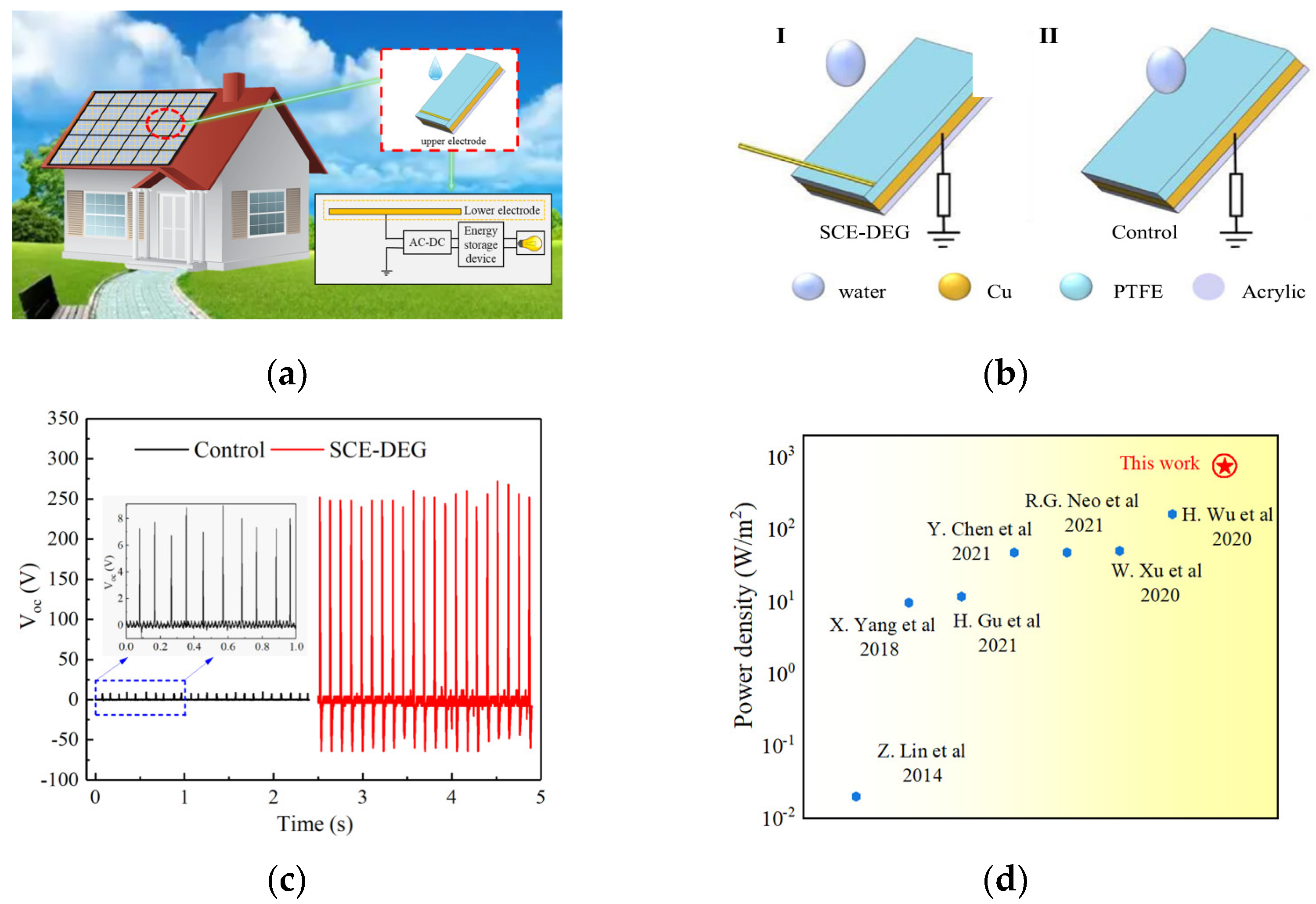
4.3. Utilization of Raindrop Energy

Droplet discharge is a critical feature of the PRF, which indicates that droplets cause energy variations as they move over the surface of the material. In fact, a droplet-based electricity generator (DEG) has been demonstrated to be an efficient method of harvesting energy from the natural environment. Moreover, a droplet-based electricity generator with a simple open structure (SCE-DEG), shown in Figure 12, was proposed in an interesting study [41].
The energy variation in raindrops during PRF was of little concern in previous studies; further research on this issue can be carried out to provide a better understanding of the mechanism of PRF.

5. Conclusions and Prospects

Pollution rain flashover (PRF) is an issue that needs to be highlighted in the inspection of external insulation equipment in UHV converter stations. This study first clarified the concept of PRF of post insulators under DC voltage. Compared to the pollution flashover (PF) that occurs in fog, PRF is characterized by the following main features: firstly, the local electric field distortion triggered by the suspended raindrops at the edges of the shed is the inducing factor of the discharge. Secondly, the discharge induced by the suspended raindrops is the breakdown of the air gap between sheds rather than the flashover along the insulating surfaces. In addition, the discharge between sheds is constantly changing and moving during the PRF process, and the final flashover of the entire insulator is the series connection of multiple groups of arcs between the sheds.
Based on the results of the available experimental and simulation studies, the following conclusions need to be emphasized.
The PRF voltage is affected by various factors including rainwater conductivity, insulator shed parameters, rod diameter, surface contamination and its distribution, shed material, etc. The conductivity of the suspended raindrops that cause the discharge and the shed parameters have the greatest effect on the PRF voltage. By optimizing the shed profile, the PRF performance of post insulators can be effectively improved.
When taking full account of the installation conditions in the application, rainproof sheds can significantly improve the performance of the PRF.
For future work, it is recommended that the following issues be further investigated:
  • Energy variation in surface raindrops on post insulators in rainy weather;
  • PRF characteristics under AC voltages and a comparison of the results with those under DC voltages;
  • Modification and enhancement of the shed materials of post insulators;
  • Discharge mechanism of a gap between electrodes in rainy weather.

Supplementary Materials

The following supporting information can be downloaded at https://www.mdpi.com/article/10.3390/en17164137/s1, Video S1: PRF process of large-diameter composite post insulator under 2 mm/min rainfall.

Author Contributions

Investigation and writing—original draft preparation Y.D. (Yuxi Dong); data analysis, Z.W.; supervision, M.D.; data curation, X.W.; investigation and project administration, Y.D. (Yu Deng); methodology, B.C.; project design, Y.X.; conceptualization, writing—review and editing, and funding acquisition, C.Z. All authors have read and agreed to the published version of the manuscript.

Funding

This research was partially funded by the National Natural Science Foundation of China, grant numbers 52377162 and 51907178, and partially funded by the 2023 Annual Open Funds of Tibet Yangbajing High Altitude Electrical Safety and Electromagnetic Environment National Observation and Research Station, grant number GY80-23-006.

Institutional Review Board Statement

Not applicable. This study did not involve humans or animals.

Informed Consent Statement

Not applicable.

Data Availability Statement

The original contributions presented in the study are included in the article, further inquiries can be directed to the corresponding author.

Acknowledgments

The authors gratefully acknowledge the contributions of Fuzeng Zhang and Yifan Liao of the CSG Electric Power Research Institute and all members of the National Engineering Laboratory (Kunming) for UHV Engineering Technology for their work on this paper.

Conflicts of Interest

Author Ying Xu was employed by the company State Grid Economic and Technological Research Institute Co. The remaining authors declare that the research was conducted in the absence of any commercial or financial relationships that could be construed as a potential conflict of interest.

References

  1. Jaelani, A.A.; Haya, S.N.; Lumba, L.S.; Suwarno, S. Effect of Artificial Aging on Silicone Rubber Polymeric Insulators Performance at Various Environmental Conditions. In Proceedings of the 2021 3rd International Conference on High Voltage Engineering and Power Systems (ICHVEPS), Bandung, Indonesia, 5–6 October 2021; pp. 79–84. [Google Scholar]
  2. Salem, A.A.; Lau, K.Y.; Rahiman, W.; Abdul-Malek, Z.; Al-Gailani, S.; Mohammed, N.; Rahman, R.A.; Al-Ameri, S.M. Pollution flashover voltage of transmission line insulators: Systematic review of experimental works. IEEE Access 2022, 10, 10416–10444. [Google Scholar] [CrossRef]
  3. Mousalreza, F.P.; Sina, M.; Mohammad, M.; Amin, M. Designing an Automatic Detector Device to Diagnose Insulator State on Overhead Distribution Lines. IEEE Trans. Ind. Inform. 2022, 18, 1072–1082. [Google Scholar]
  4. Wang, R.; Xu, Y.; Jiang, C.; Peng, X.; Yu, Z.; Xie, Y.; Xie, Y.; Hu, C. Simulation and analysis of charge accumulation characteristics of post insulator of transmission line for the CRAFT NNBI system. Fusion Eng. Des. 2021, 173, 112948. [Google Scholar] [CrossRef]
  5. Xin, Q. Assessment of the External Insulation Performance of Post Insulator in Rain: A Review. IOP Conf. Ser. Earth Environ. Sci. 2021, 781, 042048. [Google Scholar]
  6. Mirza, S.; Peter, K.; Pihler, P. New design of a medium voltage indoor post insulator. IEEE Trans. Dielectr. Electr. Insul. 2017, 24, 1162–1168. [Google Scholar]
  7. Anthony, C.B.; Stephen, B.; Allen, B.R.; Glenn, A.D.; DeSantis, N.; Shawn, E.; Kevin, E.; Michael, G.; Robert, K.; Niedospial, E.; et al. High Voltage Composite Line Post Insulators Combined Load Limits. IEEE Trans. Power Deliver. 2023, 38, 38–45. [Google Scholar]
  8. He, S.; Song, Y.; Huang, H.; He, Y.; Zhou, S.; Gao, Z. Meteorological Characteristics of a Continuous Ice-Covered Event on Ultra-High Voltage Transmission Lines in Yunnan Region in 2021. Atmosphere 2024, 15, 389. [Google Scholar] [CrossRef]
  9. Du, B.X.; Liang, H.C.; Li, J. Surface coating affecting charge distribution and flashover voltage of cone-type insulator under DC stress. IEEE Trans. Dielectr. Electr. Insul. 2019, 26, 706–713. [Google Scholar] [CrossRef]
  10. Yang, L.; Hao, Y.P.; Li, L.C.; Zhao, Y.M. Comparison of pollution flashover performance of porcelain long rod, disc type, and composite UHVDC insulators at high altitudes. IEEE Trans. Dielectr. Electr. Insul. 2012, 19, 1053–1059. [Google Scholar] [CrossRef]
  11. Ghosh, P.; Das, A.K.; Dalai, S. The effects of non-standard lightning impulse on electrical insulation: A review. Electr. Eng. 2022, 104, 4239–4254. [Google Scholar] [CrossRef]
  12. Chun, L.S.; Chang Shen, O.; Eng Eng, N. An Integrated Lightning Risk Assessment of Outdoor Air-Insulated HV Substations. Energies 2022, 15, 7702. [Google Scholar] [CrossRef]
  13. Gençoğlu, M.T.; Cebeci, M. The pollution flashover on high voltage insulators. Electr. Power Syst. Res. 2008, 78, 1914–1921. [Google Scholar] [CrossRef]
  14. Salem, A.A.; Abd, R.R.; Al-Ameri, S. Pollution flashover characteristics of high-voltage outdoor insulators: Analytical study. Arab. J. Sci. Eng. 2022, 47, 2711–2729. [Google Scholar] [CrossRef]
  15. Zhang, D.D.; Xu, H.; Huang, X.N.; Zhang, Z.J.; Jiang, X.L. Space Electric Field Characteristics of Silicone Rubber Insulator Pollution Flashover and Its Application in Flashover Prewarning. IEEE Trans. Dielectr. Electr. Insul. 2023, 30, 439–448. [Google Scholar] [CrossRef]
  16. Salem, A.A.; Abd-Rahman, R.; Rahiman, W.; Rahiman, W.; Al-Gailani, S.A.; Al-Ameri, S.M.; Ishak, M.T.; Sheikh, U.U. Pollution flashover under different contamination profiles on high voltage insulator: Numerical and experiment investigation. IEEE Access 2021, 9, 37800–37812. [Google Scholar] [CrossRef]
  17. Wadie, F. Investigative analysis of the impact of the climatic induced pollution upon the insulators in 500 kV HVDC transmission line. Electr Power Syst. Res. 2023, 220, 109244. [Google Scholar] [CrossRef]
  18. Yang, L.; Hao, Y.P.; Li, L.C.; Zhang, F.Z. Artificial pollution flashover performance of porcelain long rod UHVDC insulators at high altitudes. IEEE Trans. Dielectr. Electr. Insul. 2014, 21, 1965–1971. [Google Scholar] [CrossRef]
  19. Li, J.; Wang, Z.; Meng, X.B.; Wang, L.M. Influence of Shed Shape on Direct-Current Pollution Flashover Voltage and Pressure Decrease Exponent. IEEE Access 2022, 10, 51804–51813. [Google Scholar] [CrossRef]
  20. Wang, X.; Wang, Z.M.; Chen, J.Y.; Shi, X.F.; Li, X.L. Surface Flashover Characteristics of Epoxy Resin Composites in SF6/CF4 Gas Mixture with DC Voltage. Energies 2022, 15, 4675. [Google Scholar] [CrossRef]
  21. Qi, B.; Yang, Z.D.; Yang, X.; Gao, C.J.; Lu, L.C.; Zhang, Y.; Li, L.; Sun, C.X.; Li, C.R. Effect of Different DC Prestressed Time on Flashover Characteristics of Epoxy Resin Under Polarity Reversal Voltage. IEEE Trans. Dielectr. Electr. Insul. 2022, 29, 1582–1589. [Google Scholar] [CrossRef]
  22. Mizuno, Y.; Maeda, M.; Kondo, K. Flashover Risk-Based Probabilistic Design of Transmission Line Insulators under Contamination Conditions. IEEE Trans. Power Deliver. 2023, 38, 3611–3620. [Google Scholar] [CrossRef]
  23. Meng, X.B.; Mei, H.W.; Zhu, B.; Yin, F.H.; Wang, L.M. Influence of contaminated location on streamer discharge. Electr. Power Syst. Res. 2023, 218, 109243. [Google Scholar] [CrossRef]
  24. Ma, J.Q.; Wang, X.F.; Zhang, R.Q.; Qi, Z.B.; Wang, W.W. Influence of Sheath Radial Crack on Flashover Arc and Leakage Current of Roof Silicon Rubber Insulator for High-Speed Train. IEEE Access 2022, 10, 19720–19731. [Google Scholar] [CrossRef]
  25. Sezavar, H.R.; Fahimi, N.; Shayegani, A.A. A Dynamic Intelligent Approach Based on Gaussian Function for Prediction of the Flashover Voltage Conditions on Polluted Polymer Insulators. IEEE Trans. Power Deliver. 2022, 37, 3458–3468. [Google Scholar] [CrossRef]
  26. Zhu, Y.C.; Zhou, R.W.; Zhang, Y.; Dang, X.S.; Huang, X.B. Review on flashover risk prediction method of iced insulator based on icing monitoring technology. Cold Reg. Sci. Technol. 2021, 185, 103252. [Google Scholar] [CrossRef]
  27. He, J.; Gorur, R.S. Flashover of insulators in a wet environment. IEEE Trans. Dielectr. Electr. Insul. 2017, 24, 1038–1044. [Google Scholar] [CrossRef]
  28. Chihani, T.; Mekhaldi, A.; Beroual, A.; Teguar, M.; Madjoudj, D. Model for polluted insulator flashover under AC or DC voltage. IEEE Trans. Dielectr. Electr. Insul. 2018, 25, 614–622. [Google Scholar] [CrossRef]
  29. Bing, G.; Fan, Y.; Zhang, S.Y.; Yao, D.G.; Kou, X.K.; Liu, Z.H.; Liu, C. The Movement Characteristics of Charged Haze Particles in Ionized Field and Its Influence on Contamination of Insulator. IEEE Trans. Magn. 2018, 54, 7203304. [Google Scholar]
  30. Yin, F.H.; Liu, P.Y.; Mei, H.W.; Wang, L.M.; Li, L.C.; Farzaneh, M. The Shed Hole Influence on the Electrical Performance of Composite Insulator. IEEE Access 2020, 8, 217447–217455. [Google Scholar] [CrossRef]
  31. Liao, Y.; Wang, Q.; Yang, L.; Kuang, Z.; Hao, Y.; Zhang, C. Discharge Behavior and Morphological Characteristics of Suspended Water-Drop on Shed Edge during Rain Flashover of Polluted Large-Diameter Post Insulator. Energies 2021, 14, 1652. [Google Scholar] [CrossRef]
  32. Sezavar, H.R.; Fahimi, N.; Hasanzadeh, S.; Akmal, A.A.S. Risk assessment of contaminated composite insulators in pre-flashover conditions. Electr. Power Syst. Res. 2024, 230, 110256. [Google Scholar] [CrossRef]
  33. Arshad; Nekahi, A.; McMeekin, S.G.; Farzaneh, M. Effect of pollution severity and dry band location on the flashover characteristics of silicone rubber surfaces. Electr. Eng. 2017, 99, 1053–1063. [Google Scholar] [CrossRef]
  34. IEC. Artificial Pollution Tests on High-Voltage Ceramic and Glass Insulators to Be Used on D.C. Systems; IEC TS 61245; International Electrotechnical Commission: Geneva, Switzerland, 2015. [Google Scholar]
  35. IEC. Artificial Pollution Tests on High-Voltage Ceramic and Glass Insulators to Be Used on A.C. Systems; IEC 60507; International Electrotechnical Commission: Geneva, Switzerland, 2013. [Google Scholar]
  36. Yang, L.; Kuang, Z.Q.; Sun, Y.J.; Liao, Y.F.; Hao, Y.P.; Li, L.C.; Zhang, F.Z. Study on Surface Rainwater and Arc Characteristics of High-Voltage Bushing with Booster Sheds Under Heavy Rainfall. IEEE Access 2020, 8, 146865–146875. [Google Scholar] [CrossRef]
  37. Zhang, C.; Wang, L.; Guan, Z. Investigation of DC discharge behavior of polluted porcelain post insulator in artificial rain. IEEE Trans. Dielectr. Electr. Insul. 2016, 23, 331–338. [Google Scholar] [CrossRef]
  38. Li, L.C.; Gu, Y.; Hao, Y.P.; Xue, Y.W.; Xiong, G.K.; Yang, L.; Zhang, F.Z. Shed Parameters Optimization of Composite Post Insulators for UHV DC Flashover Voltages at High Altitudes. IEEE Trans. Dielectr. Electr. Insul. 2015, 22, 169–176. [Google Scholar] [CrossRef]
  39. Sun, Y.J.; Yang, L.; Shang, G.F.; Kuang, Z.Q.; Liao, Y.F.; Hao, Y.P.; Li, L.C. Effects of dynamic deformation of pendant water drops on the electric field between hollow porcelain insulator sheds under extreme rainfall. High Voltage 2022, 7, 86–97. [Google Scholar] [CrossRef]
  40. Zhou, Z.; Li, H.W.; Wen, S.; Zhang, C. Prediction Model for the DC Flashover Voltage of a Composite Insulator Based on a BP Neural Network. Energies 2023, 16, 984. [Google Scholar] [CrossRef]
  41. Li, Z.; Yang, D.; Zhang, Z.; Lin, S.; Cao, B.; Wang, L.; Wang, L. A dropl et-based electricity generator for large-scale raindrop energy harvesting. Nano Energy 2022, 100, 107443. [Google Scholar] [CrossRef]
  42. Lin, Z.; Cheng, G.; Lee, S.; Pradel, K.C.; Wang, Z.L. Harvesting water drop energy by a sequential contact-electrification and electrostatic-induction process. Adv. Mater. 2014, 26, 4690–4696. [Google Scholar] [CrossRef]
  43. Yang, X.; Han, J.; Wu, F.; Rao, X.; Zhou, G.; Xu, C.; Li, P.; Song, Q. A novel retractable spring-like-electrode triboelectric nanogenerator with highly-effective energy harvesting and conversion for sensing road conditions. RSC Adv. 2017, 80, 50993–51000. [Google Scholar] [CrossRef]
  44. Gu, H.; Zhang, N.; Zhou, Z.; Ye, S.; Wang, W.; Xu, W.; Zheng, H.; Song, Y.; Jiao, J.; Wang, Z.; et al. A bulk effect liquid-solid generator with 3D electrodes for wave energy harvesting. Nano Energy 2021, 87, 106218. [Google Scholar] [CrossRef]
  45. Chen, Y.; Xie, B.; Long, J.; Kuang, Y.; Chen, X.; Hou, M.; Gao, J.; Zhou, S.; Fan, B.; He, Y.; et al. Interfacial Laser-Induced Graphene Enabling High-Performance Liquid−Solid Triboelectric Nanogenerator. Adv. Mater. 2021, 33, 2104290. [Google Scholar] [CrossRef]
  46. Rong, R.G.; Khoo, B.C. Towards a larger scale energy harvesting from falling water droplets with an improved electrode configuration. Appl. Energy 2021, 285, 116428. [Google Scholar]
  47. Xu, W.; Wang, Z. Fusion of Slippery Interfaces and Transistor-Inspired Architecture for Water Kinetic Energy Harvesting. Joule 2020, 4, 2523–2531. [Google Scholar] [CrossRef]
  48. Wu, H.; Mendel, N.; van den Ende, D.; Shui, L.; Zhou, G.; Mugele, F. Charge Trapping-Based Electricity Generator (CTEG): An Ultrarobust and High Efficiency Nanogenerator for Energy Harvesting from Water Droplets. Adv. Mater. 2020, 32, 2001699. [Google Scholar] [CrossRef]
Figure 1. Structure and composition of the post insulator.
Energies 17 04137 g001
Figure 2. Search results for research results related to insulator flashover.
Energies 17 04137 g002
Figure 3. Results of the search for the quantity of studies on the flashover of a post insulator in the rain.
Energies 17 04137 g003
Figure 4. Simulation and experimental results of the deformation process of the raindrop at the edge of the shed. (a) Deformation process of suspended raindrops with a root contact diameter of 4 mm; (b) validation experimental results.
Energies 17 04137 g004
Figure 5. Discharge characteristics of suspended raindrops.
Energies 17 04137 g005
Figure 6. Test procedure of the PRF.
Energies 17 04137 g006
Figure 7. Test results of the PRF on post insulators with different shed parameters and under different rainfall parameters. (a) Influence of the precipitation rate; (b) influence of the rainwater conductivity; (c) description of the shed parameters.
Energies 17 04137 g007
Figure 8. PRF voltages of composite post insulators under different conditions of pollution distribution. (a) Test results; (b) parameters of the specimen.
Energies 17 04137 g008
Figure 9. Comparison of PRF voltages of post insulators with different shed materials.
Energies 17 04137 g009
Figure 10. Test results on the effect of the rainproof shed on the flashover characteristics of post insulators in the rain.
Energies 17 04137 g010
Figure 11. Structure of the optimization model based on the BP neural network.
Energies 17 04137 g011
Figure 12. Design and high performance of the SCE-DEG [41]. (a) Application of SCE-DEG on the building’s roofs; (b) SCE-DEG and the control device of a traditional droplet-based triboelectric nanogenerator (TENG); (c) output voltage of SCE-DEG and the control device (load resistance RL of 100 MΩ); (d) comparison of the instantaneous power density obtained in this work with other reports [42,43,44,45,46,47,48].
Energies 17 04137 g012
Table 1. A brief comparison of a porcelain post insulator and composite post insulator.
Insulating Materials of ShedInsulating Materials of RodFlashover
Performance
Mechanical PropertiesAging
Characteristics
PorcelainAlumina
ceramics
Depends on operating environmentHigh capacity to withstand longitudinal mechanical stressesHigh resistance to aging
Silicone rubberFiberglass or epoxy resinStrong resistance to pollution flashoverCapability to withstand both longitudinal and tangential stressesAging of composites needs attention
Table 2. Comparison of PF, RF, and PRF.
ConceptPFRFPRF
Surface conditionContaminated surfacesClean surfaceContaminated surface
Wetting method of insulator’s surfaceMostly fogRainRain
Rainwater condition\Clean rainwaterRainwater of a certain conductivity
Discharge pathMainly along the surfaceAlong water streamer + air gapAlong the surface + air gaps between sheds
Flashover voltageLowestHighestMiddle (may be lower than PF voltage if the clearance between sheds is minimal)
Flashover processAccumulation of surface contamination—wetting—leakage current—dry-band—arc-creepage—flashoverShed bridging by water streamer—electric field distortion—flashoverCorona and streamer discharge of surface water droplets—deformation of surface raindrops—electric field distortion—breakdown of air gaps between sheds—flashover
Prevention and control methodsShed optimizationRainproof shedsBoth shed optimization and rainproof sheds
Table 3. Parameters of the specimens used in the tests of Figure 6.
Specimen No.Insulation Height: H (mm)S1/S2
(mm)
P1/P2
(mm)
Surface Insulation Length (mm)Rod Diameter
(mm)
1#92072/3671/543470147
2#123548/2464/314455184
3#122585/4087/704770264
Disclaimer/Publisher’s Note: The statements, opinions and data contained in all publications are solely those of the individual author(s) and contributor(s) and not of MDPI and/or the editor(s). MDPI and/or the editor(s) disclaim responsibility for any injury to people or property resulting from any ideas, methods, instructions or products referred to in the content.

