Article

A Single-Phase Ground Fault Line Selection Method in Active Distribution Networks Based on Transformer Grounding Mode Modification

1
Electric Power Research Institute, Yunnan Electric Power Grid Co., Ltd., Kunming 650217, China
2
The Key Laboratory of Smart Grid of Ministry of Education, Tianjin University, Tianjin 300072, China
3
School of Carbon Neutrality Science and Engineering, Anhui University of Science and Technology, Hefei 231131, China
*
Author to whom correspondence should be addressed.
Energies 2024, 17(18), 4743; https://doi.org/10.3390/en17184743
Submission received: 5 July 2024 / Revised: 14 September 2024 / Accepted: 19 September 2024 / Published: 23 September 2024
(This article belongs to the Section F3: Power Electronics)

Abstract

:
Reliable fault line selection technology is crucial for preventing fault range expansion and ensuring the reliable operation of distribution networks. Modern distribution systems with neutral earthing via arc extinguishing coil face challenges during single-phase ground faults due to indistinct fault characteristics and system sequence networks influenced by the grounding methods on the distributed generation side. These factors increase the difficulty of fault line selection. By analyzing the differences between the zero-sequence currents of feeder lines and neutral lines in active distribution networks with neutral earthing via arc extinguishing coil, a method for single-phase ground fault line selection has been proposed in this paper. This method involves switching from a neutral point ungrounded mode to a low-resistance neutral grounding mode using distributed generation grid-connected transformers under permanent fault conditions. Criteria based on the differences in zero-sequence current ratios before and after the grounding mode switch are established. Simulation validation using the Power Systems Computer Aided Design (PSCAD) platform has been conducted. The proposed method demonstrates strong tolerance to transition resistance, simple extraction of fault characteristic signals, and accurate fault line selection results.

1. Introduction

In modern distribution networks (DNs), neutral point grounding methods typically include neutral point ungrounded (NPU), low resistance neutral grounding (LRNG), flexible grounding (FG), and neutral earthing via arc extinguishing coil (NEVAEC). Among these, NEVAEC reduces the capacitive current following a fault, facilitates arc extinction, and prevents arc re-ignition, making it a widely used method in DNs.
In China, single-phase ground faults (SPGFs) occur most frequently in 6–35 kV DNs, at a rate of about 80%. DNs with NEVAEC are typically overcompensated, with weak fault steady-state characteristics, weak fault currents, and unstable arcs. These conditions make it impossible to use power direction characteristics and zero-sequence current magnitude characteristics for fault line selection (FLS) [1]. When permanent SPGFs occur in DNs with NEVAEC, the system can operate with symmetrical three-phase voltage for 1 to 2 h. However, if the grounded fault section is not disconnected in time, the insulation of non-faulted phases may break down, causing phase-to-phase short circuits and expanding the fault range. Therefore, timely and accurate FLS is crucial.
For economic reasons, some distribution networks usually install only a small number of fault detection devices at substations or feeder lines, and the composition of fault currents in the feeder lines becomes complicated when distributed generations (DGs) are connected [2,3,4]. Under these conditions of incomplete measurement of fault information, the traditional methods used by power companies to select and determine fault lines can easily lead to interruption of power supply to non-fault lines, thus affecting power quality and resulting in abnormal operation of sensitive power equipment [5]. Therefore, reliable selection of the single-phase ground fault line is of great significance for the distribution network with distributed generations [6, 7, 8].
The grounding methods of the main transformer in the DNs and the grid-connected transformers of distributed generations both affect the system’s zero-sequence impedance and ground fault current [9]. Traditional single-phase ground fault line selection methods in DNs, such as the steady-state method, transient method, and signal injection method [10,11,12], which do not consider the integration of DGs, cannot be directly applied to active distribution networks (ADNs) with a high proportion of DGs.
In ADNs with LRNG, the fault current magnitude varies depending on whether the grid-connected transformers of DGs are grounded directly or through low-resistance grounding, and this variation is influenced by the location of the fault point (upstream or downstream of the DG) [13,14]. Refs. [15,16] respectively discuss the relationship between the fault location and phase change in fault current in ADNs with a high proportion of DGs before and after the fault occurrence from the perspective of protective devices, as well as the trend in sequence current changes in upstream and downstream lines when a SPGF occurs. Through fault characteristic analysis, these studies provide an important basis for formulating FLS schemes. Additionally, Ref. [17] proposes a high-sensitivity grounding protection scheme and centralized FLS criteria based on the difference in zero-sequence current magnitude post-fault between the neutral line and feeder lines, which has been verified under a transition resistance of one thousand ohms. Ref. [18] utilizes the Mallat algorithm of wavelet transform to decompose and reconstruct the transient zero-sequence current of the line in DNs with NEVAEC, proposing a FLS scheme based on the transient zero-sequence current magnitude of the line. Ref. [19] calculates high-correlation time-frequency windows through cross-wavelet transform of zero-sequence currents of line fault, then extracts zero-sequence current sequences in high-correlation time-frequency windows for comparison of energy magnitude and phase verification to achieve FLS. Ref. [20] changes the modulation strategy of the inverter of a DG during SPGF, enabling the inverter to inject characteristic signals into the DNs for a short time, and ultimately achieves FLS by analyzing zero-sequence currents and comparing the energy of characteristic signals at various measurement points. Although the FLS criteria of the above methods are clear, the extraction and calculation of characteristic signals are relatively complex, and there is a high requirement for the selection of transient time window length, making it difficult to apply in practical engineering.
This paper focuses on the FLS method of ADNs with NEVAEC and proposes a FLS method based on steady-state zero-sequence electrical quantities. After a SPGF occurs in the ADNs, the neutral point grounding mode of the DG grid-connected transformer is switched from NPU to LRNG at DG side. The zero-sequence current characteristics of each feeder line after the switch were analyzed, leading to the proposal of a FLS criterion for ADNs with NEVAEC. The proposal FLS criterion aims to achieve accurate FLS for SPGF. Simulation analysis was conducted to validate the effectiveness and transient resistance capability of the proposed FLS method.

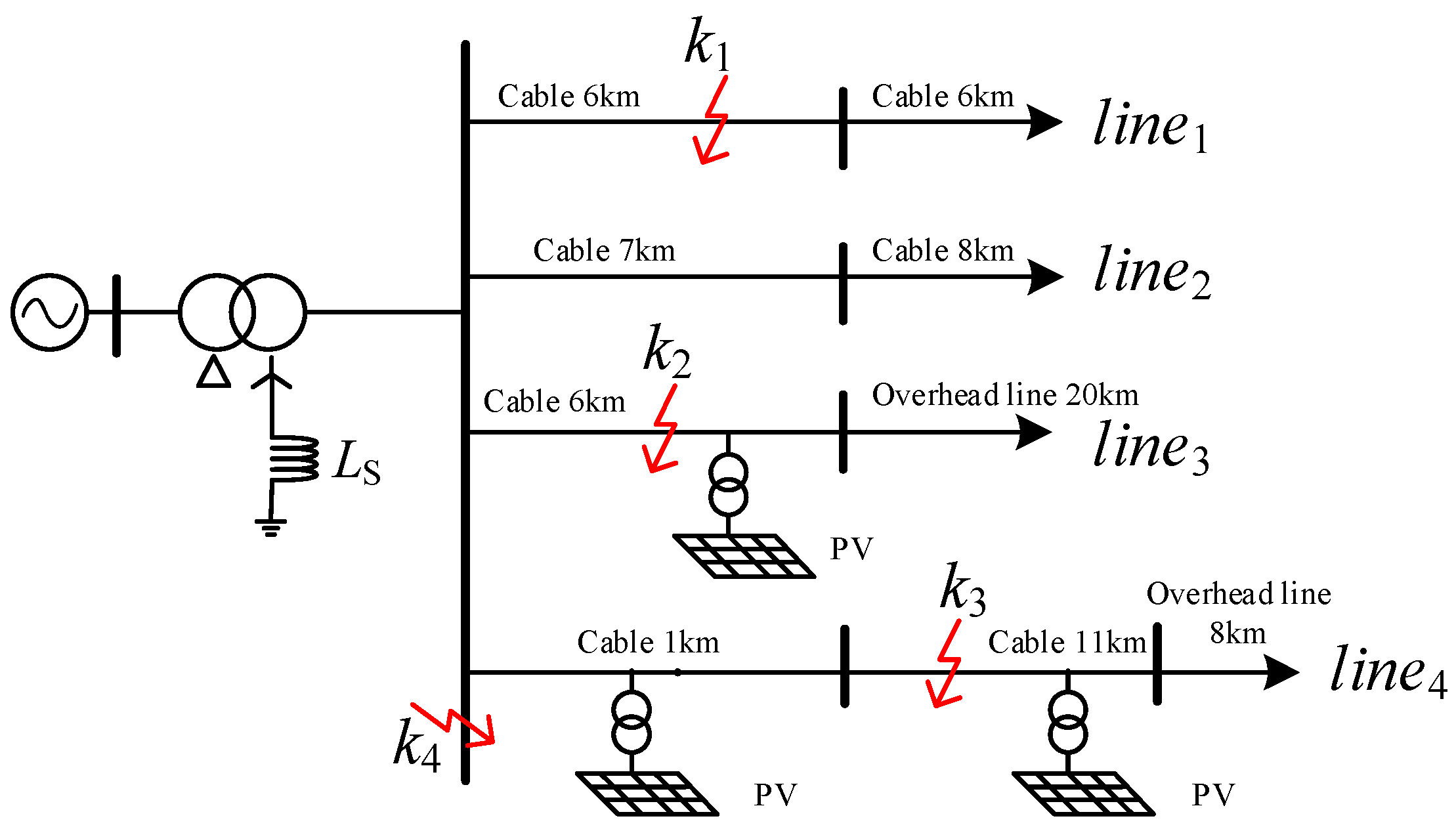
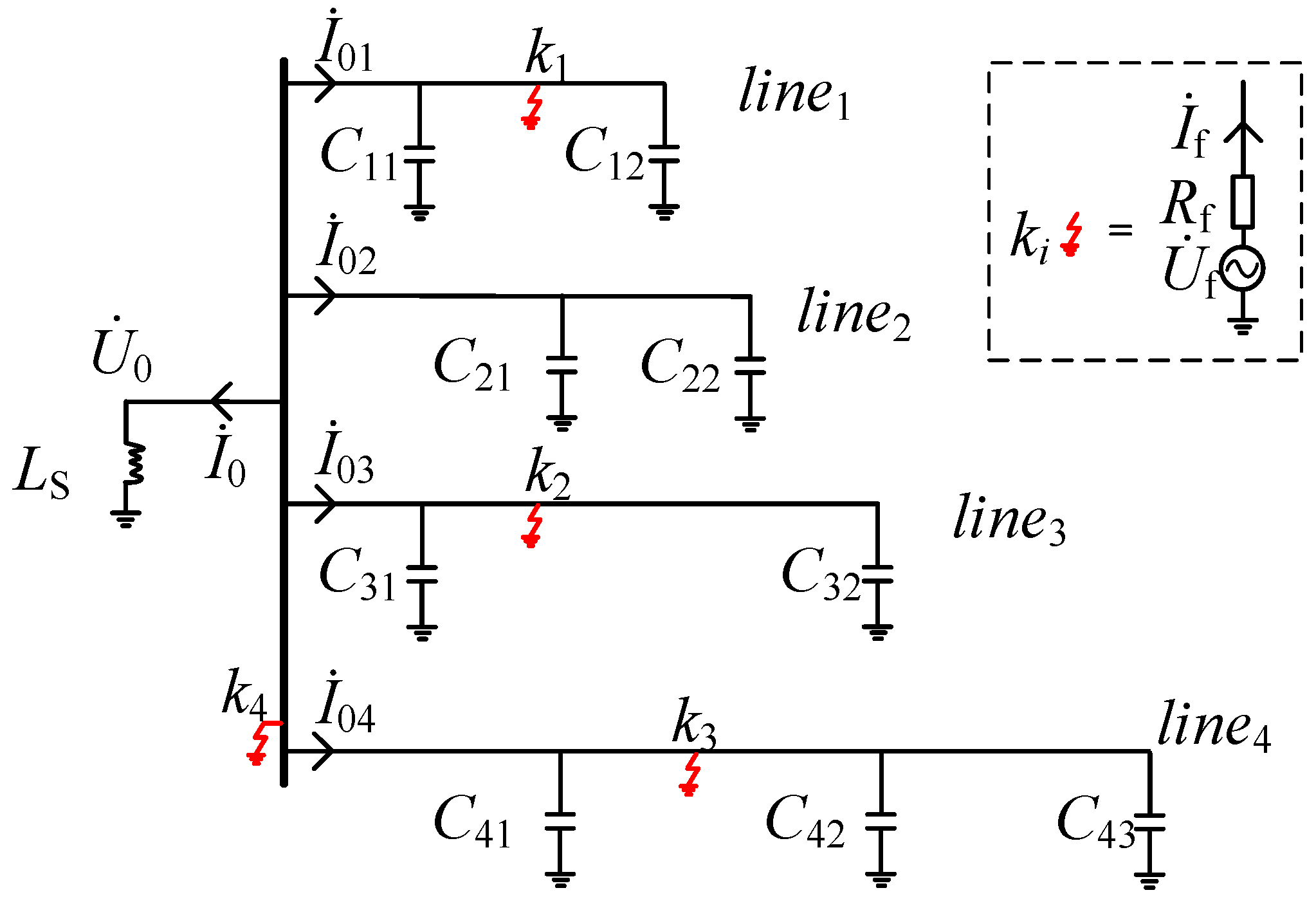
2. Analysis of SPGF Characteristics in ADNs with NEVAEC

Figure 1 illustrates a 10 kV DNs with DGs.
Where the neutral point grounding method is NEVAEC. The arc extinguishing coil is denoted as LS. The DG grid-connected transformer uses a Δ/Y wiring configuration.
Assuming the DNs experience a SPGF at point ki through a transition resistance Rf, the corresponding zero-sequence equivalent circuit of the fault is shown in Figure 2. Cip (i ∈ [1, 4], p ∈ [1, 3]) represents the equivalent capacitance to ground of the pth segment of feeder linei, and Ci denotes the sum of the equivalent capacitances to ground for the entire feeder linei. Uf is the zero-sequence equivalent voltage at the fault point, If is the zero-sequence current of the fault phase, I0i (i = 1, 2, 3, 4) represents the (Root Mean Square) RMS values of the zero-sequence currents at the exits of feeders line1 to line4 on the bus, U0 is the RMS value of the zero-sequence voltage at the bus, and I0 is the RMS value of the zero-sequence current flowing through the system neutral line. Here, the direction from the bus to the feeder is defined as positive, and the opposite direction is defined as negative.
In the network structure shown in Figure 2, when an SPGF occurs at point ki, the zero-sequence current in the system neutral line is given by:
I ˙ 0 = U ˙ 0 3 j ω L S
where U0 is the RMS value of the zero-sequence voltage at the bus and I0 is the RMS value of the zero-sequence current flowing through the system neutral line. LS is the inductance of the arc extinguishing coil. Uf is the zero-sequence equivalent voltage at the fault point, Rf is the fault transition resistance, If is the zero-sequence current of the fault phase. ki is the fault point.

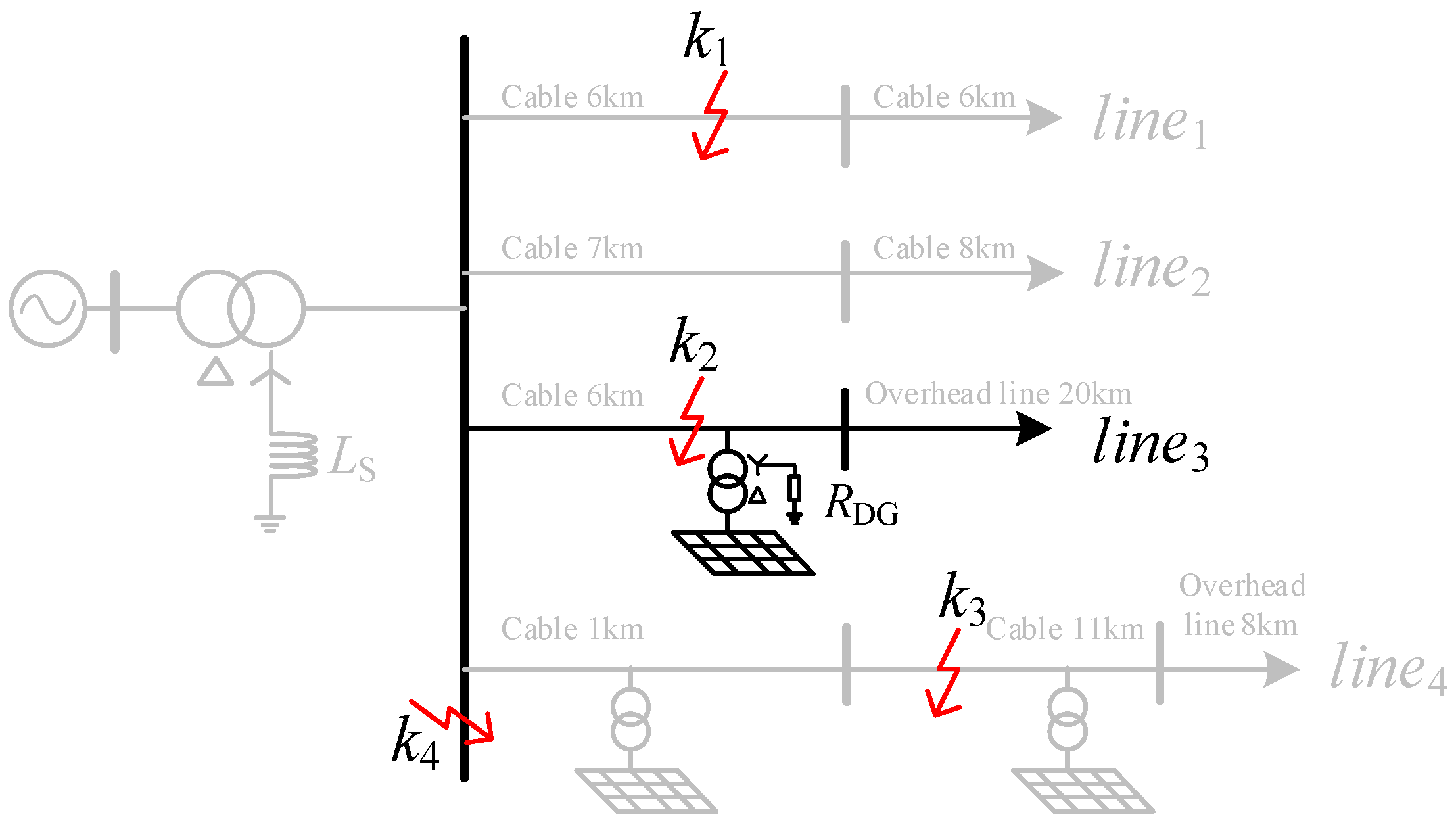
2.1. Fault in Feeder Line3 (Fault Point k2)

When a fault occurs at point k2, the following equation applies to the non-faulty feeders line1 and line2, which are not connected to DG, as well as to the non-faulty feeder line4, which is connected to DG.
I ˙ 01 = j ω C 1 U ˙ 0 I ˙ 02 = j ω C 2 U ˙ 0 I ˙ 04 = j ω C 4 U ˙ 0
At this time, the zero-sequence current at the exit of the faulted feeder line3 is the sum of the system’s neutral point zero-sequence current and the zero-sequence currents of all non-faulty feeders. Therefore, the zero-sequence current of the faulted line3 can be expressed as follows.
I ˙ 03 = I ˙ 01 + I ˙ 02 + I ˙ 04 + I ˙ 0 = j ω C 1 + j ω C 2 + j ω C 4 + 1 3 j ω L S U ˙ 0

2.2. Fault in Feeder Line4 (Fault Point k3)

When a fault occurs at point k3, the following equation applies to the non-faulty feeders line1 and line2, which are not connected to DG, as well as to the non-faulty feeder line3, which is connected to DG.
I ˙ 01 = j ω C 1 U ˙ 0 I ˙ 02 = j ω C 2 U ˙ 0 I ˙ 03 = j ω C 3 U ˙ 0
At this time, the zero-sequence current at the exit of the faulted feeder line4 is the sum of the system’s neutral point zero-sequence current and the zero-sequence currents of all non-faulty feeders. Therefore, the zero-sequence current of the faulted line4 can be expressed as follows.
I ˙ 04 = I ˙ 01 + I ˙ 02 + I ˙ 03 + I ˙ 0 = j ω C 1 + j ω C 2 + j ω C 3 + 1 3 j ω L S U ˙ 0

2.3. Fault in Bus (Fault Point k4)

For the case of a SPGF occurring at k4, the zero-sequence currents I0i in all other feeders in the DNs are equal to their respective equivalent capacitive currents to ground. The calculation method is similar to that in Equations (2) and (4). It can be expressed as follows:
I ˙ 01 = j ω C 1 U ˙ 0 I ˙ 02 = j ω C 2 U ˙ 0 I ˙ 03 = j ω C 3 U ˙ 0 I ˙ 04 = j ω C 4 U ˙ 0
Since the DG grid-connected transformers are ungrounded on the DG side, as shown in Figure 2, there are no zero-sequence current components in the system feeders other than those from the fault point ki in the analysis of zero-sequence currents following an SPGF. When the fault point involves a high-resistance SPGF, the zero-sequence current decreases as the transition resistance increases. Consequently, the DNs may fail to accurately identify the faulted line due to indistinct fault characteristics and the inability of feeder exit CTs to detect electrical changes [21,22].
In fact, the more variable structure of the DNs with the integration of DGs can be utilized to design effective SPGF FLS methods. By reasonably modifying the DG-side wiring of DG grid-connected transformers, differences in the system’s zero-sequence characteristics can be introduced without altering the grounding method of the system’s neutral point. These characteristic differences can then be used to construct fault indicators, enabling reliable FLS for SPGF.

3. Construction of FLS Criteria for SPGF

As shown in Figure 3, line3 is selected for modification. The DG side of the grid-connected transformer for the DG on line3 is changed from ungrounded to grounded via a low resistance RDG, which can be flexibly switched. Under normal operation, the switch remains open. When a permanent fault is detected in the system, the grounding resistor RDG is engaged at time t.
Similarly, the zero-sequence equivalent circuit of the system when an SPGF occurs after the DNs are modified can be obtained, as shown in Figure 4.
From the network structure, it can be inferred that when an SPGF occurs at point ki, the zero-sequence current I’0 in the system neutral line is:
I ˙ 0 = U ˙ 0 3 j ω L S
Considering that the zero-sequence circuit remains consistent with Section 2.1 before the grounding resistor RDG is engaged, the process of solving for the zero-sequence quantities will not be reiterated here.

3.1. Fault in the Modified Feeder Line3 (Fault Point k2)

When a fault occurs at point k2 and the grounding resistor RDG is engaged, for the non-faulty feeder lines 1 and 2, which are not connected to DGs, as well as for the non-faulty feeder line4, which is connected to DGs, the following applies:
I ˙ 01 = j ω C 1 U ˙ 0 I ˙ 02 = j ω C 2 U ˙ 0 I ˙ 04 = j ω C 4 U ˙ 0
Here, Ci represents the sum of the equivalent capacitances to ground for feeder line i. At this point, the zero-sequence current in the faulted feeder line3 is the sum of the system’s neutral point zero-sequence current and the zero-sequence currents of all non-faulty feeder lines, given by:
I ˙ 03 = j ω C 1 + j ω C 2 + j ω C 4 + 1 3 j ω L S U ˙ 0

3.2. Fault in the Non-Modified Feeder Line4 (Fault Point k3)

When a fault occurs at point k3 and the grounding resistor RDG is engaged, for the non-faulty feeder line1 and line2, which are not connected to DGs, as well as for the non-faulty feeder line3, which is connected to DGs, the following applies:
I ˙ 01 = j ω C 1 U ˙ 0 I ˙ 02 = j ω C 2 U ˙ 0 I ˙ 03 = 1 3 R DG + j ω C 3 U ˙ 0
At this point, the zero-sequence current in the faulted feeder line4 is:
I ˙ 04 = j ω C 1 + C 2 + C 3 + 1 3 j ω L S + 1 3 R DG U ˙ 0

3.3. Fault in the Bus (Fault Point k4)

When a fault occurs at the bus (fault point k4) and the grounding resistor RDG is engaged, the calculation method for the zero-sequence currents in the non-faulty feeder lines 1 and 2, which are not connected to DGs, as well as for the zero-sequence currents in the non-faulty feeder lines 3 and 4, which are connected to DGs, is similar to Equations (8) and (10). The corresponding expressions are as follows:
I ˙ 01 = j ω C 1 U ˙ 0 I ˙ 02 = j ω C 2 U ˙ 0 I ˙ 03 = 1 3 R DG + j ω C 3 U ˙ 0 I ˙ 04 = j ω C 4 U ˙ 0

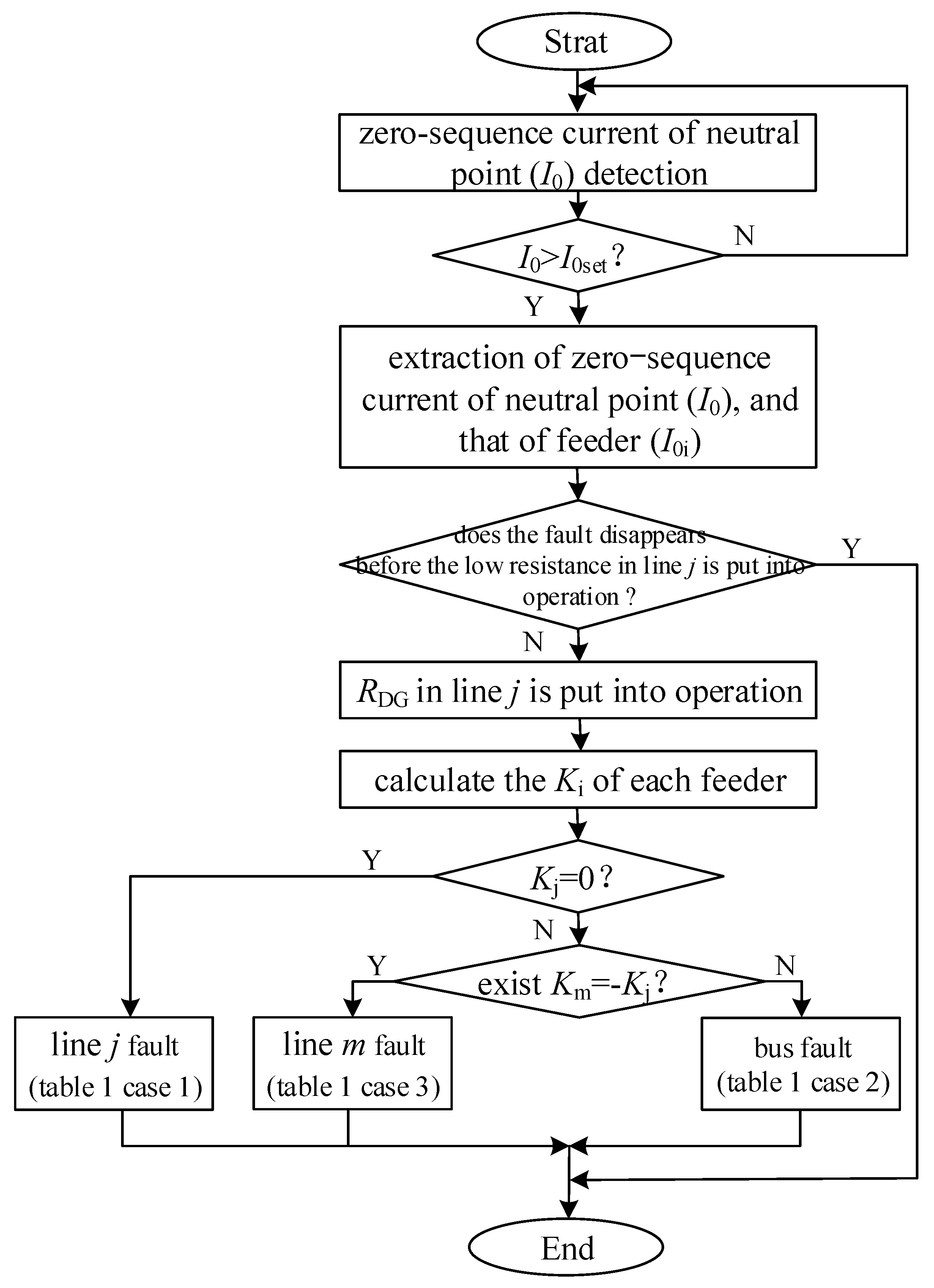
3.4. FLS Method and Criteria

Ki is defined as the FLS criterion for a SPGF in a DNs with integrated DGs, as shown in the following equation:
K ˙ i = R DG I ˙ 0 i I ˙ 0 I ˙ 0 i I ˙ 0
where I0i/I0 represents the ratio of the zero-sequence current at the exit of the ith feeder to the zero-sequence current in the neutral line before modification, and I0i/I0 represents the ratio of the zero-sequence current at the exit of the ith feeder to the zero-sequence current in the neutral line after modification.
Furthermore, by integrating Equations (1)–(13), the criteria are calculated, and the results are classified according to the different locations where the SPGF occurs in the lines.
When an SPGF occurs on the modified line3 (fault point k2), the following applies:
K ˙ 1 = R DG I ˙ 01 I ˙ 0 I ˙ 01 I ˙ 0 = R DG j ω C 1 U ˙ 0 U ˙ 0 3 j ω L S j ω C 1 U ˙ 0 U ˙ 0 3 j ω L S = 0 K ˙ 2 = R DG I ˙ 02 I ˙ 0 I ˙ 02 I ˙ 0 = 0 K ˙ 3 = R DG I ˙ 03 I ˙ 0 I ˙ 03 I ˙ 0 = 0 K ˙ 4 = R DG I ˙ 04 I ˙ 0 I ˙ 04 I ˙ 0 = 0
When an SPGF occurs on the non-modified line4 (fault point k3), the following applies:
K ˙ 1 = 0 K ˙ 2 = 0 K ˙ 3 = ω L S 90 ° K ˙ 4 = ω L S 90 °
When an SPGF occurs on the bus (fault point k4), the following applies:
K ˙ 1 = 0 K ˙ 2 = 0 K ˙ 3 = ω L S 90 ° K ˙ 4 = 0
Based on the calculation results, the FLS criteria can be summarized, as shown in Table 1.
Since this method only modifies the DG-side grounding method of a single DG grid-connected transformer on one feeder, there will not be more than one non-zero Ki when the DNs structure is an active radial type.
Overall, the proposed FLS method is outlined in the flowchart shown in Figure 5.
Step 1, When the neutral point zero-sequence current I0 exceeds the set value Iset, the protection is activated. At the same time, the zero-sequence currents of all feeder lines I0i (i = 1, 2, 3…j…) and the neutral line zero-sequence current I0 are sampled for one power frequency cycle before the low resistance RDG is engaged.
Step 2, If the zero-sequence current I0 at the neutral point returns to normal after the detection, it indicates that the fault has disappeared, and the FLS process ends; otherwise, proceed to Step 3.
Step 3, After engaging the low resistance RDG on the jth line (the modified line), the zero-sequence currents I’0i (i = 1, 2, 3…j…) of all feeder lines and the neutral line zero-sequence current I’0 are obtained for one power frequency cycle using FFT, after a delay of 0.05 s.
Step 4, Calculate Ki (i = 1, 2, 3…j…) according to Equation (13). If all Ki (i = 1, 2, 3…j…) are zero, it is determined that a fault has occurred on the jth line, the modified line. If Km = −Kj (mj) and Ki = 0 (i = 1, 2, 3…, but im and ij), it is determined that a fault has occurred on the mth line. If Kj ≠ 0 and Ki = 0(i = 1, 2, 3… and ij), it is determined that a fault has occurred on the bus.

4. Simulation Verification

A simulation model of a 10 kV DNs with DGs as depicted in Figure 3, was constructed in the PSCAD platform. The main transformer has a rated capacity of 100 MVA with a ratio of 110 kV/10.5 kV. The reactance LS of the arc suppression coil is set to 0.21 H. It operates in overcompensated mode with an overcompensation factor of 10% [23]. The network consists of four branches: line1 to line4, with cables and overhead lines laid in a mixed configuration. The PI equivalent model is used with specific line parameters detailed in Table 2.
Each line is terminated with a constant impedance load of 1 MW. Line3 and line4 are connected to distributed PV with a rated active power output of 10 kW each. Line3 is a modified line with a low resistance RDG of 100 Ω connected to ground via a controllable switch. The rated capacity of each DG grid-connected transformer is 2 MVA.
The system is set to simulate a metallic SPGF occurring at t = 0.2 s. After confirming a permanent grounding fault at t = 0.6 s, the ground resistance RDG of the DG transformer is engaged after a certain delay to assess the fault nature.

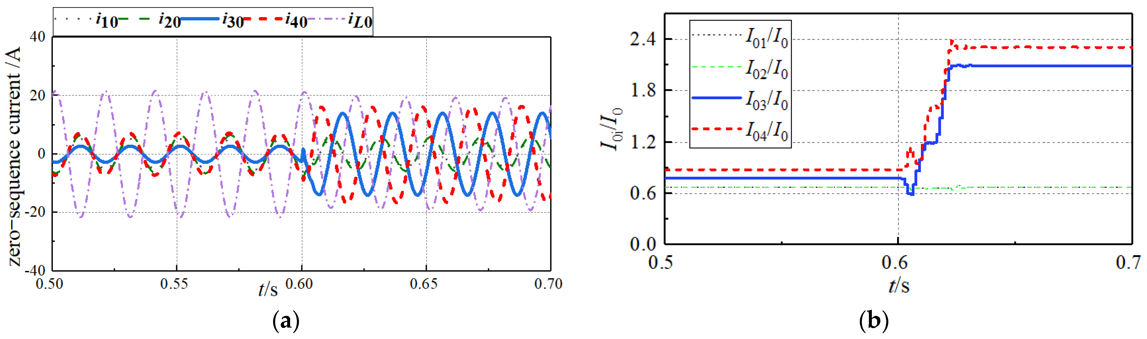
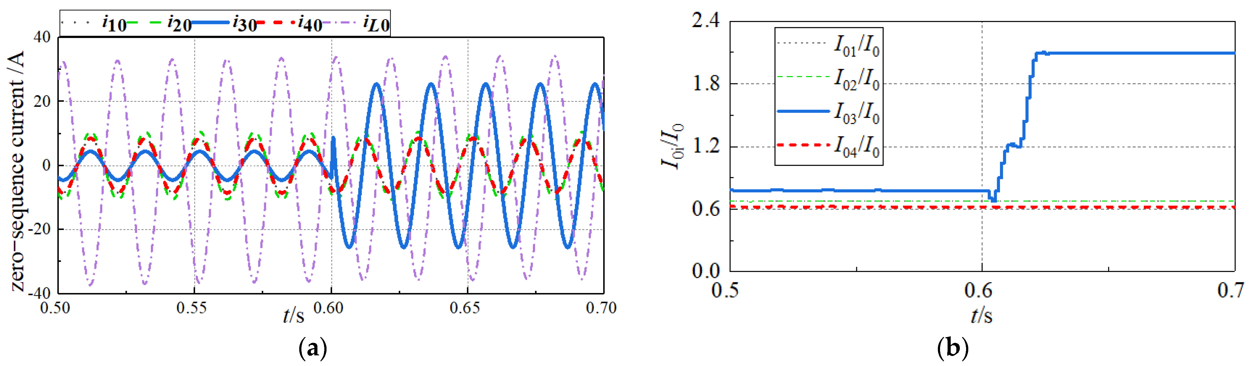
4.1. Different Fault Locations Simulation

(1) When a single-phase metallic grounding fault occurs at k2 in the simulation system as shown in Figure 4, the zero-sequence currents of each feeder and the zero-sequence currents of neutral line iL0 are depicted in Figure 6. Before and after RDG insertion, the zero-sequence currents of the feeders remain largely unchanged. Consequently, the FLS criterion Ki (as per the process in Figure 5) can be easily determined to be 0 by subtracting the values of Figure 6b before and after 0.6 s. Thus, the faulted line can be accurately identified as line3, which is precisely the modified line.
(2) When a metallic SPGF is at point k3, the zero-sequence currents of each feeder and the neutral point are shown in Figure 7. Before and after the RDG insertion, the zero-sequence currents of feeders line1 and line2 remain largely unchanged, while the current on line4 increases. Additionally, the zero-sequence current on modified line3 also notably increases. It is observed that the selection criterion Ki shows 2 nonzero values. According to the FLS process in Figure 5, the faulted line can be identified as non-modified line4, aligning with the zero-sequence current conditions of each feeder as described in Equations (4) and (10).
(3) When a metallic SPGF is at point k4, the zero-sequence currents of each feeder and the neutral point are depicted in Figure 8. Before and after RDG insertion, the zero-sequence currents of feeders line1, line2, and line4 remain largely unchanged, while the current on modified line3 significantly increases compared to other lines. At this point, the selection criterion Ki shows only 1 nonzero value. Following the FLS process in Figure 5, the faulted line can be identified as the main bus of the DNs. The zero-sequence current conditions of each feeder correspond to Equations (4) and (10).

4.2. Transient Impedance Tolerance Simulation

The simulation examines the accuracy of FLS results in the DNs when SPGF occurs at different positions and with varying transition resistances, as illustrated in Figure 4 and summarized in Table 3.
According to Table 3, the proposed FLS method accurately identifies faults even when the DNs encounter SPGFs with transition resistances as high as 2000 Ω, demonstrating robust tolerance to transition resistances.

4.3. Impact of RDG Size on FLS Results

To investigate the effect of RDG size on FLS accuracy, RDG values of 10 Ω, 100 Ω, and 300 Ω were configured in simulations. The system simulated an SPGF at position k2, and the FLS remained accurate under these conditions, as shown in Table 4.

5. Conclusions

This paper addresses the SPGF faut line selection issue in ADNs with NEVAEC. The proposed method involves modifying the grounding mode of transformers on the DG side from NPU to LRNG, which is activated after a fault occurs. This allows zero-sequence currents to form a path in the feeders during an SPGF. A FLS criterion Ki is established based on the difference in the ratio of zero-sequence current on each feeder to zero-sequence current on the neutral line before and after the LRNG is applied. The proposed method can accurately realize the fault line selection by using the characteristic of the transformer grounding mode modification, and the method is simple and practical.
The FLS logic is as follows: if all Ki (i = 1, 2, 3, …, j, …, m…) are zero, the modified line j is identified as having an SPGF. If non-zero values for Ki exist for both a modified line j and an unmodified line m, the SPGF is identified on the unmodified line m. If only one Ki is zero, the SPGF is identified on the ADNs bus.
The feasibility of the proposed method was validated through fault simulation analysis on the PSCAD platform. Accurate fault location is achieved by extracting steady-state fault characteristics over one power frequency cycle before and after the LRNG switch, with a simple implementation process. Simulation results indicate that the proposed method demonstrates strong tolerance to transition resistance (accurately identifying the faulted line even under a 2 kΩ transition resistance) and a simple extraction of fault characteristic signals. It is applicable based on the grounding mode modification of a single DG, the application scenario for more DGs with its grounding points in multi-feeder distribution system could be further investigated in future work.

Author Contributions

Conceptualization, S.S. and Q.X.; methodology, P.M. and Y.L.; software, B.L. and C.W.; validation, F.C. and J.Z.; formal analysis, S.S.; investigation, Q.X.; resources, P.M.; data curation, Y.L.; writing—original draft preparation, F.C. and C.W.; writing—review and editing, B.L. and J.Z.; visualization, S.S. and Q.X.; supervision, P.M. and Y.L.; project administration, S.S.; funding acquisition, S.S. All authors have read and agreed to the published version of the manuscript.

Funding

This research is supported by Yunnan Fundamental Research Projects (No. 202401CF070077).

Data Availability Statement

The original contributions presented in the study are included in the article, further inquiries can be directed to the corresponding author.

Conflicts of Interest

Authors Shi Su, Qingyang Xie, Pengfei Ma and Yuan Li were employed by the company Electric Power Research Institute of Yunnan Electric Power Grid Co., Ltd. The remaining authors declare that the research was conducted in the absence of any commercial or financial relationships that could be construed as a potential conflict of interest.

Abbreviations

PSCADPower Systems Computer Aided Design
DNsdistribution networks
NPUneutral point ungrounded
LRNGlow resistance neutral grounding
FGflexible grounding
NEVAECneutral earthing via arc extinguishing coil
SPGFsingle-phase ground faults
FLSfault line selection
DGsdistributed generations
ADNsactive distribution networks
RMSRoot Mean Square

References

  1. Su, X.; Wei, H. A Fault-Line Selection Method for Small-Current Grounded System Based on Deep Transfer Learning. Energies 2022, 15, 3467. [Google Scholar] [CrossRef]
  2. Zhang, M.; Luan, W.; Ai, X.; Xu, B. Single-phase Grounding Fault Detection in Non-solidly Earthed Network Based on Negative Sequence Characteristics of Low-voltage Side. Power Syst. Technol. 2024, 48, 1654–1662. [Google Scholar]
  3. Zou, C.; Liu, D.; Lin, B.; Lu, Y.; Liu, J. Single-phase Ground Fault Location of Distribution Network with Distributed Generator Based on Characteristic Energy and BFAGA. High Volt. Eng. 2024, 50, 2706–2715. [Google Scholar]
  4. Qian, H.; Huang, Z.; Ruan, D. Single phase-to-earth fault location of small current grounding system with distributed generation. Electr. Mach. Control 2014, 18, 17–23. [Google Scholar]
  5. Xue, Y.; Guo, L.; Zhang, L.; Xu, B.; Li, T. Selection Problems of Neutral Grounding Mode in Active Distribution Networks. Autom. Electr. Power Syst. 2015, 39, 129–136. [Google Scholar]
  6. Ren, X.; Bai, Y.; Dai, Y.; Liang, R.; Gao, H.; Su, L.; Zhang, X.; Kong, L.; Zhang, P. Research on The Countermeasures of The Single-Phase-to-Earth Faults in Flexibly Grounded Distribution Networks. Alex. Eng. J. 2024, 98, 68–79. [Google Scholar] [CrossRef]
  7. Tian, J.; Li, H.; Jiang, L.; Shen, Z.; Ren, H.; Guo, L. Analysis of Single-phase Grounding Fault Characteristics of Low Resistance Grounding System with Multi-Distributed Power Supply. Power Syst. Prot. Control 2024, 52, 103–110. [Google Scholar]
  8. Shao, W.; Bai, J.; Cheng, Y.; Zhang, Z.; Li, N. Research on a Faulty Line Selection Method Based on the Zero-Sequence Disturbance Power of Resonant Grounded Distribution Networks. Energies 2019, 12, 846. [Google Scholar] [CrossRef]
  9. Norshahrani, M.; Mokhlis, H.; Abu Bakar, A.H.; Jamian, J.J.; Sukumar, S. Progress on Protection Strategies to Mitigate the Impact of Renewable Distributed Generation on Distribution Systems. Energies 2017, 10, 1864. [Google Scholar] [CrossRef]
  10. Cui, Q.; El-Arroudi, K.; Weng, Y. A Feature Selection Method for High Impedance Fault Detection. IEEE Trans. Power Deliv. 2019, 34, 1203–1215. [Google Scholar] [CrossRef]
  11. He, Y.; Zhang, X.; Wu, W.; Zhang, J.; Bai, W.; Guo, A.; Chen, Y. Faulty Line Selection Method Based on Comprehensive Dynamic Time Warping Distance in a Flexible Grounding System. Energies 2022, 15, 471. [Google Scholar] [CrossRef]
  12. Wang, W.; Gao, X.; Fan, B.; Zeng, X.; Yao, G. Faulty Phase Detection Method Under Single-Line-to-Ground Fault Considering Distributed Parameters Asymmetry and Line Impedance in Distribution Networks. IEEE Trans. Power Deliv. 2022, 37, 1513–1522. [Google Scholar] [CrossRef]
  13. Zhang, P.; Jin, M.; Liang, R.; Tang, Z.; Hou, M.; Peng, N.; Li, J. Faulty Cable Segment Identification of Low-Resistance Grounded Active Distributions via Grounding Wire Current-Based Approach. IEEE Trans. Ind. Inform. 2024, 20, 7708–7718. [Google Scholar] [CrossRef]
  14. Li, J.; Bi, H.; Li, C.; Li, J.; Zeng, D.; Wang, G. Analysis and calculation method for multiple faults in low-resistance grounded systems with inverter-interfaced distributed generators based on a PQ control strategy. Int. J. Electr. Power Energy Syst. 2022, 138, 0142–0615. [Google Scholar] [CrossRef]
  15. Chen, X.; Yuan, S.; Li, Y.; Li, Z.; Wang, Q.; Geng, S. Analysis of single-phase grounding fault characteristics in petal-shaped distribution network with inverter-interfaced distributed generator. Electr. Power Autom. Equip. 2022, 42, 129–137. [Google Scholar]
  16. Kim, C.H.; Aggarwal, R.K. Closure on “a novel fault detection technique of high impedance arcing faults in transmission lines using the wavelet transform”. IEEE Trans. Power Deliv. 2003, 18, 1596–1597. [Google Scholar] [CrossRef]
  17. Park, S.; Sung, E.-T.; Wang, S.; Hong, S. Mixer-Free Phase and Amplitude Comparison Method for Built-in Self- Test of Multiple Channel Beamforming IC. In Proceedings of the 2023 IEEE Radio Frequency Integrated Circuits Symposium (RFIC), San Diego, CA, USA, 11–13 June 2023; pp. 265–268. [Google Scholar]
  18. Cong, Z.; Liu, Y.; Fang, J.; Wang, P.; Guo, L.; Jiang, X. Root-Cause Identification of Single Line-to-Ground Fault in Urban Small Current Grounding Systems Based on Correlation Dimension and Average Resistance. IEEE Trans. Power Deliv. 2020, 35, 1834–1843. [Google Scholar] [CrossRef]
  19. He, R.; Hu, Z.; Wang, T. A Fault Line Selection Method for Resonant Grounding System Considering Injected Harmonics of Distributed Generation. Power Syst. Technol. 2019, 43, 670–680. [Google Scholar]
  20. Yuan, J.; Li, X.; Zhang, Z. Research on single-phase grounding fault selection technology for active distribution network based on injected signal. Electr. Meas. Instrum. 2020, 57, 44–49. [Google Scholar]
  21. Wang, P.; Xu, B.; Chen, H.; Wang, W.; Liang, D.; Sun, Z. Influence of Error of Zero-sequence Current Transformer on Small-current High-resistance Grounding Protection and Type Selection. Autom. Electr. Power Syst. 2023, 47, 154–162. [Google Scholar]
  22. Pirmani, S.; Fernando, W.; Mahmud, M. Single line-to-ground fault current analysis for resonant grounded power distribution networks in bushfire prone areas. Electr. Power Syst. Res. 2024, 237, 110883. [Google Scholar] [CrossRef]
  23. Wang, Y.; Chen, Q.; Zeng, X.; Huang, X.; Song, Q. Faulty Feeder Detection Based on Space Relative Distance for Compensated Distribution Network with IIDG Injections. IEEE Trans. Power Deliv. 2021, 36, 2459–2466. [Google Scholar] [CrossRef]
Figure 1. Diagram of a 10 kV DNs with DGs.
Energies 17 04743 g001
Figure 2. Zero-sequence equivalent circuit for a SPGF in a 10 kV DNs.
Energies 17 04743 g002
Figure 3. Diagram of the modified 10 kV DNs.
Energies 17 04743 g003
Figure 4. Zero-sequence equivalent circuit for a SPGF in the 10 kV DNs after modification.
Energies 17 04743 g004
Figure 5. Flowchart of the proposed FLS method.
Energies 17 04743 g005
Figure 6. Metallic single-phase ground fault on modified line3 (a) Zero-sequence currents of each line; (b) Ratio of zero-sequence currents between feeders and neutral point.
Energies 17 04743 g006
Figure 7. Metallic single-phase ground fault on non-modified line4 (a) Zero-sequence currents of each line; (b) Ratio of zero-sequence currents between feeders and neutral point.
Energies 17 04743 g007
Figure 8. Metallic single-phase ground fault on bus (a) Zero-sequence currents of each line; (b) Ratio of zero-sequence currents between feeders and neutral point.
Energies 17 04743 g008
Table 1. FLS criteria.
SituationCriterion CharacteristicsSPGF Location
1All Ki are zeroThe modified line
2One Ki is non-zeroThe bus
3Two Ki is non-zeroThe non-modified line among the two non-zero lines
Table 2. Line model parameters.
Line TypeResistance (Ω/km)Inductance (mH/km)Capacitance (μF/km)
Positive SequenceZero
Sequence
Positive
Sequence
Zero
Sequence
Positive
Sequence
Zero
Sequence
Cable0.272.70.2551.1090.3760.276
Overhead line0.170.321.0173.560.1150.0062
Table 3. FLS results with different transition resistances for SPGF.
Fault
Location
Transition
Resistance/Ω
K1K2K3K4Selection Result
k10¬ 00¬ 00Line1
200¬ 00¬ 00Line1
1000¬ 00¬ 00Line1
2000¬ 00¬ 00Line1
k200000Line3
2000000Line3
10000000Line3
20000000Line3
k3000¬ 0¬ 0Line4
20000¬ 0¬ 0Line4
100000¬ 0¬ 0Line4
200000¬ 0¬ 0Line4
k4000¬ 00Bus
20000¬ 00Bus
100000¬ 00Bus
200000¬ 00Bus
Table 4. FLS results with different RDG values (fault happens at k2).
RDGK1K2K3K4Selection Result
100000Line3correct result
1000000Line3correct result
3000000Line3correct result
Disclaimer/Publisher’s Note: The statements, opinions and data contained in all publications are solely those of the individual author(s) and contributor(s) and not of MDPI and/or the editor(s). MDPI and/or the editor(s) disclaim responsibility for any injury to people or property resulting from any ideas, methods, instructions or products referred to in the content.

