

Coordinated Control of Transient Voltage Support in Doubly Fed Induction Generators

Abstract
:1. Introduction
2. Transient Operation Analysis of DFIG Grid Connection
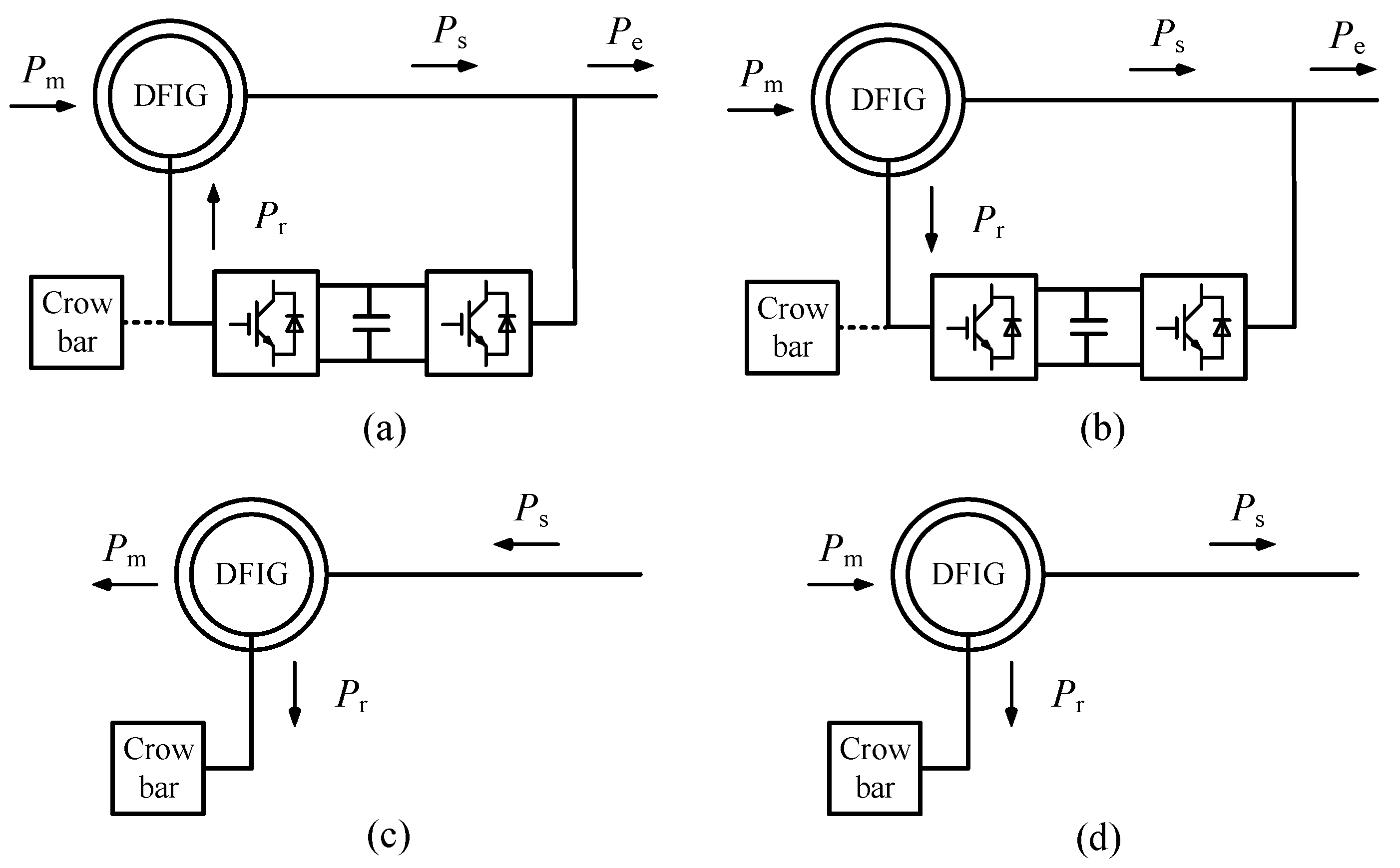
2.1. Transient Operation Characteristics of DFIG
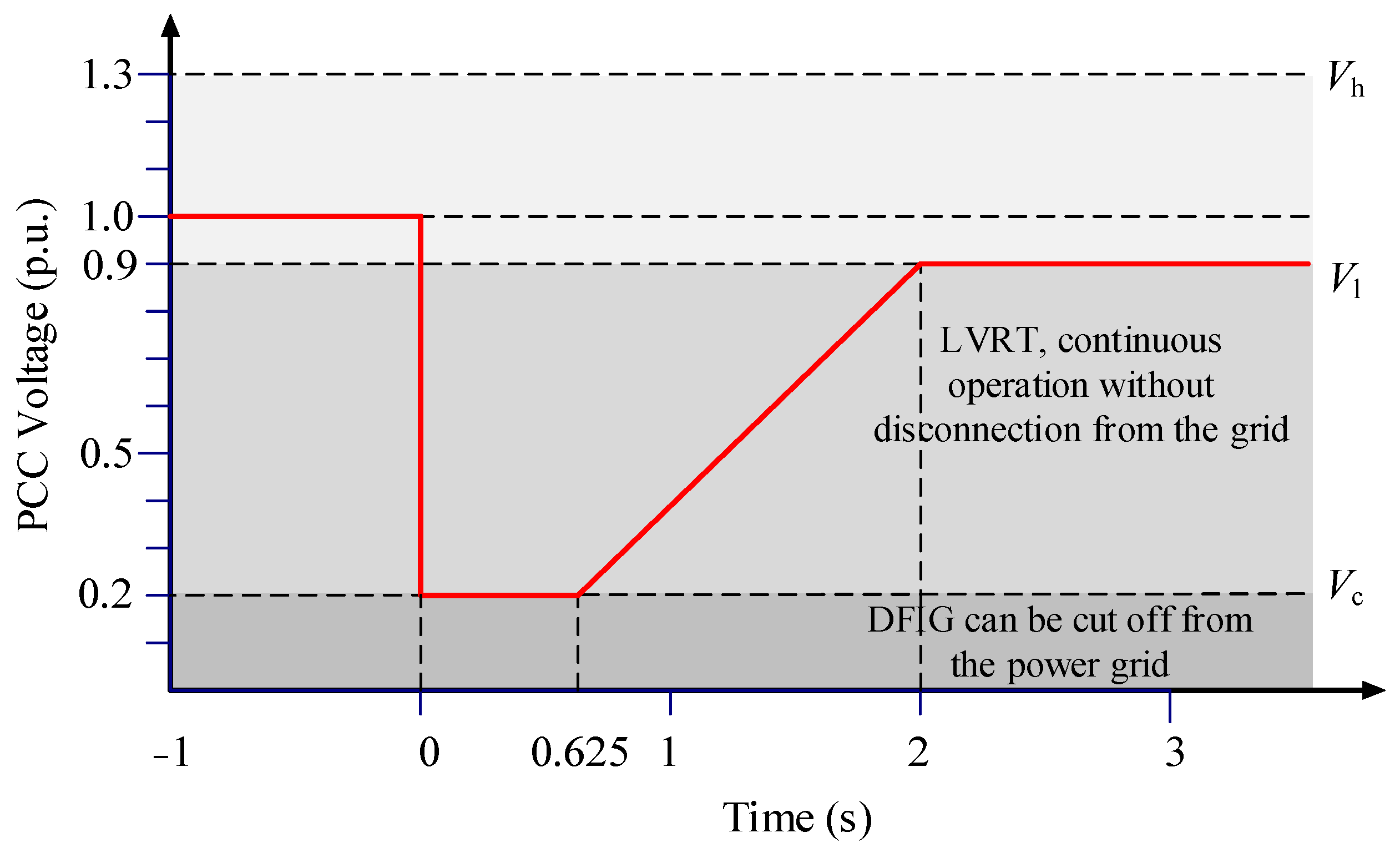
2.2. Transient Operational Control Objectives
3. Cooperative Control Method for Transient Voltage Support
3.1. Additional Stator Current Demagnetization Control
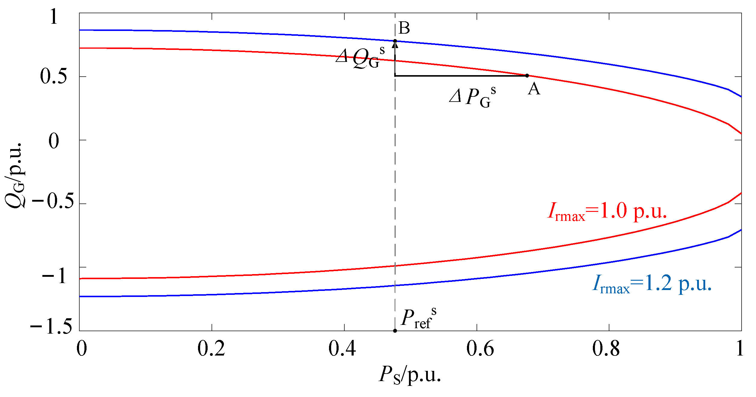
3.2. DFIG Reactive Power Control Based on Voltage Reactive Power Sensitivity Matrix
3.3. Transient Active and Reactive Power Joint Control
4. Doubly Fed Wind Farm Transient Voltage Support Coordination Control Process
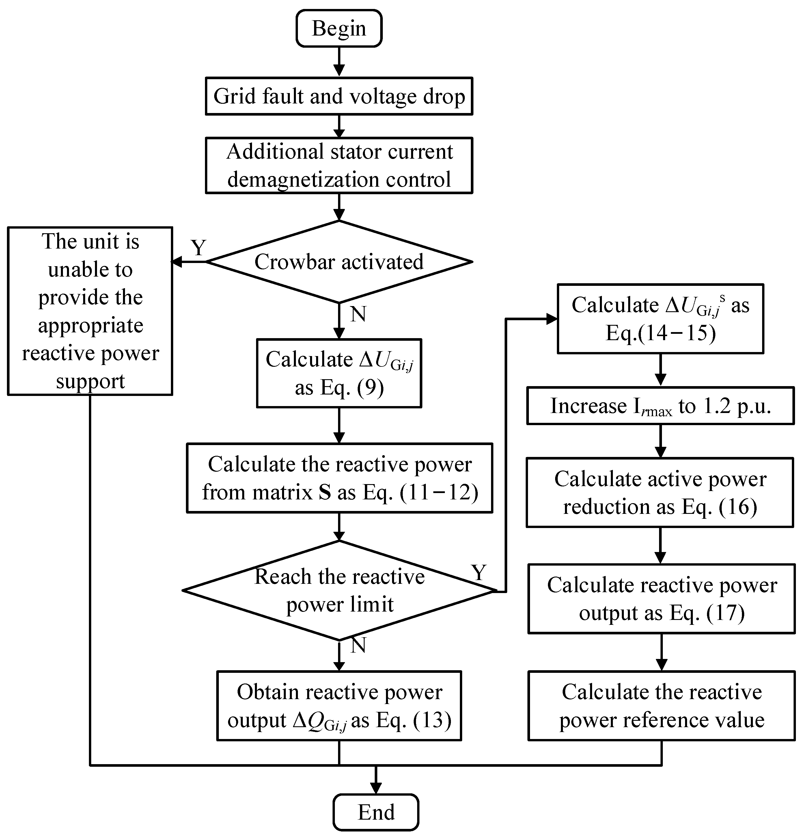
- (1)
- Step 1: When a power grid failure occurs, the voltage at the wind farm connection point drops. The additional stator current demagnetization control acts first to suppress the rotor current, reducing the number of units that trigger the crowbar protection action and ensuring that the power of as many units as possible is controllable during the transient process.Afterward, if the crowbar protection is activated, the unit will still be unable to provide corresponding reactive power support, and the unit will be uncontrollable during the transient period. If crowbar protection does not operate, the control strategy proceeds to step 2.
- (2)
- Step 2: The computer terminal voltage control target increment is calculated according to Equation (9). Next, the sensitivity matrix is calculated offline according to Equations (11) and (12) to obtain the reactive output increment of the DFIG during the transient period. If the current unit does not reach the reactive power output limit, the reactive power output increment is calculated, and the reactive power output is formed proportionally to achieve transient support. If the current unit reaches the reactive power output limit, the control strategy proceeds to step 3.
- (3)
- Step 3: When the reactive power output of the unit does not reach its limit, the voltage at the computer terminal rises as shown in Equation (13). When the reactive power output of the unit reaches the limit, voltage support is carried out according to the joint control of active and reactive power. At this time, the reactive power output of the unit can be calculated according to Equations (14)–(17).
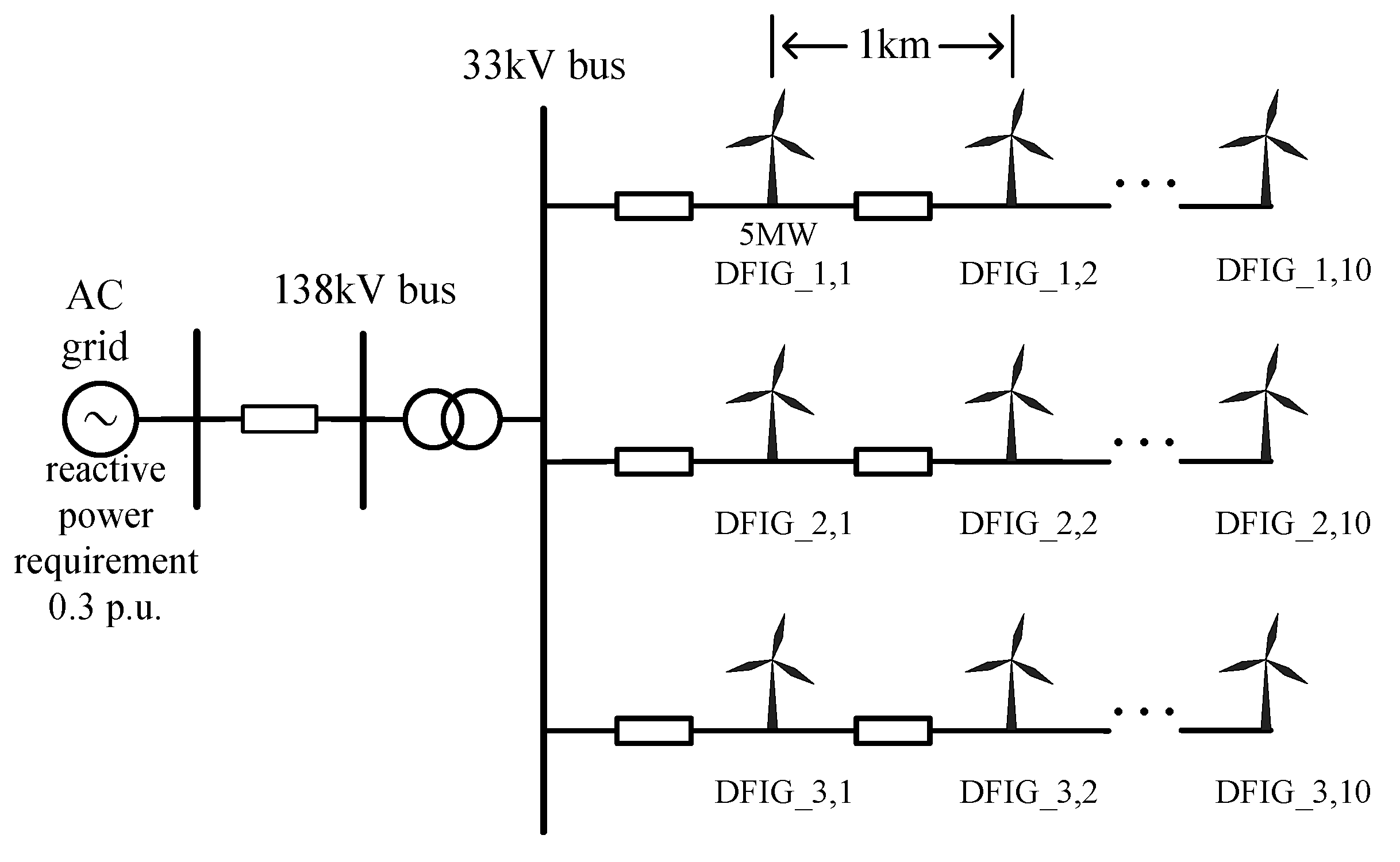
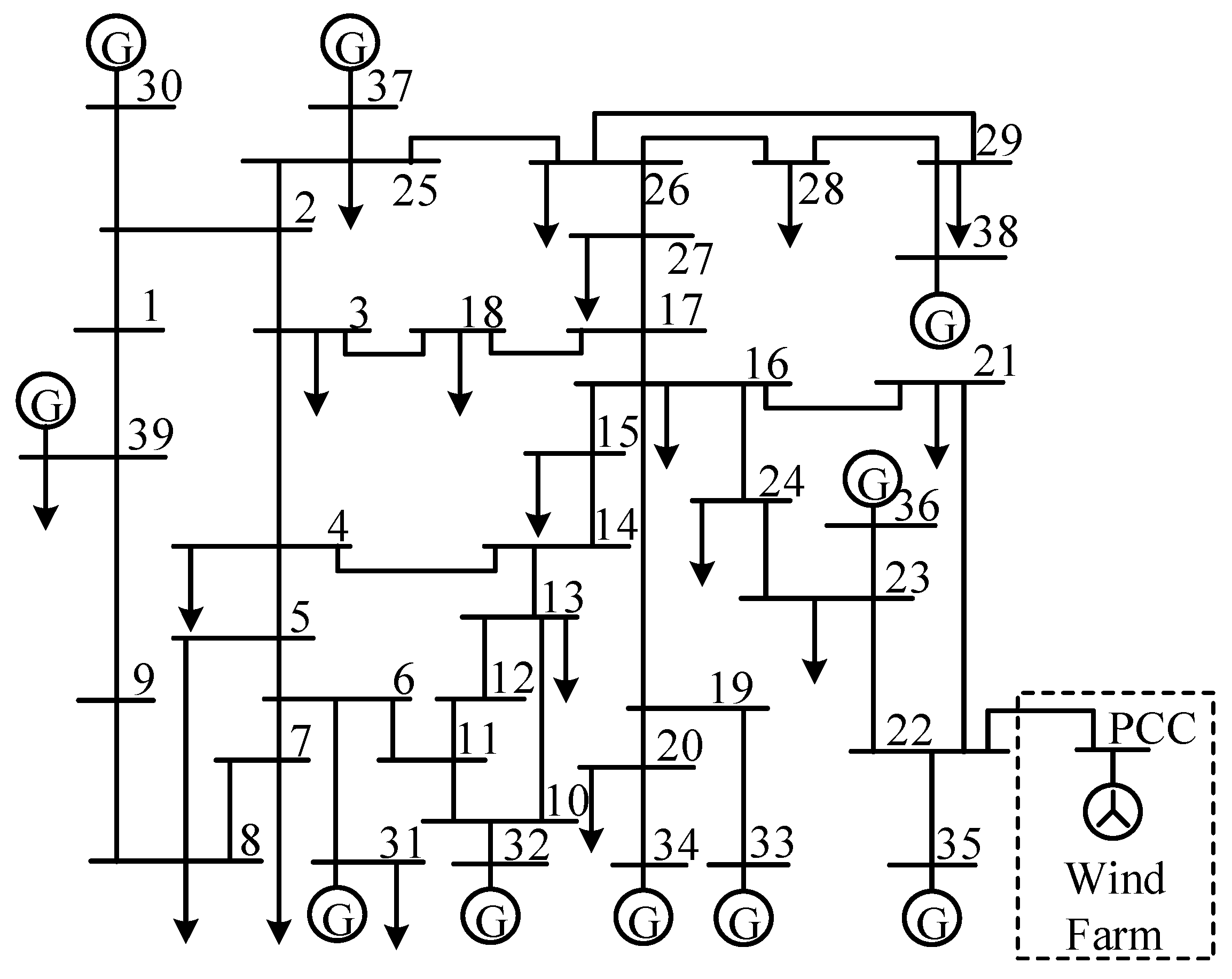
5. Simulation
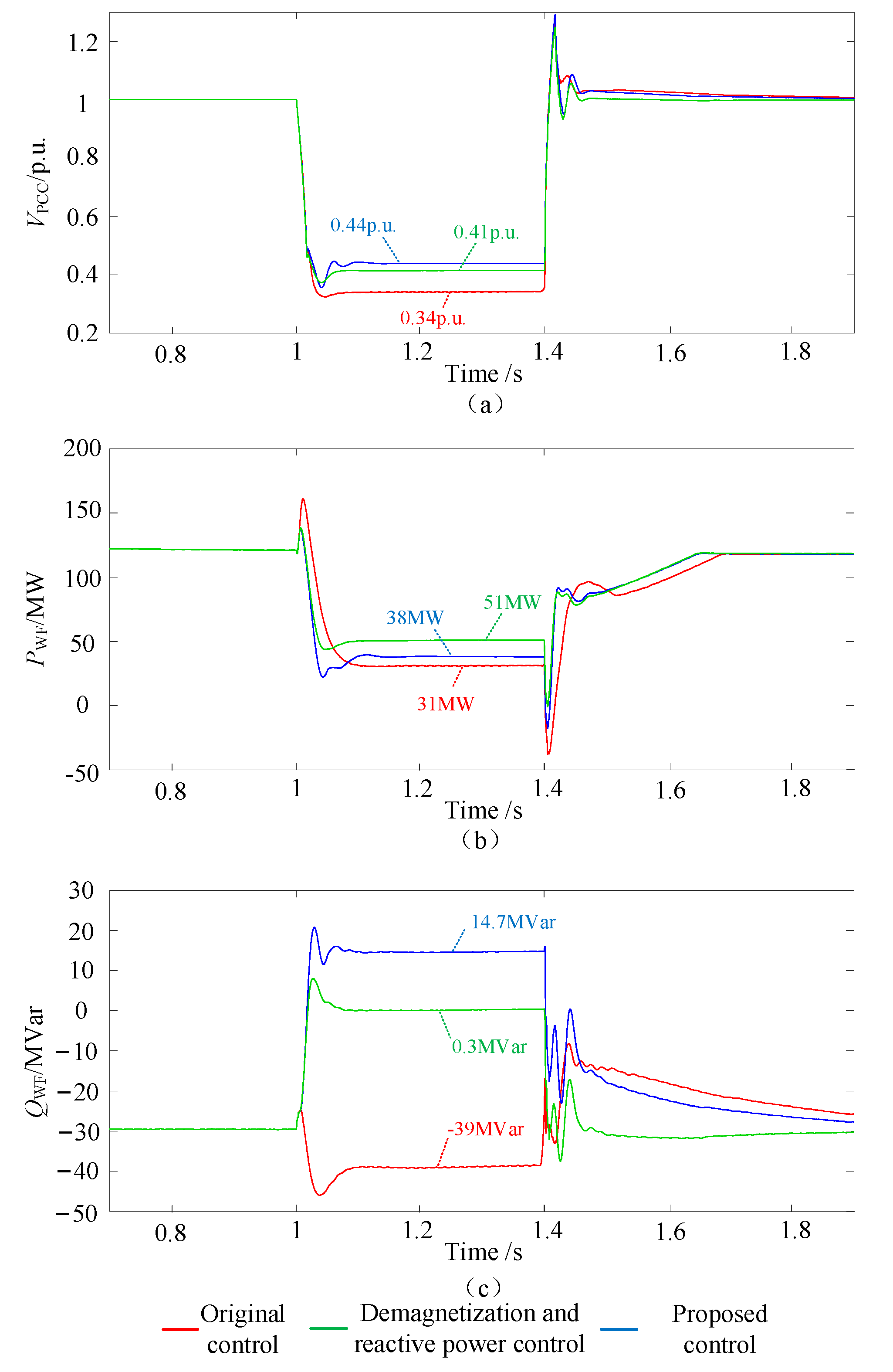
5.1. Case I
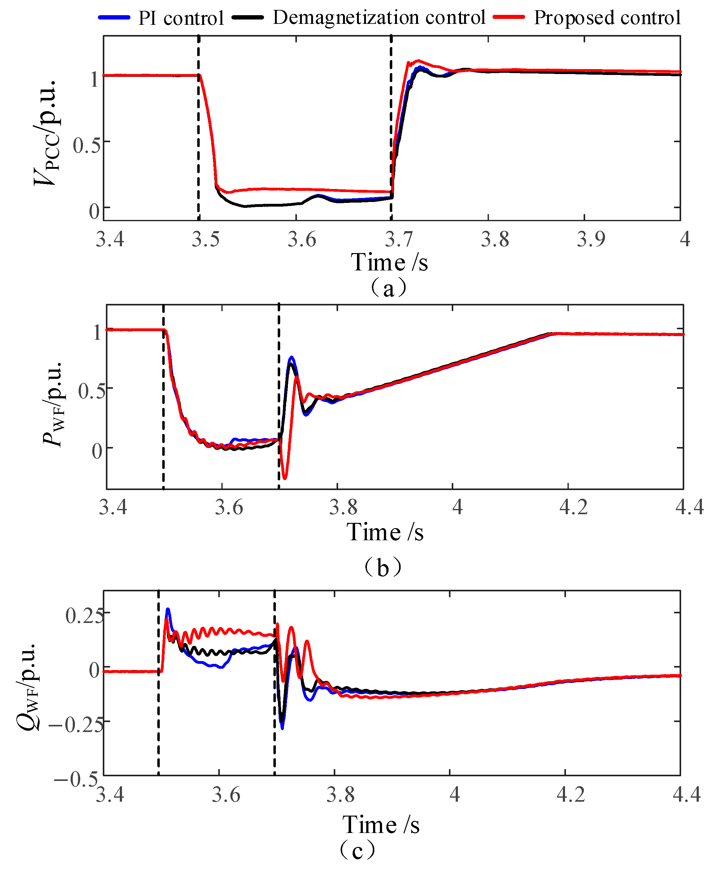
5.1.1. The PCC Point Voltage Dropped to 0.35 p.u.
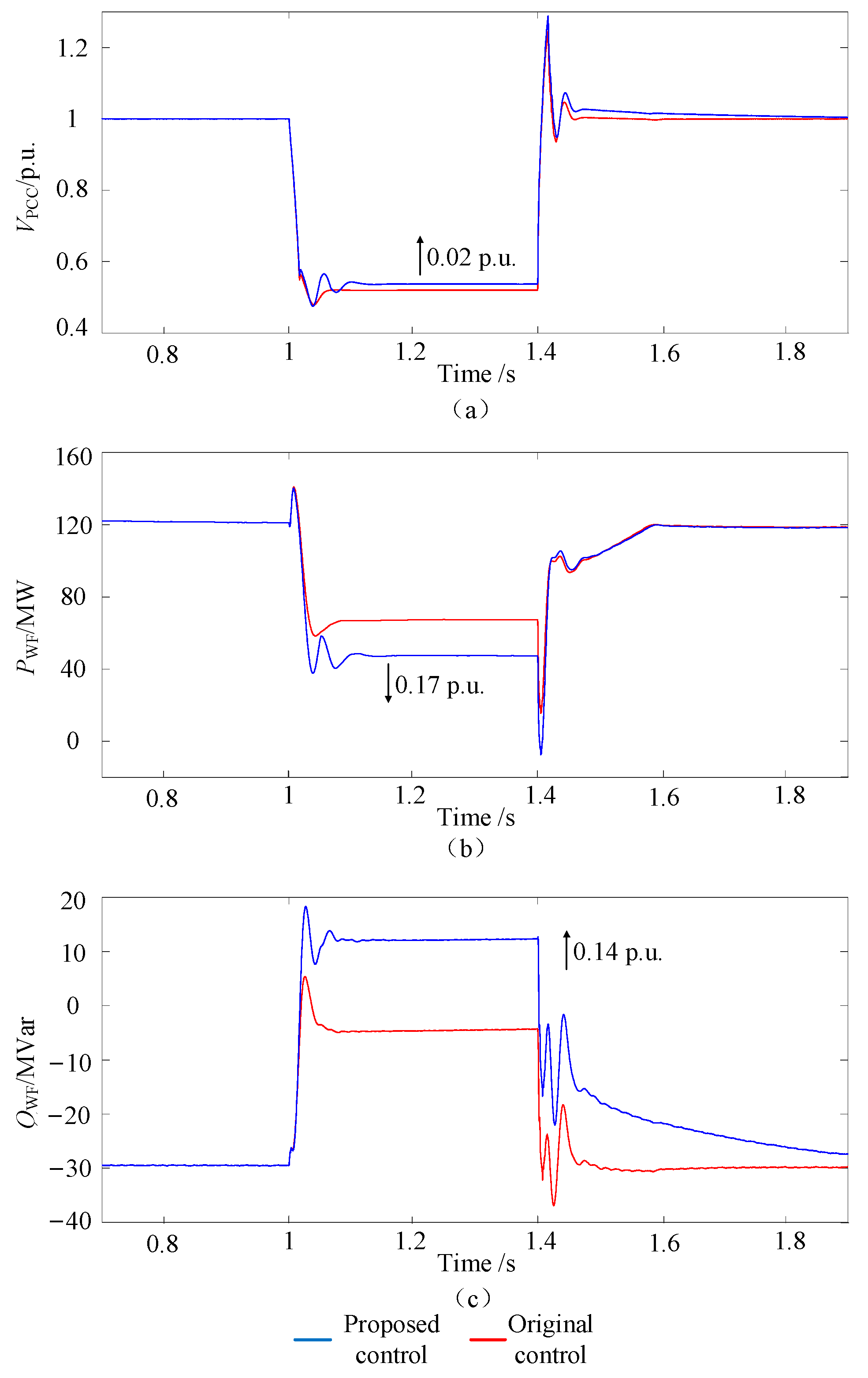
5.1.2. The PCC Point Voltage Dropped to 0.5 p.u.
- ①
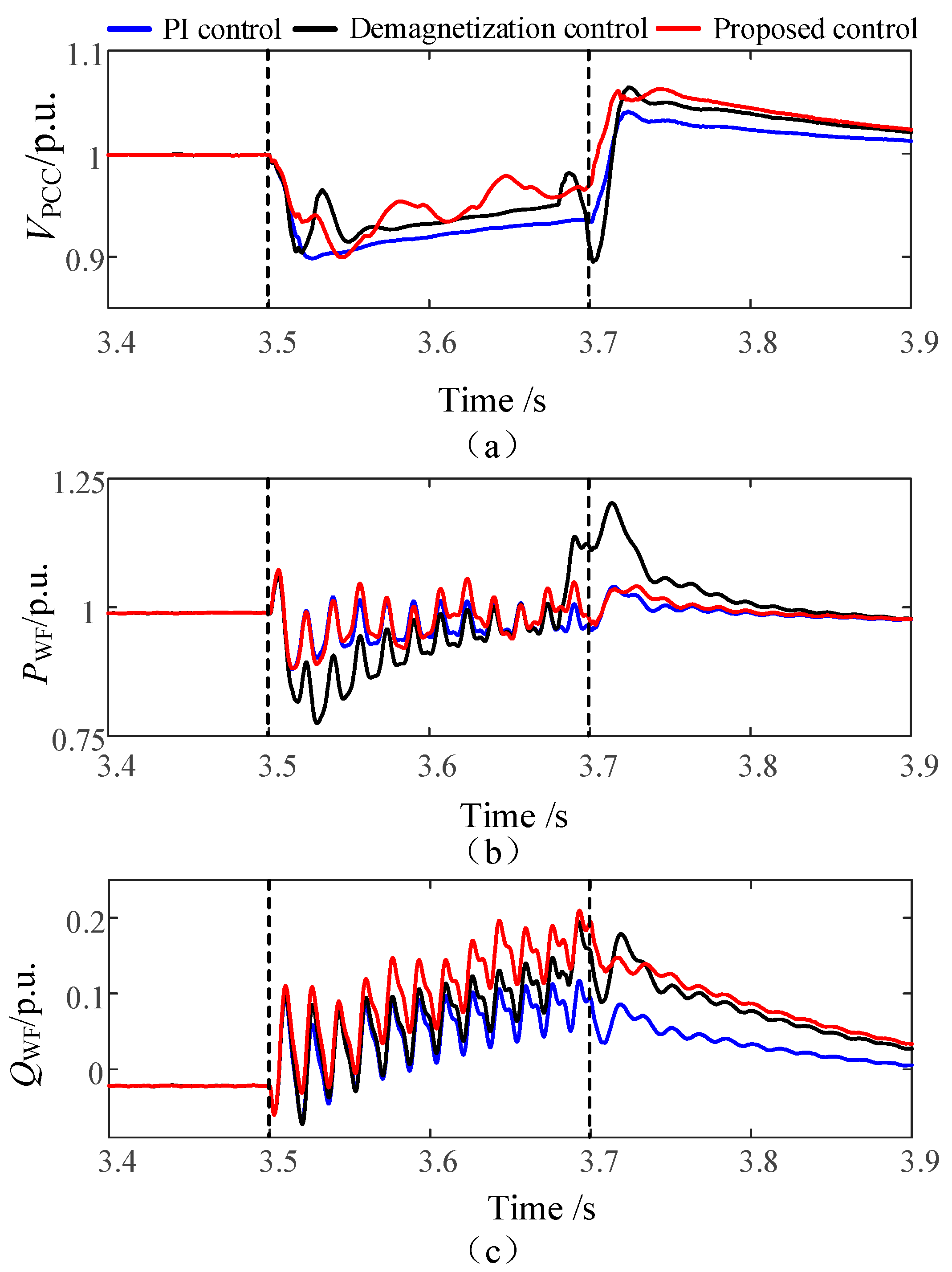
- Transient voltage support verification
- ②
- Coordinated reactive power control verification
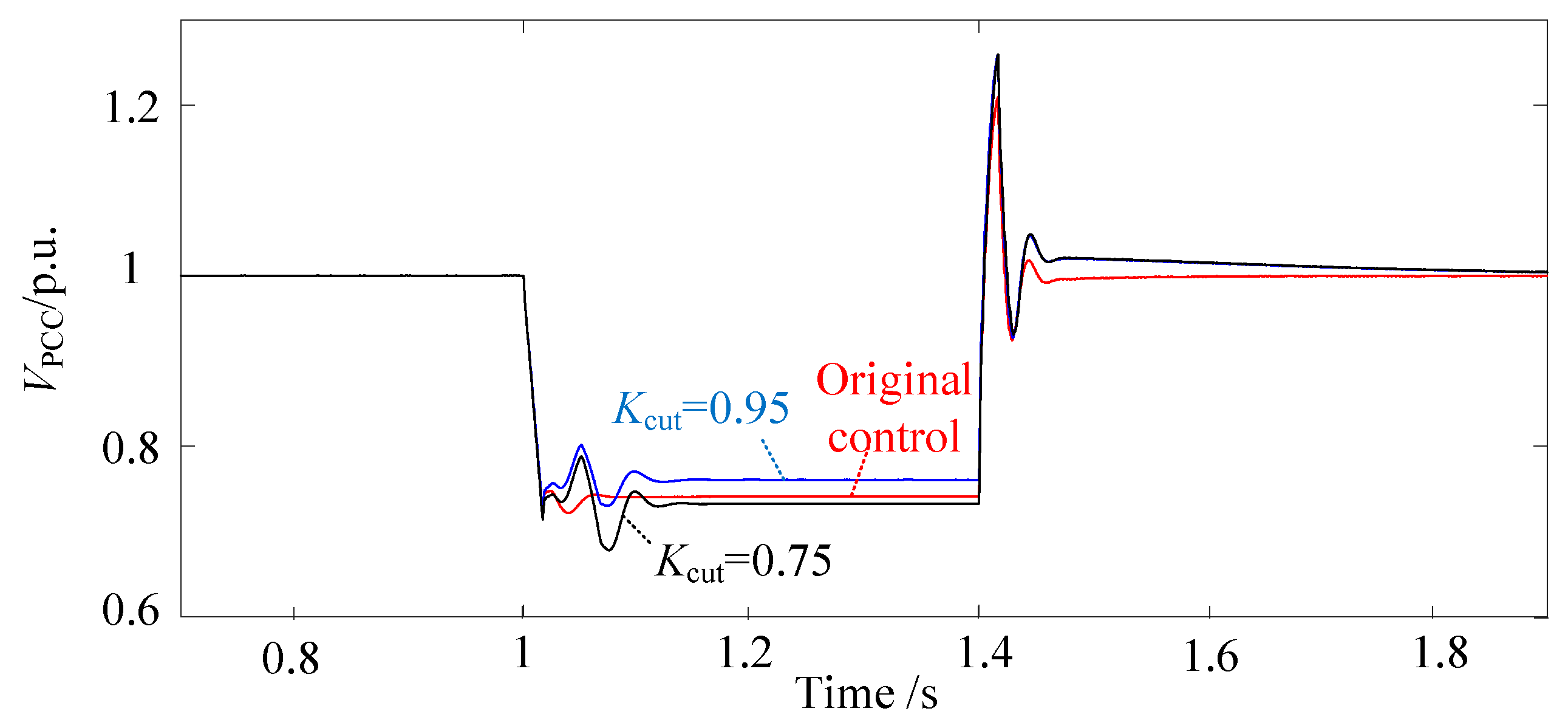
5.1.3. The PCC Point Voltage Dropped to 0.75 p.u.
- ①
- Transient voltage support verification
- ②
- Influence of P-V droop active power reduction coefficient
5.2. Case II
5.2.1. The PCC Point Voltage Dropped Symmetrically to 0.9 p.u.
5.2.2. The PCC Point Voltage Dropped Symmetrically to 0.6 p.u.
5.2.3. Asymmetric Voltage Drop of PCC
6. Conclusions
Author Contributions
Funding
Data Availability Statement
Conflicts of Interest
References
- Global Wind Energy Council (GWEC). Global Wind Report: Annual Market Update 2015; GWEC: Brussels, Belgium, 2016. [Google Scholar]
- Guo, W.; Xiao, L.; Dai, S.; Li, Y.; Xu, X.; Zhou, W.; Li, L. LVRT capability enhancement of DFIG with switch type fault current limiter. IEEE Trans. Ind. Electron. 2015, 62, 332–342. [Google Scholar] [CrossRef]
- Hoseinzadeh, B.; Bak, C.L. Admittance modeling of voltage and current controlled inverter for harmonic instability studies. In Proceedings of the 2016 IEEE Power and Energy Society General Meeting (PESGM), Boston, MA, USA, 17–21 July 2016; pp. 1–5. [Google Scholar]
- Schauder, C. Impact of FERC 661-A and IEEE 1547 on photovoltaic inverter designIn. In Proceedings of the 2011 IEEE Power and Energy Society General Meeting, Detroit, MI, USA, 24–28 July 2011; pp. 1–6. [Google Scholar]
- Debouza, M.; Al-Durra, A. Grid ancillary services from doubly fed induction generator-based wind energy conversion system: A review. IEEE Access 2019, 7, 7067–7081. [Google Scholar] [CrossRef]
- Verma, N.; Kumar, N.; Gupta, S.; Malik, H.; Márquez, F.P.G. Review of sub-synchronous interaction in wind integrated power systems: Classification, challenges, and mitigation techniques. Prot. Control Mod. Power Syst. 2023, 8, 1–26. [Google Scholar] [CrossRef]
- Mahela, O.P.; Gupta, N.; Khosravy, M.; Patel, N. Comprehensive Overview of Low Voltage Ride Through Methods of Grid Integrated Wind Generator. IEEE Access 2019, 7, 99299–99326. [Google Scholar] [CrossRef]
- Naderi, S.B.; Negnevitsky, M.; Muttaqi, K.M. A Modified DC Chopper for Limiting the Fault Current and Controlling the DC-Link Voltage to Enhance Fault Ride-Through Capability of Doubly-Fed Induction-Generator-Based Wind Turbine. IEEE Trans. Ind. Appl. 2019, 55, 2021–2032. [Google Scholar] [CrossRef]
- Ren, J.; Xiao, X.; Zheng, Z.; Wang, Y.; Ma, Z.; Liu, K. Impact of Phase Angle Jump on DFIG Under LVRT Conditions: Challenges and Recommendations. IEEE Trans. Power Deliv. 2021, 36, 3701–3713. [Google Scholar] [CrossRef]
- Haidar, A.M.A.; Muttaqi, K.M.; Hagh, M.T. A Coordinated Control Approach for DC link and Rotor Crowbars to Improve Fault Ride-Through of DFIG-Based Wind Turbine. IEEE Trans. Ind. Appl. 2017, 53, 4073–4086. [Google Scholar] [CrossRef]
- Benali, A.; Khiat, M.; Allaoui, T.; Denaï, M. Power Quality Improvement and Low Voltage Ride Through Capability in Hybrid Wind-PV Farms Grid-Connected Using Dynamic Voltage Restorer. IEEE Access 2018, 6, 68634–68648. [Google Scholar] [CrossRef]
- Flannery, P.S.; Venkataramanan, G. A Fault Tolerant Doubly Fed Induction Generator Wind Turbine Using a Parallel Grid Side Rectifier and Series Grid Side Converter. IEEE Trans. Power Electron. 2008, 23, 1126–1135. [Google Scholar] [CrossRef]
- Ghosh, S.; Bhattarai, R.; Kamalasadan, S. Reactive power estimation based adaptive voltage control for improved grid voltage restoration using doubly fed induction generators. In Proceedings of the 2017 IEEE Transportation Electrification Conference (ITEC-India), Pune, India, 13–15 December 2017; pp. 1–5. [Google Scholar]
- Ma, S.; Geng, H.; Liu, L.; Yang, G.; Pal, B.C. Grid-Synchronization Stability Improvement of [9] Large Scale Wind Farm During Severe Grid Fault. IEEE Trans. Power Syst. 2018, 33, 216–226. [Google Scholar]
- Ghosh, S.; Isbeih, Y.J.; Bhattarai, R.; Moursi, M.S.E.; El-Saadany, E.F.; Kamalasadan, S. A Dynamic Coordination Control Architecture for Reactive Power Capability Enhancement of the DFIG-Based Wind Power Generation. IEEE Trans. Power Syst. 2020, 35, 3051–3064. [Google Scholar] [CrossRef]
- Nasiri, M.R.; Farhangi, S.; Rodríguez, J. Model Predictive Control of a Multilevel CHB STATCOM in Wind Farm Application Using Diophantine Equations. IEEE Trans. Ind. Electron. 2019, 66, 1213–1223. [Google Scholar] [CrossRef]
- Souxes, T.; Parasidis, A.; Vournas, C.D. Stabilizing Controls for Wind Generators Participating in Transmission V/Q Support. IEEE Trans. Power Syst. 2020, 35, 3627–3635. [Google Scholar] [CrossRef]
- Lyu, X.; Jia, Y.; Liu, T.; He, Y. Concurrent Optimal Re/Active Power Control for Wind Farms Under Low-Voltage-Ride-Through Operation. IEEE Trans. Power Syst. 2020, 35, 4956–4959. [Google Scholar] [CrossRef]
- Zhao, C.; Sun, D.; Zhang, L.; Nian, H.; Hu, B. Two-Stage Optimal Re/Active Power Control of Large-Scale Wind Farm to Mitigate Voltage Dip Induced Frequency Excursion. IEEE Trans. Sustain. Energy 2023, 14, 730–733. [Google Scholar] [CrossRef]
- Kim, J.; Seok, J.-K.; Muljadi, E.; Kang, Y.C. Adaptive Q–V Scheme for the Voltage Control of a DFIG-Based Wind Power Plant. IEEE Trans. Power Electron. 2016, 31, 3586–3599. [Google Scholar] [CrossRef]
- Kim, J.; Muljadi, E.; Park, J.-W.; Kang, Y.C. Flexible IQ–V Scheme of a DFIG for Rapid Voltage Regulation of a Wind Power Plant. IEEE Trans. Ind. Electron. 2017, 64, 8832–8842. [Google Scholar] [CrossRef]
- Han, H.; Li, Z.; Wang, H.; Feng, Q.; Guo, R.; Yang, Z.; Liu, X. Design of a Parallel All-DC Wind Power System with Turbine-Side Boost Based on a New DC Conversion. IEEE Access 2024, 12, 3054–3069. [Google Scholar] [CrossRef]
- Thapa, K.B.; Jayasawal, K.; Khatri, P. Enhanced Low Voltage Ride- Through Control Capability of a DFIG-Based Wind Power Plant. In Proceedings of the 2020 IEEE International Conference on Power Systems Technology (POWERCON), Bangalore, India, 14–16 September 2020; pp. 1–6. [Google Scholar]
- Tong, N.; Lin, X.; Li, Z.; Fang, J.; Zhuo, Y.; Sui, Q.; Jin, N.; Chen, Z.; Muradov, N. Coordinated Sequential Control of Individual Generators for Large-Scale DFIG-Based Wind Farms. IEEE Trans. Sustain. Energy 2020, 11, 1679–1692. [Google Scholar] [CrossRef]
- GB/T 19963-2011; Technical Regulations for Wind Farm Integration into the Power Grid. China Electric Power Research Institute: Beijing, China, 2011.
- Zhou, L.; Liu, J.; Zhou, S. Improved Demagnetization Control of a Doubly-Fed Induction Generator Under Balanced Grid Fault. IEEE Trans. Power Electron. 2015, 30, 6695–6705. [Google Scholar] [CrossRef]


| Parameters | Value |
|---|---|
| Baseline capacity | 150 MVA |
| DFIG rated capacity | 5 MVA |
| Rated frequency | 60 Hz |
| Feeder reference voltage | 33 kV |
| AC grid rated voltage | 138 kV |
| Collector circuit resistance | 0.0034 p.u./km |
| Collector line reactance | 0.0048 p.u./km |
| Spacing between units | 1 km |
Disclaimer/Publisher’s Note: The statements, opinions and data contained in all publications are solely those of the individual author(s) and contributor(s) and not of MDPI and/or the editor(s). MDPI and/or the editor(s) disclaim responsibility for any injury to people or property resulting from any ideas, methods, instructions or products referred to in the content. |
© 2024 by the authors. Licensee MDPI, Basel, Switzerland. This article is an open access article distributed under the terms and conditions of the Creative Commons Attribution (CC BY) license (https://creativecommons.org/licenses/by/4.0/).
Share and Cite
Xu, G.; Qiu, J.; Zhang, J.; Yang, H.; Gao, Q.; Jiang, T.; Wang, Y. Coordinated Control of Transient Voltage Support in Doubly Fed Induction Generators. Energies 2024, 17, 4763. https://doi.org/10.3390/en17194763
Xu G, Qiu J, Zhang J, Yang H, Gao Q, Jiang T, Wang Y. Coordinated Control of Transient Voltage Support in Doubly Fed Induction Generators. Energies. 2024; 17(19):4763. https://doi.org/10.3390/en17194763
Chicago/Turabian StyleXu, Guanghu, Jian Qiu, Jianxin Zhang, Huanhuan Yang, Qin Gao, Tuo Jiang, and Yuan Wang. 2024. "Coordinated Control of Transient Voltage Support in Doubly Fed Induction Generators" Energies 17, no. 19: 4763. https://doi.org/10.3390/en17194763