Article

Pore-Scale Mechanism Analysis of Enhanced Oil Recovery by Horizontal Well, Dissolver, Nitrogen, and Steam Combined Flooding in Reducer Systems with Different Viscosities for Heavy Oil Thermal Recovery

School of Civil and Resource Engineering, University of Science and Technology Beijing, Beijing 100083, China
*
Author to whom correspondence should be addressed.
Energies 2024, 17(19), 4783; https://doi.org/10.3390/en17194783
Submission received: 23 August 2024 / Revised: 15 September 2024 / Accepted: 19 September 2024 / Published: 25 September 2024
(This article belongs to the Section H: Geo-Energy)

Abstract

:
Horizontal well, dissolver, nitrogen, and steam (HDNS) combined flooding is mainly applied to shallow and thin heavy oil reservoirs to enhance oil recovery. Due to the lack of pore-scale mechanism studies, it is impossible to clarify the oil displacement mechanism of each slug in the process combination and the influence of their interaction on enhanced oil recovery (EOR). Therefore, in this study, HDNS combined flooding technology was simulated in a two-dimensional visualization microscopic model, and three viscosity reducer systems and multi-cycle combined flooding processes were considered. In combination with an emulsification and viscosity reduction experiment, two-dimensional microscopic multiphase seepage experiments were carried out to compare the dynamic seepage law and microscopic occurrence state of multiphase fluids in different systems. The results showed that the ability of three viscosity reducers to improve viscosity reduction efficiency in HDNS combined flooding was A > B > C, and their contributions to the recovery reached 65%, 41%, and 30%, respectively. In the system where a high viscosity reduction efficiency was shown by the viscosity reducer, the enhancements of both sweeping efficiency and displacement efficiency were primarily influenced by the viscosity reducer flooding. Steam flooding collaborated to improve displacement efficiency. The thermal insulation characteristics of N2 flooding may not provide a gain effect. In the system where a low viscosity reduction efficiency was shown by the viscosity reducer, the steam flooding was more important, contributing to 57% of the sweeping efficiency. Nitrogen was helpful for expanding the sweep area of the subsequent steam and viscosity reducer, and the gain effect of the thermal insulation steam chamber significantly improved the displacement efficiency of the subsequent steam flooding by 25%. The interaction of each slug in HDNS combined flooding resulted in the additive effect of increasing production. In actual production, it is necessary to optimize the process and screen the viscosity reducer according to the actual conditions of the reservoir and the characteristics of different viscosity reducers.

1. Introduction

Horizontal well, dissolver, N2, and steam (HDNS) combined flooding is an enhanced thermal recovery technology which is applied to shallow and thin heavy oil reservoirs [1]. With the upgrading of the process, not only the dissolver, but also more kinds of viscosity reducers can be applied to field production. Compared with pure steam flooding, the recovery increased by 8.8% [2]. This is expected to solve the problems of difficulty expanding the steam sweep area and of serious heat loss by injecting a viscosity reducer and N2, respectively [3,4]. In order to determine whether these designed processes produce the expected effects, it is necessary to conduct enhanced oil recovery (EOR) mechanism studies for HDNS combined flooding.
Most of the previous mechanism studies of combined flooding were inconsistent with HDNS, which mainly included two-component combined flooding experiments using viscosity reducers or gas-assisted steam, and three-component combined flooding experiments using viscosity reducers, gas foam, and steam [5,6]. In a macroscopic sand-pack experiment using viscosity reducer-assisted steam flooding, the viscosity reducer expanded the sweep area and improved the overall viscosity reduction efficiency together with steam [7,8]. However, the above studies ignored the change in displacement efficiency, which was another factor affecting viscosity reduction efficiency, so it was impossible to determine the dominant factor of the viscosity reducer enhancing oil recovery. In a macroscopic sand-pack experiment using N2-assisted steam flooding, N2 covered the steam chamber longitudinally with its low density and low thermal conductivity to improve the thermal efficiency and sweeping efficiency, and replenished the reservoir energy with its low compressibility [9,10]. However, these studies did not focus on the transverse distribution and function of N2, which may be more important in shallow and thin heavy oil reservoirs. In a macroscopic sand-pack experiment using combined viscosity reducer, N2 foam, and steam flooding, the interaction of each slug contributed to the expansion of the sweep area [11,12]. The above macroscopic studies showed that combined flooding improved oil recovery, but it was difficult to clarify the interaction mechanism. At present, two-dimensional microscopic model experiments have been successful in the study of pore-scale mechanisms such as viscosity reducer flooding, but no scholars have applied this method to the study of combined flooding [13,14]. Therefore, it is necessary to carry out pore-scale HDNS combined flooding mechanism studies to clarify the occurrence states and interaction mechanisms of each slug, and then reveal the additive effect to enhance oil recovery.
To solve the above problems, this study will simulate HDNS combined flooding in a two-dimensional visual microscopic model, considering three viscosity reducer systems and multi-cycle combined flooding technology. The mechanical characteristics of the interface between the multiphase fluid and heavy oil will be determined by an emulsification and viscosity reduction experiment. The oil displacement mechanism and seepage mechanics law of HDNS combined flooding will be revealed in combination with the two-dimensional microscopic multiphase seepage characteristics study, so as to support the on-site composite flooding process optimization and viscosity reducer screening.

2. Materials and Methods

2.1. Experimental Material

The viscosity of heavy oil samples from Chunfeng Oilfield was approximately 76,000 mPa·s at 25 °C and 119 mPa·s when heated to 150 °C. The three heavy oil viscosity reducers used in this study were oilfield application types, in which viscosity reducer A was an oil-soluble viscosity reducer, viscosity reducer B was a water-soluble viscosity reducer, and viscosity reducer C was a composite viscosity reducer (prepared by mixing an oil-soluble viscosity reducer and a water-soluble viscosity reducer 1:1).

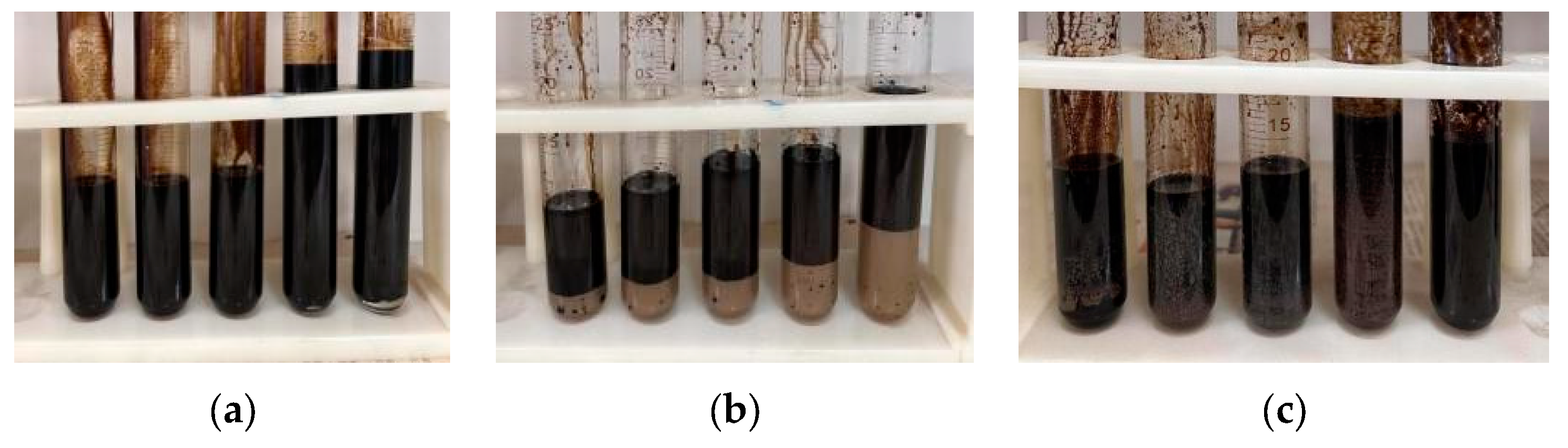
2.2. Emulsification and Viscosity Reduction Experiment

In order to determine the emulsification viscosity reduction effect, the viscosity reducers were mixed with heavy oil at the ratios of 2:1, 1:1, 1:2, 1:3, and 1:4 for 5 min. The viscosity was measured to analyze the viscosity reduction ability of the viscosity reducer, and the mixing effect and fluidity were observed. Then, these were placed at 25 °C for 144 h to observe the emulsification effect and analyze the emulsification ability of the viscosity reducer.

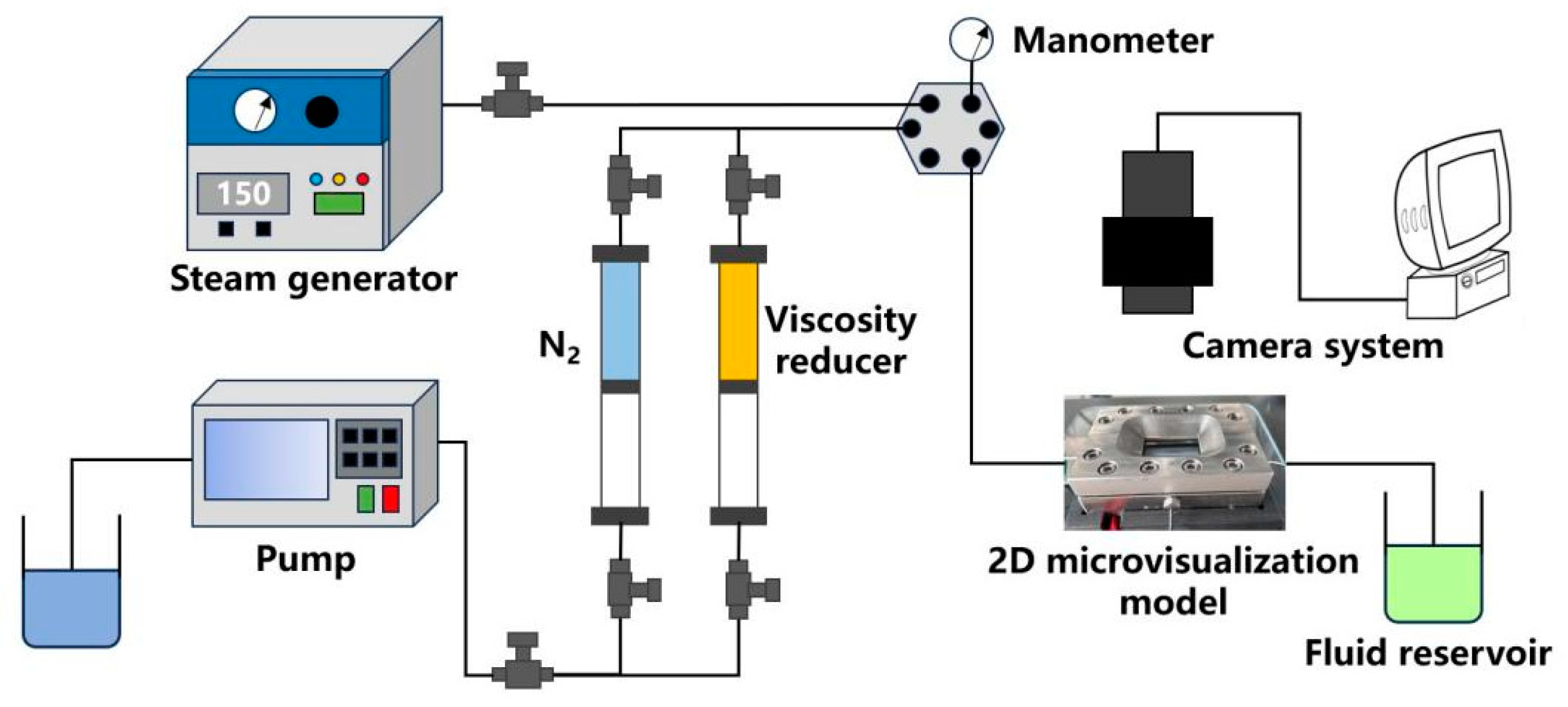
2.3. Two-Dimensional Microscopic Seepage Experiment

The two-dimensional microscopic seepage experiment system consisted of a microscopic model, steam generator, constant velocity and pressure pump, N2 cylinder, pressure gauge, and camera system. The pore structure of the two-dimensional microscopic model was the same as the cross-sectional CT image of a natural core, with an injection hole and an output hole to allow fluid to pass through the pore space. The side length of the model was 43 mm, the pore diameter was 30–40 μm, the porosity was 35%, and the permeability was 2 μm2.
First, the heavy oil was saturated and aged for 48 h in the two-dimensional microscopic model to simulate the distribution and physical properties of heavy oil in reservoir pores. The model confining pressure was 6 MPa, and the experimental temperature was 30 °C, which was consistent with the field reservoir parameters. The devices were sequentially connected as shown in Figure 1, and the two-dimensional microscopic model was placed within the field of view of the camera system. Three cycles of oil displacement were carried out for each viscosity reducer system with steam flooding, viscosity reducer flooding, and N2 flooding successively in each cycle. High-temperature steam was injected at 150 °C for 30 min. The injection speed and injection amount for viscosity reducer flooding were 50 μL/min and 500 μL, respectively. The injection speed and injection amount for N2 flooding were 100 μL/min and 2000 μL, respectively.
The two-dimensional microscopic model flow field was divided into two observation regions [Figure 2]: the primary stream region and the margin region. During the experiment, dynamic seepage law, microscopic occurrence state, and steam chamber development were observed. The overall recovery was composed of two components: one was displacement efficiency and the other was sweeping efficiency. Displacement efficiency was reflected in the remaining oil distribution in the primary stream region, and sweeping efficiency was reflected in the remaining oil distribution in the margin region. Overall images were taken at each node for binarization processing, and the overall remaining oil saturation, the primary stream region, and the margin region were calculated, which, respectively, corresponded to changes in overall oil recovery, displacement efficiency, and sweeping efficiency [15].

3. Results

3.1. The Mechanical Characteristics of the Interface between Multiphase Fluid and Heavy Oil

Based on the experimental results of emulsification viscosity reduction, the interface mechanical characteristics of oil–multiphase fluid in different viscosity reducer systems were obtained.
Viscosity reducer A dissolved heavy oil, the dissolved amount was positively correlated with viscosity reduction content, and the maximum dissolved amount was 55%. The fluidity of the dissolved part was good. No stratification occurred [Figure 3a]. Viscosity reducer B took the shortest time to completely dissolve the heavy oil and the fluidity of the dissolved part was good. At 30 min, the mixed solution gradually stratified; the higher the viscosity reducer content, the faster the stratification, and the longer the process [Figure 3b]. Viscosity reducer C dissolved heavy oil quickly. No stratification occurred. It was easy to produce brown precipitates attached to the wall of the test tube [Figure 3c].
The viscosity reduction effects of A and C were more obviously affected by the concentration. The viscosities of A and C were 20 mPa·s and 4 mPa·s, respectively, when the ratio of the viscosity reducer to heavy oil was 2:1 [Figure 4a,c]. The viscosity reduction effect of B varied linearly with the concentration of the viscosity reducer. When the ratio of the viscosity reducer to heavy oil was 2:1, the viscosity was 70 mPa·s [Figure 4b].

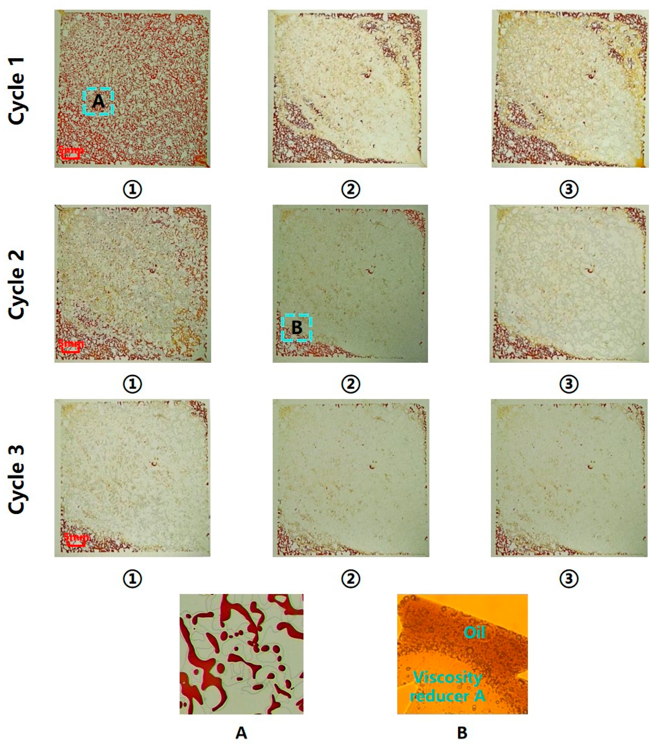
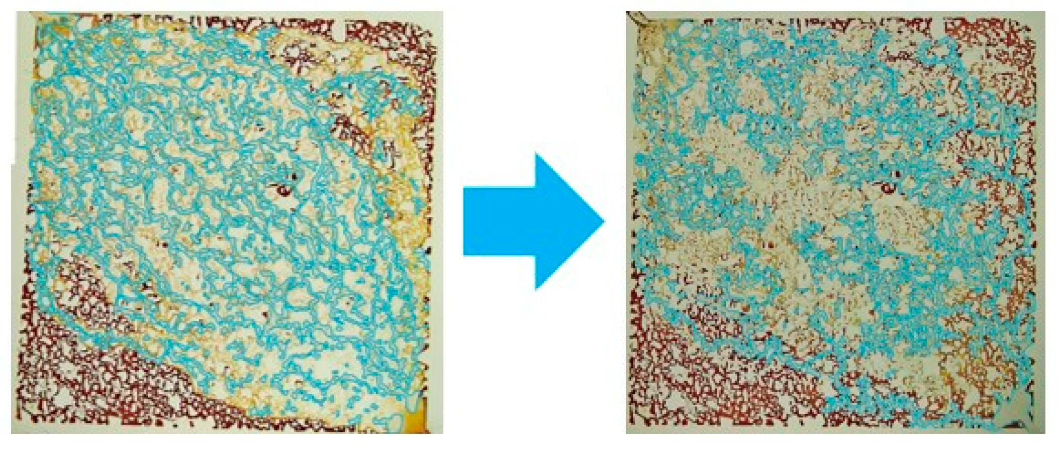
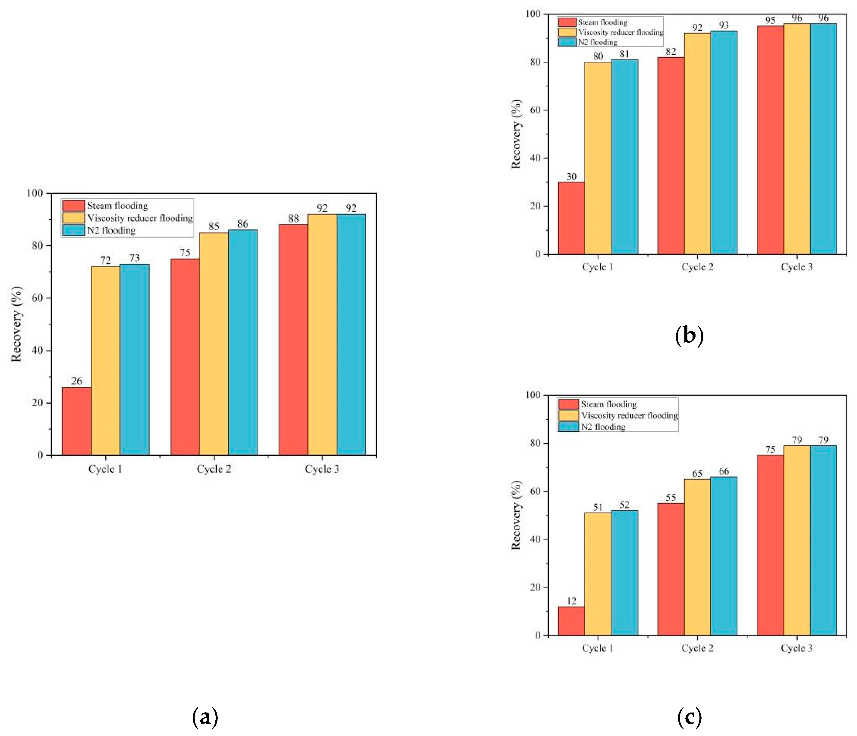
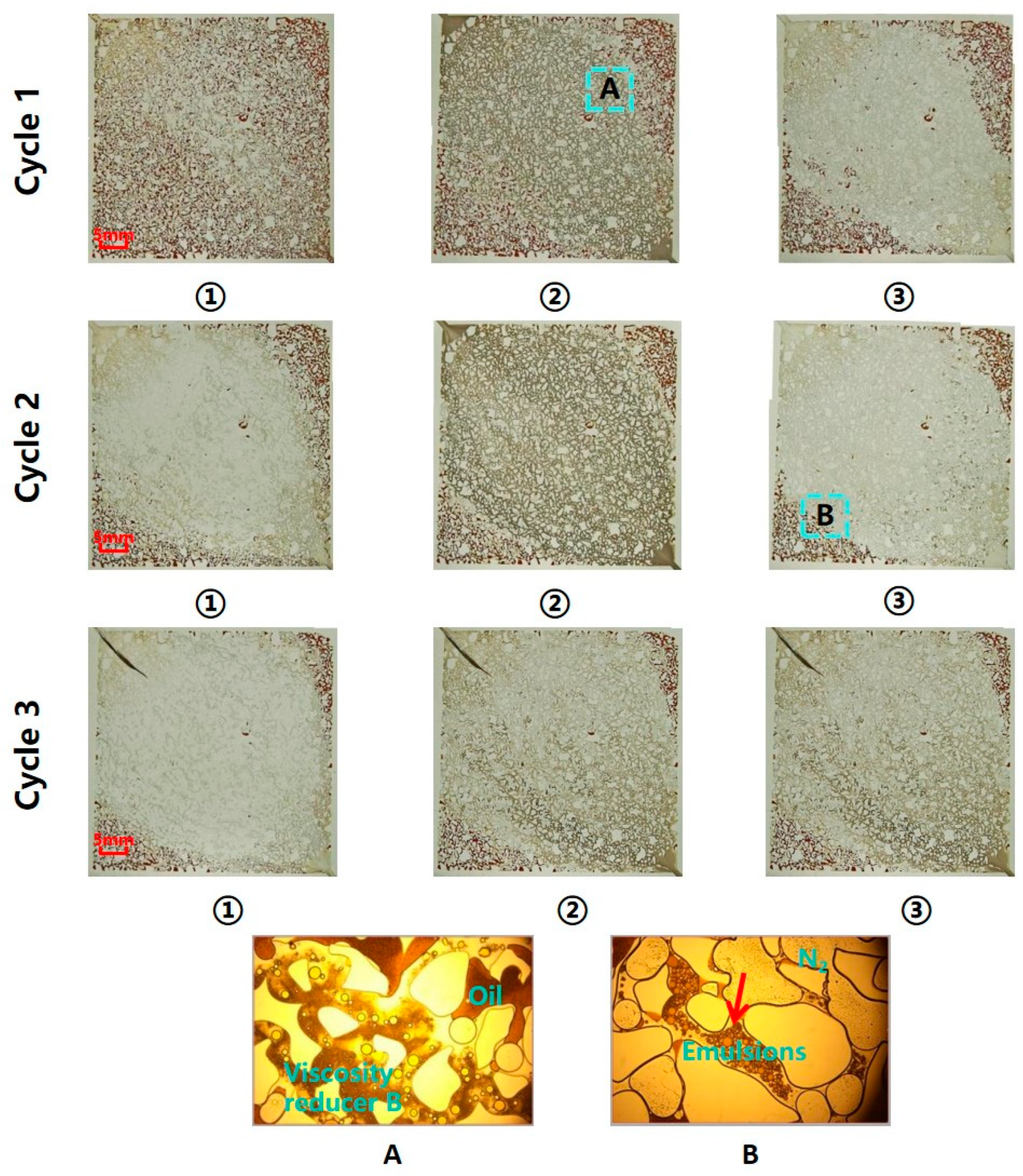
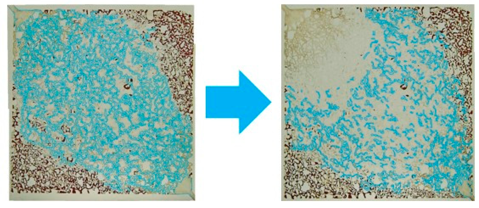
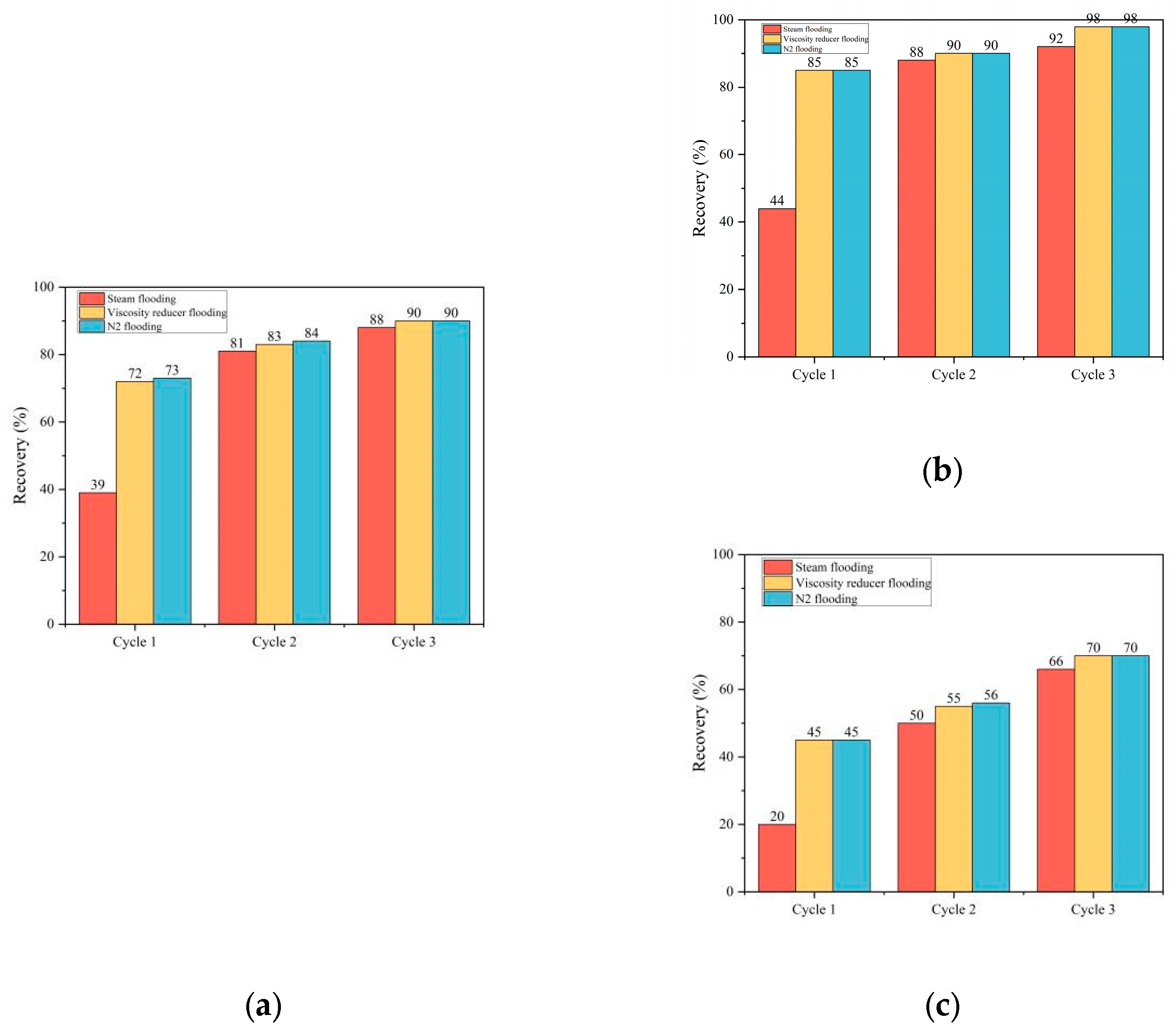
3.2. Two-Dimensional Microscopic Multiphase Seepage Characteristics

Three cyclic combined flooding experiments were carried out for each viscosity reducer system. The dynamic seepage law and microscopic occurrence state were observed.
In the viscosity reducer A system [Figure 5], the recovery of steam flooding in the first cycle was only 26%, forming the initial flow channel. The viscosity reducer flooding dissolved the oil in the primary stream region to improve the displacement efficiency, while the oil dissolved in the margin region to expand the sweep area, and the recovery reached 72%. N2 flooding drove away part of the remaining oil to improve the displacement efficiency, and N2 was continuously distributed in most of the flow area. After steam flooding in the second cycle, the recovery only increased by 2%, and N2 distributed continuously at the edge of the steam chamber. The remaining oil in the primary stream region reduced, and the remaining oil in the margin region was almost unchanged [Figure 6]. In the subsequent cycle, the viscosity reducer flooding effect was significant, and the steam flooding and N2 flooding effects gradually weakened. The final recovery was 92%.
According to the oil recovery results, the improvement of oil recovery in the viscosity reducer A flooding system depended on the viscosity reducer flooding, which contributed 60% [Figure 7a]. After the viscosity reducer flooding in the first cycle, the displacement efficiency increased by 50%, and the sweeping efficiency increased by 39%. Steam flooding and N2 flooding assisted in expanding the sweep area [Figure 7b,c].
In the viscosity reducer B system [Figure 8], the first steam flooding effect was the same as in the previous system. Viscosity reducer flooding emulsified heavy oil in the primary stream region, but the emulsification progress was slow in the margin region. The recovery reached 72%. After N2 flooding, continuous N2 occupied the flow area and pushed part of the emulsion away. After the second steam flooding, the N2 distribution decreased and the sweep area expanded. The remaining oil in the steam chamber reduced [Figure 9]. Subsequent viscosity reducer flooding continued to emulsify the oil, and steam flooding and N2 flooding continued to displace the emulsion to improve the displacement efficiency. The final recovery reached 90%.
According to the oil recovery results, the recovery improvement was supported by the first viscosity reducer flooding and subsequent steam flooding, which increased the recovery by 33% and 12%, respectively [Figure 10a]. The displacement efficiency was mainly improved by viscosity reducer flooding, which increased the displacement efficiency by 49%. The sweep area was expanded by the viscosity reducer flooding in the first cycle [Figure 10b,c].
In the viscosity reducer C system [Figure 11], the displacement effect in the primary stream region and the sweeping effect in the margin region of the viscosity reducer were poor, and the recovery reached 45%. The effect of N2 flooding was not obvious. The second steam flooding expanded the sweep area, N2 distribution significantly reduced, and the recovery increased to 62% [Figure 12]. The viscosity reducer dissolved the oil in the primary stream region and emulsified the oil in the margin region. However, viscous precipitation was produced to block the pores and affected the seepage. In the third cycle, steam flooding removed part of the remaining oil and viscous precipitates. The final recovery reached 85%.
According to the oil recovery results, the recovery improvement was dependent on the first viscosity reducer and subsequent steam flooding, which increased recovery by 15% and 23%, respectively [Figure 13a]. The displacement efficiency depended on the first viscosity reducer flooding and the subsequent steam flooding. The sweeping efficiency depended on steam flooding, and the cumulative expanded sweep area reached 57% [Figure 13b,c].

4. Discussion

4.1. Oil Displacement Mechanism of Each Slug in HDNS Combined Flooding

In this study, it was found that the mechanisms of steam flooding, viscosity reducer flooding, and N2 flooding in HDNS combined flooding were different. The viscosity reducer flooding had the most significant effect on enhanced oil recovery.
The recovery of combined flooding in the three systems was 92%, 90%, and 85%, respectively. The viscosity reduction efficiency of steam flooding was low, and the maximum recovery in the first cycle was only 40%. The oil displacement effect was the same as that of pure steam flooding heating viscosity reduction, and the sweep area showed difficulty expanding after steam channeling [16,17,18]. The viscosity reduction efficiency of viscosity reducer flooding was in the order of A > B > C, and the reducers’ contributions to oil recovery were 65%, 41%, and 30%. This shows that, similar to related studies, viscosity reducer flooding played a major role in viscosity reduction and significantly affected the final recovery [19,20,21]. The maximum contribution of N2 flooding to the recovery was only 6%. Related studies suggested that N2 increased displacement efficiency [22,23]. This study showed that the effect of N2 displacement emulsion was more obvious at the pore scale.

4.2. The Interaction of Each Slug in HDNS Combined Flooding

All slugs interacted with each other in HDNS combined flooding. In particular, the interactions of the viscosity reducer with steam and of N2 with steam were crucial for enhanced oil recovery.
The viscosity reducer interacted with the steam slug. Relevant studies suggest that the sweep areas of pure viscosity reducer flooding or pure steam flooding were small, but after the combination of the two, the steam transported the viscosity reducer to expand the sweep area [24,25,26]. However, in this study, when the viscosity reduction efficiency of the viscosity reducer was high, the sweep area was expanded by the viscosity reducer flooding. For example, in the viscosity reducer A system, the viscosity reducer contributed to 58% of the sweeping efficiency. When the viscosity reduction efficiency of the viscosity reducer was low, it was more dependent on steam flooding to expand the sweep area. For example, in the viscosity reducer C system, steam contributed to 57% of the sweeping efficiency.
The N2 interacted with the steam slug. In a macroscopic experiment, the development of the steam chamber was inferred from the temperature field, and N2 was believed to maintain the temperature of the steam chamber longitudinally and drive the steam to expand laterally [27,28]. In this study, transverse N2 distribution was observed at the pore scale, and it showed that N2 was conducive to expanding the sweep area of the subsequent steam and viscosity reducer [Figure 12]. However, the gain effect of N2 thermal insulation characteristics was related to the transverse remaining oil distribution. When there was more remaining oil in the steam chamber, the subsequent steam flooding in the viscosity reducer C system increased the displacement efficiency by 25%. When there was less remaining oil in the steam chamber, the thermal insulation characteristics of the peripheral N2 had little effect on enhanced oil recovery. On the contrary, it prevented the steam from transferring heat to the remaining oil in the margin region and reduced the recovery [Figure 6 and Figure 9].

4.3. Pore-Scale Viscosity Reduction Mechanism of Different Viscosity Reducers

In this study, the three viscosity reducers showed the viscosity reduction mechanisms of dissolution, emulsification, and the coexistence of dissolution and emulsification.
The displacement efficiency and sweeping efficiency of the oil-soluble viscosity reducer based on dissolution were higher. The oil-soluble viscosity reducer destroyed the aggregates of asphaltene and colloid molecules in heavy oil to improve the fluidity [29,30]. However, some studies suggested that the preparation of oil-soluble viscosity reducers was complicated and the on-site consumption was large, which may lead to higher production costs [31,32,33].
The water-soluble viscosity reducer based on emulsification had higher displacement efficiency and average sweeping efficiency. The water-soluble viscosity reducer emulsified oil to form O/W emulsions to enhance fluidity, while large-sized emulsions blocked hypertonic channels to expand the sweep area [31,34,35]. In this study, it was shown that a strong emulsification ability was conducive to stripping oil film, but the resulting emulsion with a small particle size had difficulty plugging pores, and was more suitable for low-permeability reservoirs.
The displacement efficiency and sweeping efficiency of the composite viscosity reducer with both a dissolution and emulsification mechanism were lower. The limiting factor was precipitation, which was 80% asphaltene and 20% gum. Relevant studies show that precipitation is caused by a complex reaction, and this phenomenon of reservoir damage exists in many viscosity reducer systems [36,37,38,39]. Therefore, it is necessary to avoid the precipitation of heavy components in production, which seriously affects seepage characteristics.

5. Conclusions

As a kind of enhanced oil recovery technology, HDNS combined flooding showed an additive production enhancement effect due to the interaction of slugs. As the process with the most significant effect on recovery, viscosity reducer flooding showed different viscosity reduction mechanisms, resulting in the ability to improve viscosity-reducing efficiency in the order of A > B > C.
In the system where a high viscosity reduction efficiency was shown by the viscosity reducer, the enhancements of both sweeping efficiency and oil displacement efficiency were primarily influenced by the viscosity reducer flooding, and contributed to 65% of the final recovery. Steam flooding was more inclined to assist in improving displacement efficiency, and the contribution to recovery was only 30%. N2 flooding improved the displacement efficiency. However, due to the small amount of remaining oil in the steam chamber, the gain effect of its thermal insulation characteristics was limited, and it may have prevented the transfer of heat to the remaining oil in the margin region and affect recovery. In the system where a low viscosity reduction efficiency was shown by the viscosity reducer, steam flooding significantly improved the sweeping efficiency and displacement efficiency by 61% and 57%, respectively. N2 was helpful for expanding the sweep area of the subsequent steam and viscosity reducer, and maintained the temperature of the steam chamber to improve the displacement efficiency.
In summary, in actual heavy oil production, it is necessary to optimize the process of HDNS combined flooding and screen the viscosity reducer according to the actual conditions of the reservoir and the characteristics of different viscosity reducers.

Author Contributions

Z.S. contributed to project administration and writing—review, and editing. B.Z. contributed to writing—original draft and experimental work. Y.Z. contributed to data statistics and analysis. All authors have read and agreed to the published version of the manuscript.

Funding

This research was funded by National Natural Science Foundation of China (Project No. 42102163).

Data Availability Statement

The data that support the findings of this study are available from the corresponding author upon reasonable request.

Conflicts of Interest

The authors have no conflicts to disclose.

References

  1. Wang, X.; Wang, J.; Qiao, M. Horizontal well, nitrogen and viscosity reducer assisted steam huff and puff technology Taking super heavy oil in shallow and thin beds, Chunfeng Oilfield, Junggar Basin, NW China, as an example. Pet. Explor. Dev. 2013, 40, 104–110. [Google Scholar] [CrossRef]
  2. Sun, R.; Sun, Y.; Fan, K.; Yang, S.; Qiao, M.; Wang, X.; Yang, Y. Experiment Studies on Horizontal well—N2—Viscosity Depressant—Steam Stimulation for Shallow Thin Super-Heavy Oil Reservoirs. In Proceedings of the SPE Trinidad and Tobago Section Energy Resources Conference, Port of Spain, Trinidad and Tobago, 25–26 June 2018. SPE-191252-MS. [Google Scholar]
  3. Shi, W.; Ma, Y.; Tao, L.; Zhang, N.; Ma, C.; Bai, J.; Xu, Z.; Zhu, Q.; Zhong, Y. Study of the enhanced oil recovery mechanism and remaining oil state of heavy oil after viscosity-reducer-assisted CO2 foam flooding: 2D microvisualization experimental case. Energy Fuels 2023, 37, 18620–18631. [Google Scholar] [CrossRef]
  4. Du, Q.; Liu, H.; Wu, G.; Hou, J.; Zhou, K.; Liu, Y. Application of flue-gas foam in thermal-chemical flooding for medium-depth heavy oil reservoirs. Energy Sci. Eng. 2019, 7, 2936–2949. [Google Scholar] [CrossRef]
  5. Liu, Y.; Zhang, C.; Li, S.; Li, Z. Study of steam heat transfer enhanced by CO2 and chemical agents: In heavy oil production. Pet. Sci. 2023, 20, 1030–1043. [Google Scholar] [CrossRef]
  6. Pu, W.; Gao, H.; Li, Y.; Luo, Q. Performance and mechanisms of enhanced oil recovery via CO2 assisted steam flooding technique in high heterogeneity heavy oil reservoir: PVT and 3D experimental studies. Pet. Sci. Technol. 2020, 38, 823–835. [Google Scholar] [CrossRef]
  7. Li, S.; Peng, D.; Feng, S.; Wang, Z.; Zhang, K. Dimethyl ether-steam assisted gravity drainage: Physical 2D heavy oil simulation. Fuel 2023, 342, 127821. [Google Scholar] [CrossRef]
  8. Huang, S.; Chen, X.; Liu, H.; Xia, Y.; Jiang, J.; Cao, M.; Li, A.; Yang, M. Experimental and numerical study of steam-chamber evolution during solvent-enhanced steam flooding in thin heavy-oil reservoirs. J. Pet. Sci. Eng. 2019, 172, 776–786. [Google Scholar] [CrossRef]
  9. Huang, Y.; Xiao, W.; Chen, S.; Li, B.; Du, L.; Li, B. A Study on the Adaptability of Nonhydrocarbon Gas-Assisted Steam Flooding to the Development of Heavy Oil Reservoirs. Energies 2022, 15, 4805. [Google Scholar] [CrossRef]
  10. Du, L.; Li, B.; Ji, Y.; Gai, P.; Lu, T.; Li, B.; Wang, J. A novel strategy to improve steam heat utilization and reduce carbon emissions during heavy oil development. Energy 2023, 266, 126328. [Google Scholar] [CrossRef]
  11. Pang, Z.; Hong, Q.; Liu, D.; Wang, B. The macro and micro analysis on EOR mechanisms during steam and solvent thermal recovery in heavy oil reservoirs. Geoenergy Sci. Eng. 2023, 230, 212244. [Google Scholar] [CrossRef]
  12. Wang, Y.; Liu, H.; Zhang, Q.; Chen, Z.; Wang, J.; Dong, X.; Chen, F. Pore-scale experimental study on EOR mechanisms of combining thermal and chemical flooding in heavy oil reservoirs. J. Pet. Sci. Eng. 2020, 185, 106649. [Google Scholar] [CrossRef]
  13. Mohammadzadeh, O.; Rezaei, N.; Chatzis, I. Pore-Level investigation of heavy oil and bitumen recovery using solvent—Aided steam assisted gravity drainage (SA-SAGD) process. Energy Fuels 2010, 24, 6327–6345. [Google Scholar] [CrossRef]
  14. Lyu, X. Visualized study of thermochemistry assisted steam flooding to improve oil recovery in heavy oil reservoir with glass micromodels. Fuel 2018, 218, 118–126. [Google Scholar] [CrossRef]
  15. Yu, X.; Ma, T.; Li, G.; Wang, W.; Song, Z. Pore-scale flooding experiments reveal the thermally regulated flow fields of the curdlan solution. Phys. Fluids 2024, 36, 062010. [Google Scholar] [CrossRef]
  16. Yang, X.; Zhao, H.; Zhang, B.; Zhao, Q.; Cheng, Y.; Zhang, Y.; Li, Y. Displacement characteristics and produced oil properties in steam flood heavy oil process. Energies 2022, 15, 6246. [Google Scholar] [CrossRef]
  17. Wu, Z.; Wang, L.; Xie, C.; Yang, W. Experimental investigation on improved heavy oil recovery by air assisted steam injection with 2D visualized models. Fuel 2019, 252, 109–115. [Google Scholar] [CrossRef]
  18. Pei, H.; Zheng, J.; Zhang, G.; Zhang, J.; Zhao, J. Combination of nano-bentonite stabilized foam and ultra-low IFT surfactant additives assisted steam injection to enhanced heavy oil recovery. J. Mol. Liq. 2022, 368, 120647. [Google Scholar] [CrossRef]
  19. Borisov, D.N.; Tazeev, D.I.; Milordov, D.V.; Mironov, N.A.; Borisova, Y.Y.; Yakubov, M.R.; Beregovoy, A.N.; Amerkhanov, M.I.; Khisamov, R.S. Physical modeling of the composite solvent injection to improve the ultra-viscous oil recovery efficiency steam-assisted gravity drainage. J. Pet. Sci. Eng. 2018, 169, 337–343. [Google Scholar] [CrossRef]
  20. Liu, W.; Du, L.; Zou, X.; Liu, T.; Wu, X.; Wang, Y.; Dong, J. Experimental study on the enhanced ultra-heavy oil recovery using an oil-soluble viscosity reducer and CO2 assisted steam flooding. Geoenergy Sci. Eng. 2023, 222, 211409. [Google Scholar] [CrossRef]
  21. Kar, T.; Hascakir, B. Effect of solvent type on emulsion formation in steam and solvent-steam flooding processes for heavy oil recovery. Colloids Surf. A Physicochem. Eng. Asp. 2021, 611, 125783. [Google Scholar] [CrossRef]
  22. Fan, J.; Shi, J.; Yang, J.; Jin, B. Experimental study on the mechanism of enhanced oil recovery by air assisted cyclic steam stimulation process in extra-heavy oil reservoirs. Energy Sources Part A Recovery Util. Environ. Eff. 2019, 44, 4902–4916. [Google Scholar] [CrossRef]
  23. Qin, J.; Zhang, J.; Zhu, S.; Wang, Y.; Wan, T. Multi-Component thermal fluid injection performance in recovery of heavy oil reservoirs. Front. Energy Res. 2021, 9, 803540. [Google Scholar] [CrossRef]
  24. Li, Y.; Liu, H.; Wang, W.; Loh, W.L.; Lyu, X.; Li, X.; Peng, C.; Peng, H. Microvisual investigation on steam-assisted heavy oil extraction behavior in heterogeneous porous media. Energy Fuels 2023, 37, 11776–11786. [Google Scholar] [CrossRef]
  25. Wu, B.; Gao, J. A viscosity reduction study on chinese extra heavy oil by the addition of synthesized novel oil-soluble viscosity-reducing agents. Pet. Sci. Technol. 2010, 28, 1919–1935. [Google Scholar] [CrossRef]
  26. Li, S.; Han, R.; Wang, Q.; Wei, X. Visual Flooding Experiment of Hot Water, Steam and Solvent under SAGD. In Proceedings of the ASME 2021 40th International Conference on Ocean, Offshore and Arctic Engineering, New York, NY, USA, 21–30 June 2021. [Google Scholar]
  27. Wang, Z.; Du, H.; Li, S.; Li, S. Experimental study on gas-assisted cyclic steam stimulation under heavy-oil sandstone reservoir conditions: Effect of N2/CO2 ratio and foaming agent. Geoenergy Sci. Eng. 2023, 228, 211976. [Google Scholar] [CrossRef]
  28. Tao, L.; Yuan, X.; Huang, S.; Liu, N.; Zhang, N.; Li, B. 3D experimental investigation on enhanced oil recovery by flue gas assisted steam assisted gravity drainage. Energy Explor. Exploit. 2021, 39, 1162–1183. [Google Scholar] [CrossRef]
  29. Zhang, N.; Liu, W.; Zou, X.; Wang, S.; Sun, Q.; Li, B.; Li, S.; Bhusal, A.; Wang, S.; Li, Z. Experimental study on thermochemical composite system huff-n-puff process in ultra-heavy oil production. Fuel 2023, 332, 126014. [Google Scholar] [CrossRef]
  30. Li, Z.; Bai, S. Insights into enhanced oil recovery by coupling branched-preformed particle gel and viscosity reducer flooding in ordinary heavy oil reservoir. Geofluids 2023, 2023, 9357711. [Google Scholar] [CrossRef]
  31. Zhai, M.; Du, Q.; Liu, Y.; Wu, G.; Sun, J.; Sha, Y.; Hou, J. Potential of a new water-soluble agent for enhancing heavy oil recovery: A pore-scale investigation. J. Pet. Sci. Eng. 2022, 208, 109646. [Google Scholar] [CrossRef]
  32. Guo, J.; Wang, H.; Chen, C.; Chen, Y.; Xie, X. Synthesis and evaluation of an oil-soluble viscosity reducer for heavy oil. Pet. Sci. 2010, 7, 536–540. [Google Scholar] [CrossRef]
  33. Mao, J.; Liu, J.; Peng, Y.; Zhang, Z.; Zhao, J. Quadripolymers as viscosity reducers for heavy oil. Energy Fuels 2017, 32, 119–124. [Google Scholar] [CrossRef]
  34. Zhang, Z.; Wang, Y.; Ding, M.; Mao, D.; Chen, M.; Han, Y.; Liu, Y.; Xue, X. Effects of viscosification, ultra-low interfacial tension, and emulsification on heavy oil recovery by combination flooding. J. Mol. Liq. 2023, 380, 121698. [Google Scholar] [CrossRef]
  35. Wu, Z.; Liu, H.; Wang, X. Adaptability research of thermal–chemical assisted steam injection in heavy oil reservoirs. J. Energy Resour. Technol. 2018, 140, 052901. [Google Scholar]
  36. Razavifar, M.; Qajar, J.; Riazi, M. Experimental study on pore-scale mechanisms of ultrasonic-assisted heavy oil recovery with solvent effects. J. Pet. Sci. Eng. 2022, 214, 110503. [Google Scholar] [CrossRef]
  37. Qi, Z.; Abedini, A.; Lele, P.; Mosavat, N.; Guerrero, A.; Sinton, D. Pore-scale analysis of condensing solvent bitumen extraction. Fuel 2017, 193, 284–293. [Google Scholar] [CrossRef]
  38. Xu, L.; Abedini, A.; Qi, Z.; Kim, M.; Guerrero, A.; Sinton, D. Pore-scale analysis of steam-solvent coinjection: Azeotropic temperature, dilution and asphaltene deposition. Fuel 2018, 220, 151–158. [Google Scholar] [CrossRef]
  39. Qi, Z.; Abedini, A.; Sharbatian, A.; Pang, Y.; Guerrero, A.; Sinton, D. Asphaltene deposition during bitumen extraction with natural gas condensate and naphtha. Energy Fuels 2018, 32, 1433–1439. [Google Scholar] [CrossRef]
Figure 1. Experimental equipment diagram.
Energies 17 04783 g001
Figure 2. Two-dimensional microscopic model.
Energies 17 04783 g002
Figure 3. The 144 h emulsification delamination effect (viscosity reducer-to-heavy oil ratios from left to right: 1:4, 1:3, 1:2, 1:1, 2:1). (a) Viscosity reducer A, (b) viscosity reducer B, and (c) viscosity reducer C.
Energies 17 04783 g003
Figure 4. Viscosity reduction effect of mixing viscosity reducers with heavy oil in proportion: (a) viscosity reducer A, (b) viscosity reducer B, and (c) viscosity reducer C.
Energies 17 04783 g004
Figure 5. Oil displacement effect and microscopic occurrence state at each stage in the viscosity reducer A system (image (A) is the form of the remaining oil after steam flooding, and image (B) is the process of the viscosity reducer dissolving oil).
Energies 17 04783 g005
Figure 6. N2 distribution in the viscosity reducer A system after N2 flooding in the first cycle to steam flooding in the second cycle (The blue lines outline the nitrogen distribution).
Energies 17 04783 g006
Figure 7. Viscosity reducer A system recovery: (a) overall, (b) primary stream region, and (c) margin region.
Energies 17 04783 g007
Figure 8. Oil displacement effect and microscopic occurrence state at each stage in the viscosity reducer B system (image (A) is the process of the viscosity reducer emulsifying oil, and image (B) is the process of N2 displacement emulsion).
Energies 17 04783 g008
Figure 9. N2 distribution in the viscosity reducer B system after N2 flooding in the first cycle to steam flooding in the second cycle (The blue lines outline the nitrogen distribution).
Energies 17 04783 g009
Figure 10. Viscosity reducer B system recovery: (a) overall, (b) primary stream region, and (c) margin region.
Energies 17 04783 g010
Figure 11. Oil displacement effect and microscopic occurrence state at each stage in the viscosity reducer C system (image (A) is the process of the viscosity reducer dissolving oil, image (B) is the process of the viscosity reducer emulsifying oil, and image (C) is the viscous precipitation).
Energies 17 04783 g011
Figure 12. N2 distribution in the viscosity reducer C system after N2 flooding in the first cycle to steam flooding in the second cycle (The blue lines outline the nitrogen distribution).
Energies 17 04783 g012
Figure 13. Viscosity reducer C system recovery: (a) overall, (b) primary stream region, and (c) margin region.
Energies 17 04783 g013
Disclaimer/Publisher’s Note: The statements, opinions and data contained in all publications are solely those of the individual author(s) and contributor(s) and not of MDPI and/or the editor(s). MDPI and/or the editor(s) disclaim responsibility for any injury to people or property resulting from any ideas, methods, instructions or products referred to in the content.

