
Assessment of Thermal Management Using a Phase-Change Material Heat Sink under Cyclic Thermal Loads


Abstract
:1. Introduction
2. Numerical Model
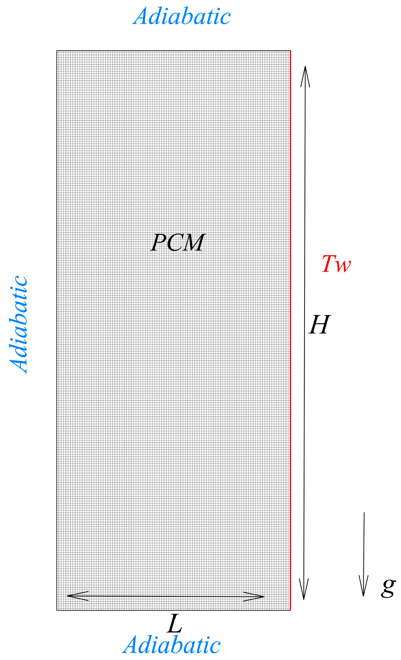
2.1. Physical Model
2.2. Governing Equations
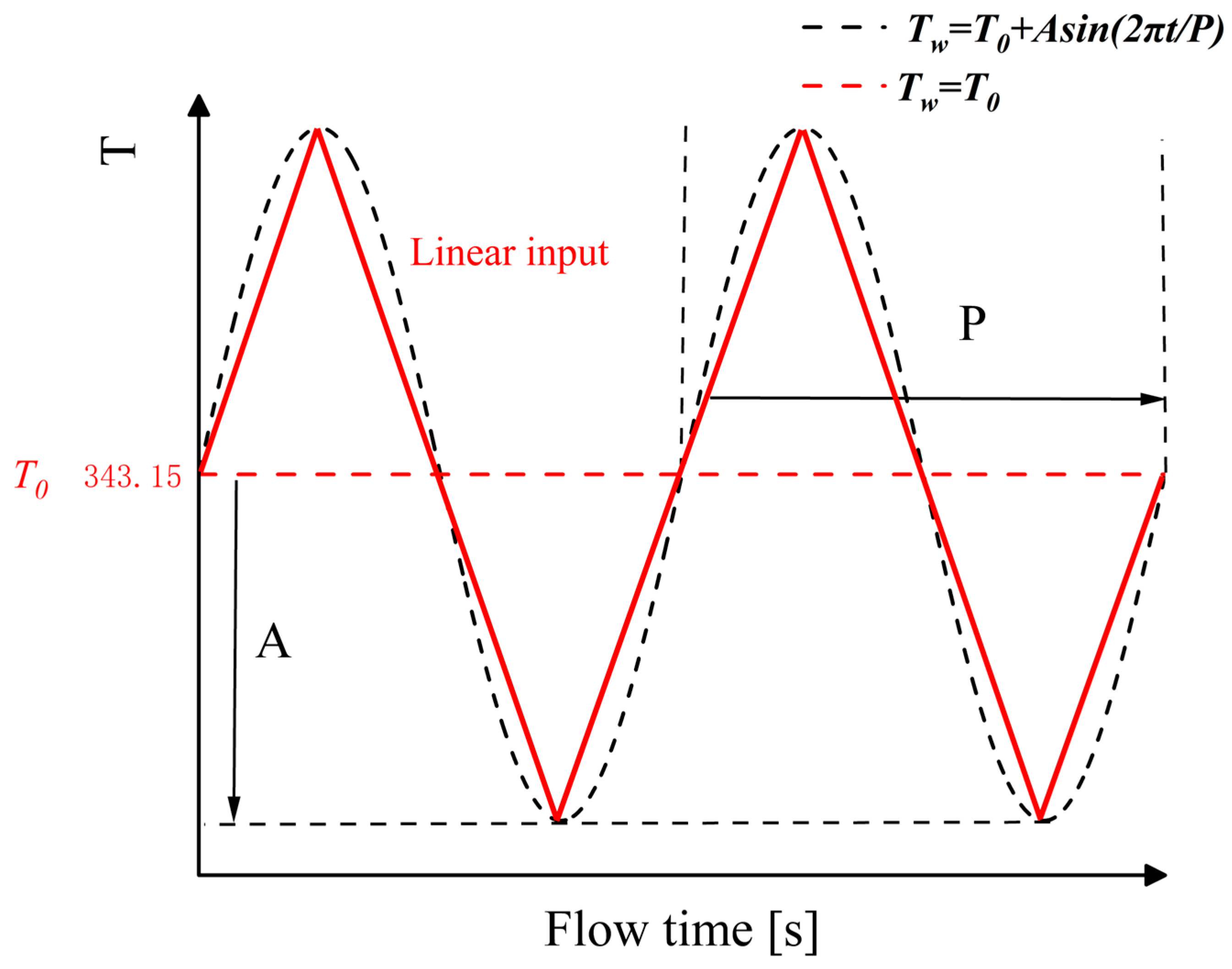
2.3. Boundary Conditions
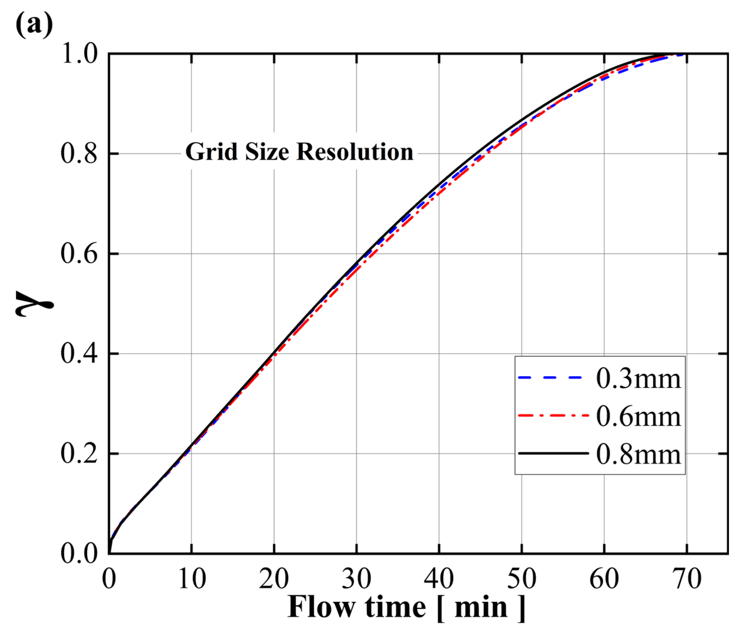
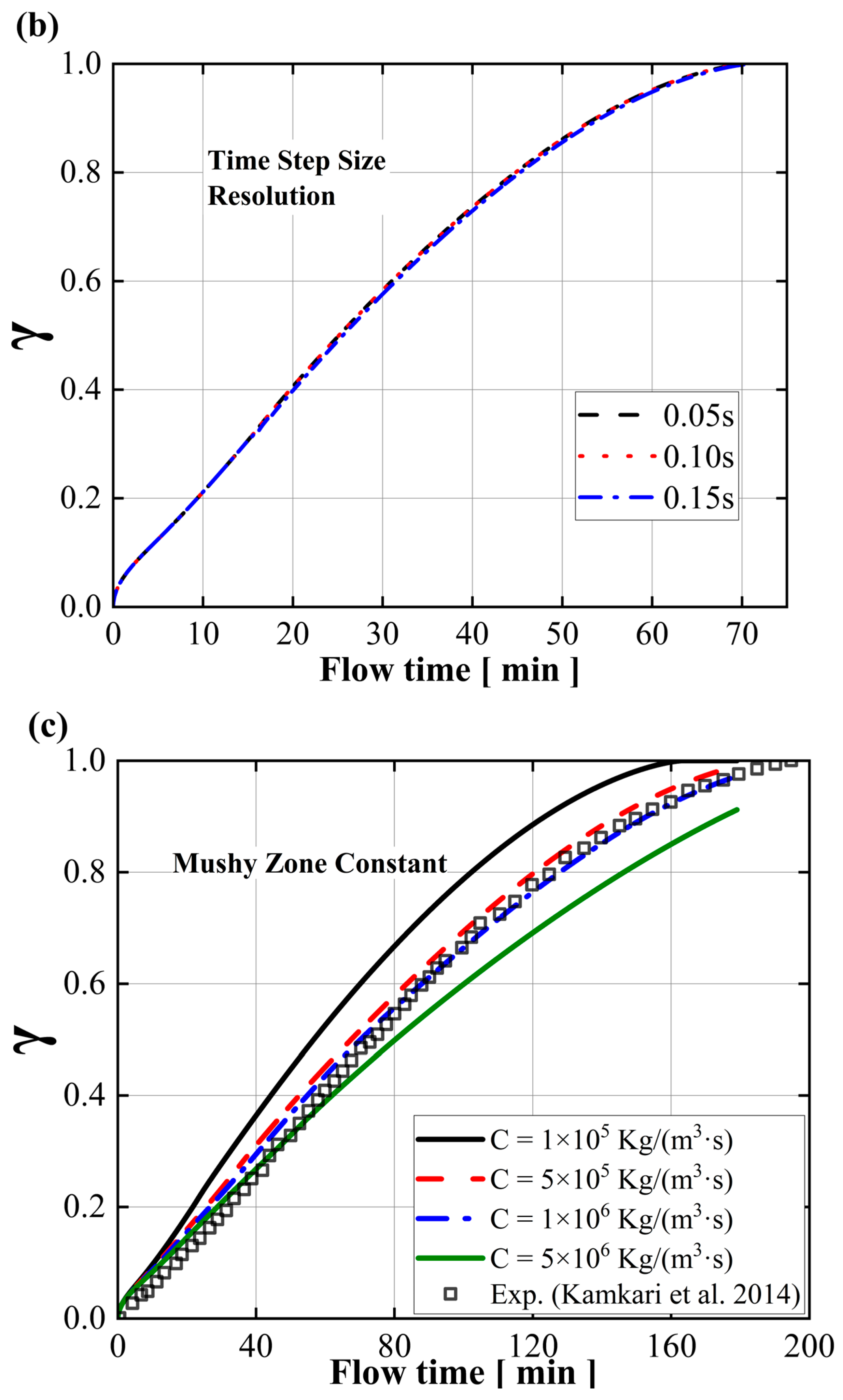
2.4. Numerical Strategies
3. Results and Discussion
3.1. Comparison of Heating Strategies
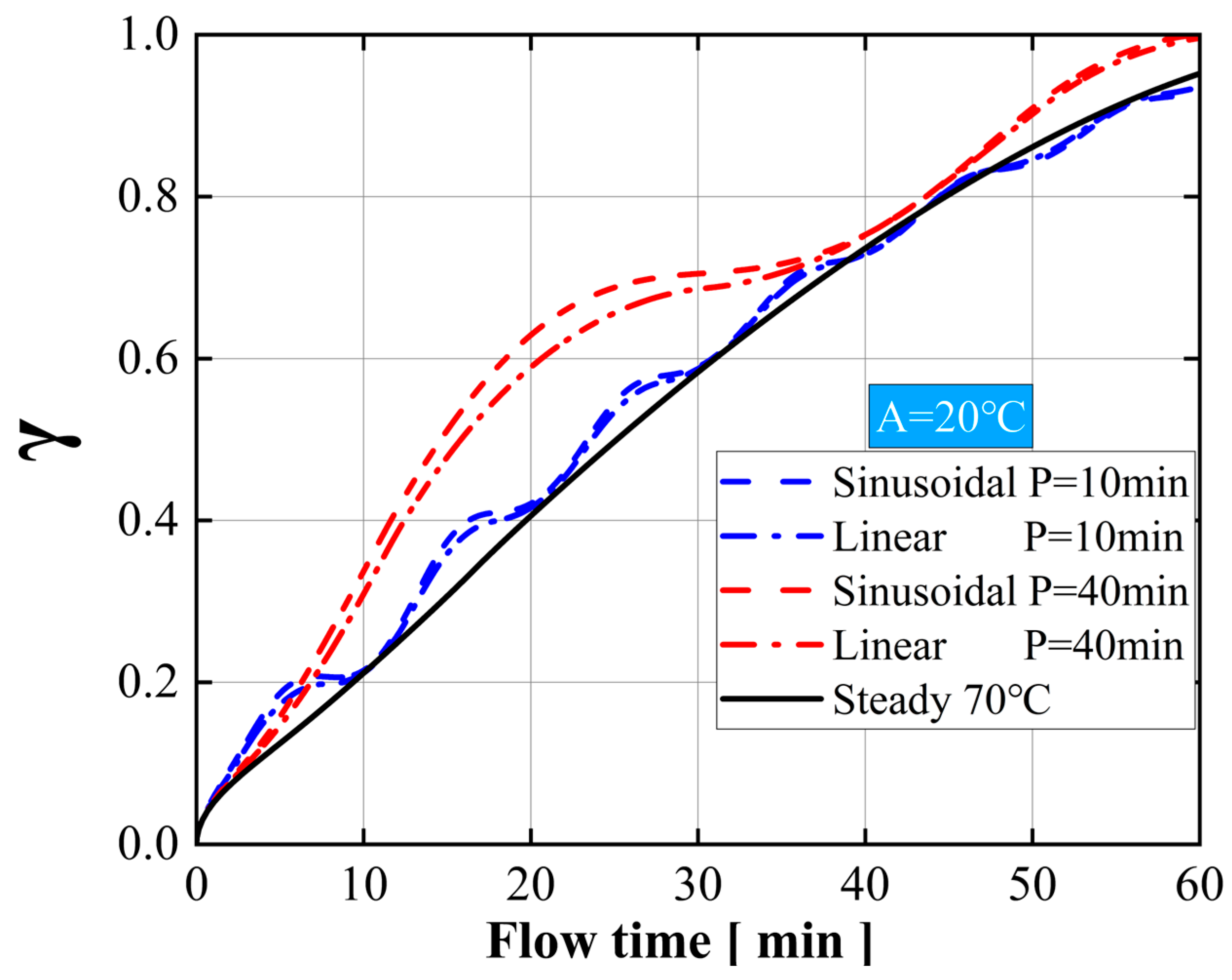
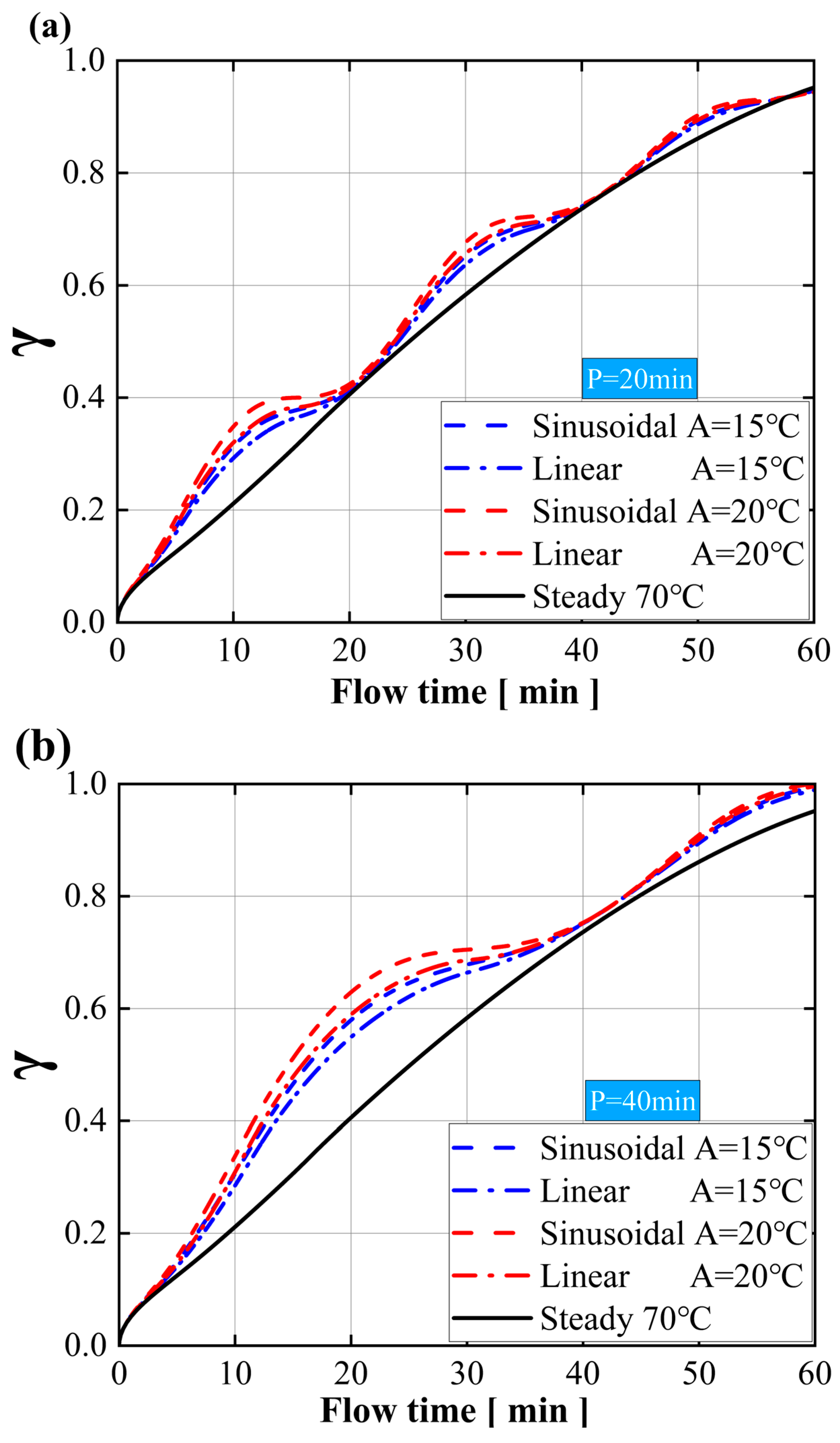
3.2. Effect of Sinusoidal Input Amplitude
3.3. Effect of Sinusoidal Input Period
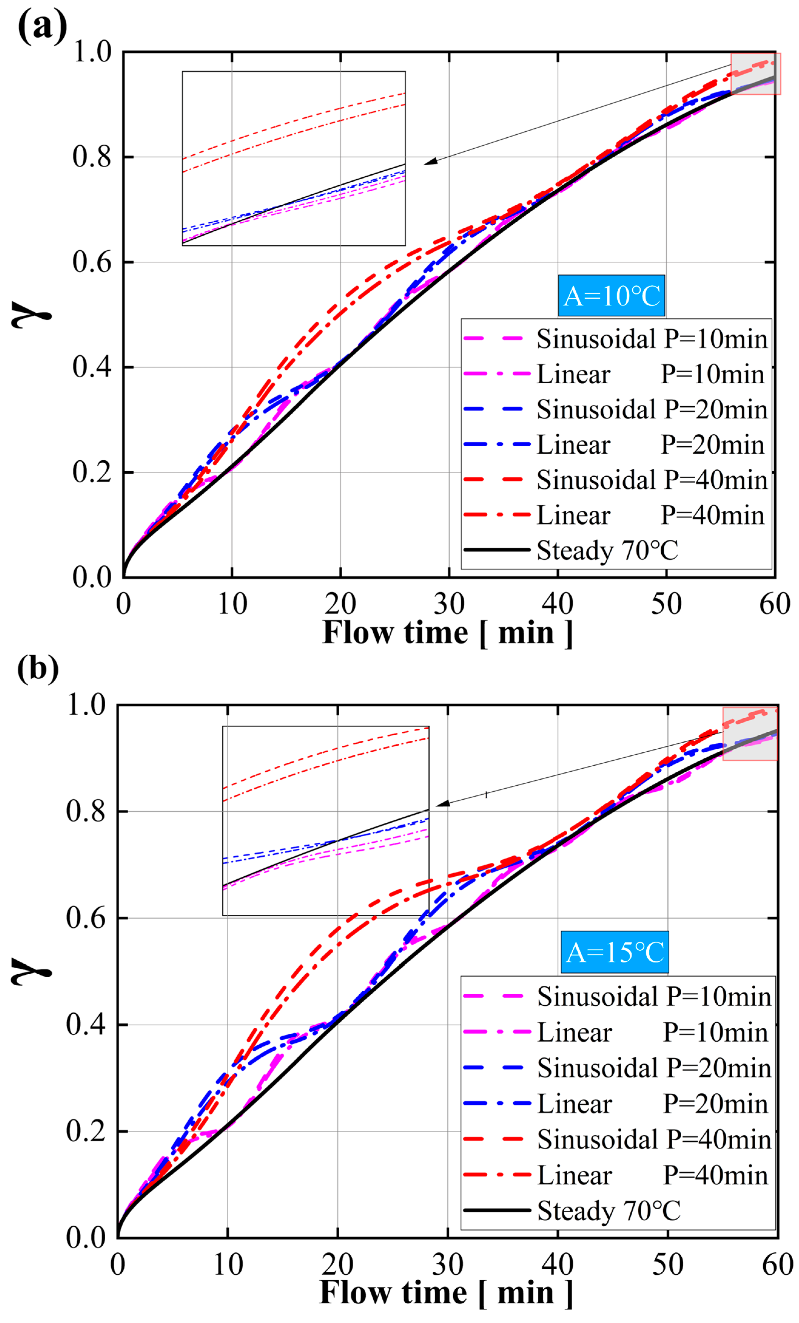
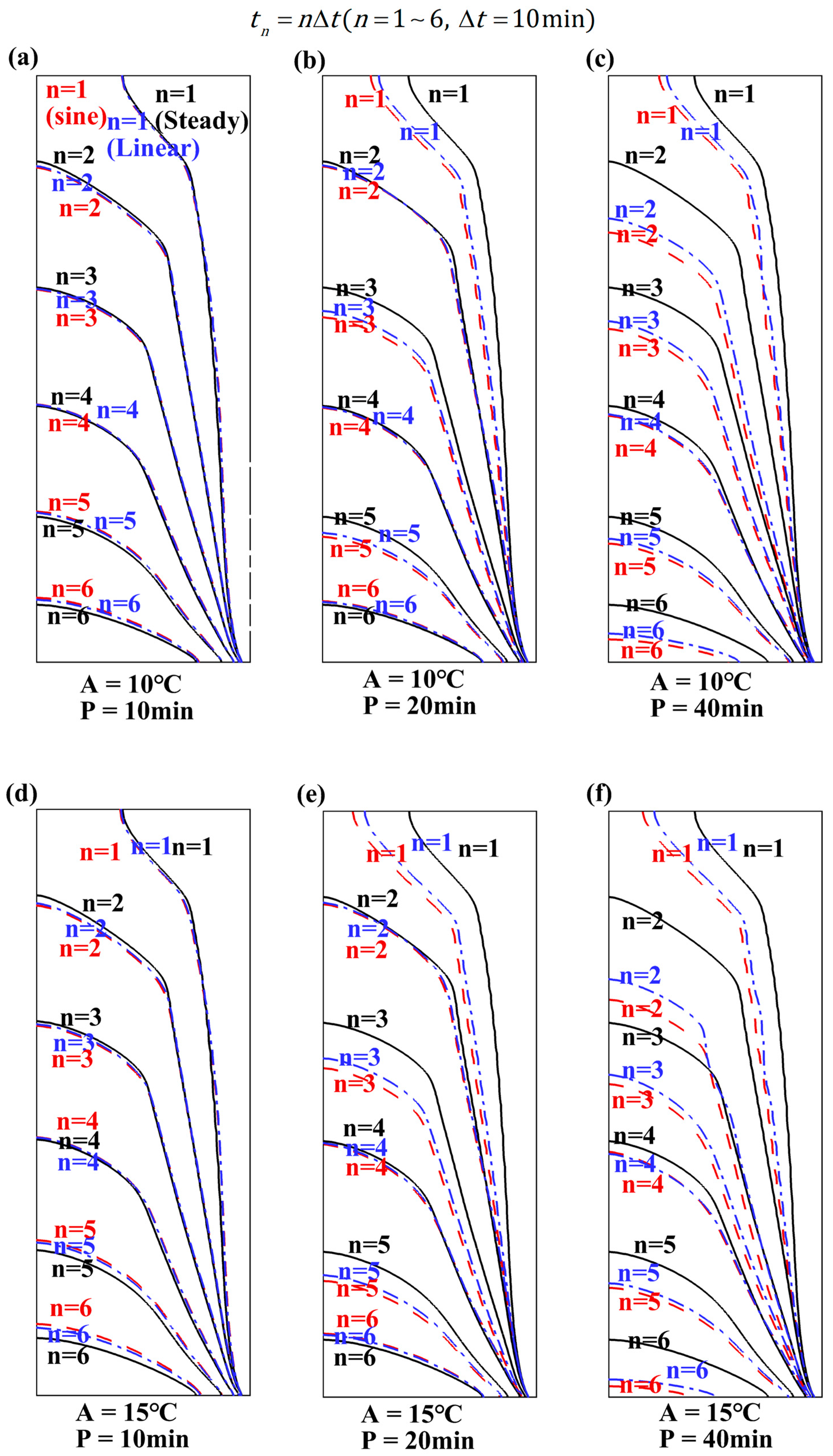
3.4. Comparison between Sine Input and Other Input Melting Rates
4. Conclusions
- (1)
- Under identical amplitude conditions, the peak melting rate remains consistent, with longer periods resulting in a longer promotion of melting. Conversely, under similar conditions, larger amplitude values result in faster melting rates. In other words, the period increases the heat flux output by extending the temperature-rise period, prolonging the promotion of the melting process. The amplitude affects the heat flux by adjusting the temperature to increase the melting rate. Although the efficiency diminishes over time, the combination of long periods and high amplitudes significantly accelerates the initial phase of PCM melting.
- (2)
- The sinusoidal input is superior to the linear input in improving the PCM’s heat storage and dissipation at the same amplitude during long periods. However, for short periods, both input modes yield similar results. If the holding period is constant, even under small amplitudes, sinusoidal input is better than linear input. Additionally, for rapid heat storage and dissipation, a short-period, high-amplitude sinusoidal input is ideal. For extended heat dissipation, a long-period, high-amplitude sinusoidal input is recommended.
- (3)
- Under long-time input, the averaged melting rate of the three input modes will be gradually close to each other. After several cycles of short-period input, the PCM’s heat storage efficiency will continue to decline, even lower than with the constant input. Therefore, for higher efficiency, the device should be shut down and allowed to rest after long-term operation so that the PCM system can regain its heat absorption and dissipation capabilities.
Author Contributions
Funding
Data Availability Statement
Conflicts of Interest
Nomenclature
| mushy-zone constant, | density, kg/m3 | ||
| specific heat, | computational constant | ||
| amplitude of periodic input | Subscripts | ||
| period of periodic input | l | liquidus | |
| gravitational acceleration, | ref | reference | |
| h | specific enthalpy, J/kg | s | solidus |
| hsf | latent heat of fusion, J/kg | w | wall |
| H | enclosure height, m | n | different moment |
| k | thermal conductivity, W/(m·K) | 0 | initial |
| L | enclosure length, m | Abbreviations | |
| t | time, s | CFD | computational fluid dynamics |
| T | temperature, K | EDs | electronic devices |
| v | melting rate, s−1 | PCM | phase-change material |
| contours at different moments, min | PRESTO! | pressure staggering option | |
| n | serial number | QUICK | quadratic upstream interpolation for |
| Greek letters | convective kinematics | ||
| β | thermal expansion coefficient, 1/K | SIMPLE | semi-implicit method for pressure- |
| liquid phase fraction | linked equation | ||
| dynamic viscosity, Pa·s | TMS | thermal management system | |
References
- Liu, H.; Yu, J.; Wang, R. Model predictive control of portable electronic devices under skin temperature constraints. Energy 2022, 260, 125185. [Google Scholar] [CrossRef]
- Zhao, C.R.; Mazo, J.R.; Verstraete, D. Optimisation of a liquid cooling system for eVTOL aircraft: Impact of sizing mission and battery size. Appl. Therm. Eng. 2024, 246, 122988. [Google Scholar] [CrossRef]
- Zhao, C.R.; Clarke, M.; Kellermann, H.; Verstraete, D. Liquid cooling systems for batteries of electric vertical takeoff and landing aircraft. J. Aircraft 2024, 61, 667–683. [Google Scholar] [CrossRef]
- Liu, H.R.; Li, B.J.; Hua, L.J.; Wang, R.Z. Designing thermoelectric self-cooling system for electronic devices: Experimental investigation and model validation. Energy 2022, 243, 123059. [Google Scholar] [CrossRef]
- Su, G.; Zhang, Y.; Cai, L.; Su, S.; Chen, J. Conceptual design and simulation investigation of an electronic cooling device powered by hot electrons. Energy 2015, 90, 1842–1847. [Google Scholar] [CrossRef]
- He, Z.; Yan, Y.; Zhang, Z. Thermal management and temperature uniformity enhancement of electronic devices by micro heat sinks: A review. Energy 2021, 216, 119223. [Google Scholar] [CrossRef]
- Han, D.L.; Yang, L.Y.; Wang, S.P.; Zeng, X.Q.; Tang, L.; Liu, K.; Liang, K.; Shen-Tu, H.Q.; Guo, L.Q.; Bai, L.; et al. Thermally conductive composite phase change materials with excellent thermal management capability for electronic devices. J. Mater. Sci. Mater. Electron. 2022, 33, 1008–1020. [Google Scholar] [CrossRef]
- Liu, Y.; Zheng, R.; Li, J. High latent heat phase change materials (PCMs) with low melting temperature for thermal management and storage of electronic devices and power batteries: Critical review. Renew. Sustain. Energy Rev. 2022, 168, 112783. [Google Scholar] [CrossRef]
- Righetti, G.; Zilio, C.; Hooman, K.; Mancin, S. Market-orientated solutions to increase thermal conductivity in latent thermal energy storage systems. Appl. Therm. Eng. 2024, 243, 122583. [Google Scholar] [CrossRef]
- Zhu, G.; Zou, M.; Luo, W.; Huang, Y.; Chen, W.; Hu, X.; Jiang, X.; Li, Q. A polyurethane solid-solid phase change material for flexible use in thermal management. Chem. Eng. J. 2024, 488, 150930. [Google Scholar] [CrossRef]
- Cai, Y.; Hong, B.H.; Wu, W.-X.; Wang, W.W.; Zhao, F.Y. Active cooling performance of a PCM-based thermoelectric device: Dynamic characteristics and parametric investigations. Energy 2022, 254, 124356. [Google Scholar] [CrossRef]
- Wang, Y.H.; Yang, Y.T. Three-dimensional transient cooling simulations of a portable electronic device using PCM (phase change materials) in multi-fin heat sink. Energy 2011, 36, 5214–5224. [Google Scholar] [CrossRef]
- Boldoo, T.; Chinnasamy, V.; Cho, H. Enhancing efficiency and sustainability: Utilizing high energy density paraffin-based various PCM emulsions for low-medium temperature applications. Energy 2024, 303, 131988. [Google Scholar] [CrossRef]
- Zhao, C.R.; Opolot, M.; Liu, M.; Bruno, F.; Mancin, S.; Hooman, K. Phase change behaviour study of PCM tanks partially filled with graphite foam. Appl. Therm. Eng. 2021, 196, 117313. [Google Scholar] [CrossRef]
- Yang, Q.; Yao, H.; Yang, Y.; Azaiez, M. Effect of contact thermal resistance and skeleton thermodynamic properties on solid-liquid phase change heat transfer in porous media: A simulation study. Energy 2024, 300, 131532. [Google Scholar] [CrossRef]
- Fekadu, B.; Assaye, M. Enhancement of phase change materials melting performance in a rectangular enclosure under different inclination angle of fins. Case Stud. Therm. Eng. 2021, 25, 100968. [Google Scholar] [CrossRef]
- Yang, X.; Wang, X.; Liu, Z.; Luo, X.; Yan, J. Effect of fin number on the melting phase change in a horizontal finned shell-and-tube thermal energy storage unit. Sol. Energy Mater. Sol. Cells 2022, 236, 111527. [Google Scholar] [CrossRef]
- Zhao, C.R.; Wang, J.; Sun, Y.; He, S.; Hooman, K. Fin design optimization to enhance PCM melting rate inside a rectangular enclosure. Appl. Energy 2022, 321, 119368. [Google Scholar] [CrossRef]
- Kalbasi, R.; Afrand, M.; Alsarraf, J.; Tran, M.-D. Studies on optimum fins number in PCM-based heat sinks. Energy 2019, 171, 1088–1099. [Google Scholar] [CrossRef]
- Wang, C.Y.; Mobedi, M. A comprehensive pore scale and volume average study on solid/liquid phase change in a porous medium. Int. J. Heat Mass Transf. 2020, 159, 120102. [Google Scholar] [CrossRef]
- Zhao, C.R.; Opolot, M.; Liu, M.; Wang, J.; Bruno, F.; Mancin, S.; Hooman, K. Periodic Structures for Melting Enhancement: Observation of critical cell size and localized melting. Int. J. Heat Mass Transf. 2022, 195, 123107. [Google Scholar] [CrossRef]
- Zhao, C.R.; Opolot, M.; Keane, P.; Wang, J.; Liu, M.; Wang, J.; Bruno, F.; Mancin, S.; Hooman, K. Thermal Characteristics of Melting of a Phase Change Material Enhanced by a Stainless-Steel 304 Periodic Structure. Energy Storage Sav. 2023, 2, 442–448. [Google Scholar] [CrossRef]
- Zhao, C.R.; Sun, Y.B.; Wang, J.; Hooman, K. The applicability of volume-averaging method to simulate melting in a multi-scaled periodic structure. Energy 2022, 248, 123636. [Google Scholar] [CrossRef]
- Eswaramoorthy, M.; Bhagat, A.K. An experimental study on flexible phase change material for compact electronic device applications. Mater. Today Proc. 2023, 90, 76–80. [Google Scholar]
- Zhang, D.X.; Zhu, C.Y.; Huang, B.H.; Duan, X.Y.; Gong, L.; Xu, M.H. Thermal control performance evaluation of a phase change material-based heat sink for the electronic device suffering transient heat flux shock. Appl. Therm. Eng. 2023, 230, 120760. [Google Scholar] [CrossRef]
- Qu, J.G.; Liu, Y.; Zhang, J.F.; Jin, Z.G.; Chen, Y.S.; Zhao, X. Experimental study on heat transfer during melting in metal and carbon foam saturated with phase-change materials for temperature control in electronic devices. Appl. Therm. Eng. 2024, 236, 121681. [Google Scholar] [CrossRef]
- Turki, A.F.; Mahdy, O.S.; Abu-Hamdeh, N.H.; Jasim, D.J.; Milyani, A.H.; Kazemi-Varnamkhasti, H.; Alizadeh, A.; Nasajpour-Esfahani, N.; Toghraie, D. Investigating the thermal performance of nano-encapsulated phase change materials-water nanofluid in the presence of a heat source as applied in electronic devices. J. Taiwan Inst. Chem. Eng. 2023, 150, 105030. [Google Scholar] [CrossRef]
- Li, J.; Duan, W.; Chen, Y.; Chen, H.; Song, M.; Liao, S.; Shi, E.; Sun, X. Thermal performance of pin fin heat sinks with phase change material for electronic devices thermal management. Appl. Therm. Eng. 2024, 250, 123456. [Google Scholar] [CrossRef]
- Zahid, I.; Farhan, M.; Farooq, M.; Asim, M.; Imran, M. Experimental investigation for thermal performance enhancement of various heat sinks using Al2O3 NePCM for cooling of electronic devices. Case Stud. Therm. Eng. 2023, 41, 102553. [Google Scholar] [CrossRef]
- Mirza, S.; Amon, C.H.; Chandra, S. Thermal response to periodic heating of a heat sink incorporating a phase change material. Int. J. Heat Mass Transf. 2024, 229, 125761. [Google Scholar] [CrossRef]
- Biswas, N.; Manna, N.K.; Mahapatra, P.S. Merit of non-uniform over uniform heating in a porous cavity. Int. Commun. Heat Mass Transf. 2016, 78, 135–144. [Google Scholar] [CrossRef]
- Djebali, R.; Ferhi, M. Appraising heat transfer enhancement by nanofluid and entropy generation minimization in a micro tall cavity: Magnetic field and sinusoidal heating effects. In Proceedings of the 2022 13th International Renewable Energy Congress (IREC), Hammamet, Tunisia, 13–15 December 2022; Institute of Electrical and Electronics Engineers Inc.: Hammamet, Tunisia, 2022; pp. 1–4. [Google Scholar]
- Hayat, M.; Ali, H.; Janjua, M.; Pao, W.; Li, C.; Alizadeh, M. Phase change material/heat pipe and Copper foam-based heat sinks for thermal management of electronic systems. J. Energy Storage 2020, 32, 101971. [Google Scholar] [CrossRef]
- Kong, X.; Nie, R.; Yuan, J. Shape stabilized three-dimensional porous SiC-based phase change materials for thermal management of electronic components. Chem. Eng. J. 2023, 462, 142168. [Google Scholar] [CrossRef]
- Ma, Y.; Wang, H.; Zhang, L.; Sheng, X.; Chen, Y. Flexible phase change composite films with improved thermal conductivity and superb thermal reliability for electronic chip thermal management. Compos. Part A—Appl. Sci. Manuf. 2022, 163, 107203. [Google Scholar] [CrossRef]
- Nofal, M.; Al-Hallaj, S.; Pan, Y. Thermal management of lithium-ion battery cells using 3D printed phase change composites. Appl. Therm. Eng. 2020, 171, 115126. [Google Scholar] [CrossRef]
- Wang, B.; Li, G.; Xu, L.; Liao, J.; Zhang, X. Nanoporous Boron Nitride Aerogel Film and Its Smart Composite with Phase Change Materials. ACS Nano 2020, 14, 16590–16599. [Google Scholar] [CrossRef] [PubMed]
- Wang, S.; Zhang, D.; Li, C.; Wang, J.; Zhang, J.; Cheng, Y.; Mei, W.; Cheng, S.; Qin, P.; Duan, Q.; et al. Numerical optimization for a phase change material based lithium-ion battery thermal management system. Appl. Therm. Eng. 2023, 222, 119839. [Google Scholar] [CrossRef]
- Yang, Z.; Zhou, L.; Luo, W.; Wan, J.; Dai, J.; Han, X.; Fu, K.; Henderson, D.; Yang, B.; Hu, L. Thermally conductive, dielectric PCM-boron nitride nanosheet composites for efficient electronic system thermal management. Nanoscale 2016, 8, 19326–19333. [Google Scholar] [CrossRef] [PubMed]
- Zhang, Y.; Wang, K.; Sun, Y.; Xu, M.; Cheng, Z. Novel Biphasically and Reversibly Transparent Phase Change Material to Solve the Thermal Issues in Transparent Electronics. Acs Appl. Mater. Interfaces 2022, 14, 31245–31256. [Google Scholar] [CrossRef] [PubMed]
- Bhutto, Y.; Pandey, A.; Islam, A.; Rajamony, R.; Saidur, R. Lauric acid based form-stable phase change material for effective electronic thermal management and energy storage application. Mater. Today Sustain. 2024, 28, 100931. [Google Scholar] [CrossRef]
- Quoc, N.; Shabani, B. Metal hydride thermal management using phase change material in the context of a standalone solar-hydrogen system. Energy Convers. Manag. 2020, 224, 113352. [Google Scholar]
- Jiang, G.; Huang, J.; Fu, Y.; Cao, M.; Liu, M. Thermal optimization of composite phase change material/expanded graphite for Li-ion battery thermal management. Appl. Therm. Eng. 2016, 108, 1119–1125. [Google Scholar] [CrossRef]
- Li, Z.; Zhang, Y.; Cao, F.; Yang, C.; Wang, X.; Zhang, S.; Tang, B. Poly(vinyl alcohol)-Based Composite Aerogel Phase-Change Material for Thermal Management. ACS Appl. Energy Mater. 2024, 7, 3009–3017. [Google Scholar] [CrossRef]
- Rao, Z.; Wang, S.; Zhang, Y. Thermal Management with Phase Change Material for a Power Battery under Cold Temperatures. Energy Sources Part A—Recovery Util. Environ. Eff. 2014, 36, 2287–2295. [Google Scholar] [CrossRef]
- Wang, Y.; Wang, Z.; Min, H.; Li, H.; Li, Q. Performance investigation of a passive battery thermal management system applied with phase change material. J. Energy Storage 2021, 35, 102279. [Google Scholar] [CrossRef]
- Kamkari, B.; Shokouhmand, H.; Bruno, F. Experimental investigation of the effect of inclination angle on convection-driven melting of phase change material in a rectangular enclosure. Int. J. Heat Mass Transf. 2014, 72, 186–200. [Google Scholar] [CrossRef]
- Mahmoudi Larimi, Y.; Hooman, K.; Vafai, K. Convective Heat Transfer in Porous Media; CRC Press Taylor & Francis: London, UK, 2019. [Google Scholar]
- Shmueli, H.; Ziskind, G.; Letan, R. Melting in a vertical cylindrical tube: Numerical investigation and comparison with experiments. Int. J. Heat Mass Transf. 2010, 53, 4082–4091. [Google Scholar] [CrossRef]
- Yu, X.; Chang, J.; Huang, R.; Huang, Y.; Lu, Y.; Li, Z.; Wang, L. Sensitivity analysis of thermophysical properties on PCM selection under steady and fluctuating heat sources: A comparative study. Appl. Therm. Eng. 2021, 186, 116527. [Google Scholar] [CrossRef]


| Lauric Acid | Aluminum | |
|---|---|---|
| Density solid/liquid (kg/m3) | 940/885 | 2700 |
| Thermal conductivity solid/liquid (W/m·K) | 0.16/0.14 | 130 |
| Specific heat capacity solid/liquid (J/kg·K) | 2180/2390 | 900 |
| Thermal expansion coefficient (1/K) | 0.0008 | |
| Dynamic viscosity (Pa·s) | 0.0059 | |
| Melting point (K) | 316.65–321.35 | |
| Latent heat (J/kg) | 187,210 |
Disclaimer/Publisher’s Note: The statements, opinions and data contained in all publications are solely those of the individual author(s) and contributor(s) and not of MDPI and/or the editor(s). MDPI and/or the editor(s) disclaim responsibility for any injury to people or property resulting from any ideas, methods, instructions or products referred to in the content. |
© 2024 by the authors. Licensee MDPI, Basel, Switzerland. This article is an open access article distributed under the terms and conditions of the Creative Commons Attribution (CC BY) license (https://creativecommons.org/licenses/by/4.0/).
Share and Cite
Ye, F.; Dong, Y.; Opolot, M.; Zhao, L.; Zhao, C. Assessment of Thermal Management Using a Phase-Change Material Heat Sink under Cyclic Thermal Loads. Energies 2024, 17, 4888. https://doi.org/10.3390/en17194888
Ye F, Dong Y, Opolot M, Zhao L, Zhao C. Assessment of Thermal Management Using a Phase-Change Material Heat Sink under Cyclic Thermal Loads. Energies. 2024; 17(19):4888. https://doi.org/10.3390/en17194888
Chicago/Turabian StyleYe, Fangping, Yufan Dong, Michael Opolot, Luoguang Zhao, and Chunrong Zhao. 2024. "Assessment of Thermal Management Using a Phase-Change Material Heat Sink under Cyclic Thermal Loads" Energies 17, no. 19: 4888. https://doi.org/10.3390/en17194888