1. Introduction
Final use energy reduction is an increasingly important topic in electrical engineering, and many experts have concentrated on methods to increase the usage of resources or strategies to save energy. With the development of cities in China, more and more urban distribution substations (DSSs) have been built for the supply of power to residential communities, and dry-type transformers are used more frequently in urban distribution substations due to their advantages compared with oil-filled transformers [
1,
2], such as small size, light weight, less space occupation, and above all, it adoption of epoxy resins with high temperature resistance as dielectric. However the heat conduction performance of dry-type transformers is worse, which results in a high temperature of the internal winding, and heat transfer occurs in the distribution substation. In addition, the high voltage (HV) switchgears and bus bars in the distribution substation also produce heat losses, which results in a temperature increase in the distribution house.
For the safety and high efficiency operation of dry-type transformers and HV switchgears in the DSS, a cooling system is usually installed to lower the temperature as otherwise the performance and reliability of the dry-type transformers will decrease. When the average temperature in the DSS increases by 1 °C above the standard average temperature (35 °C), the continuous working current of the dry-type transformer would be reduced by 1% [
3]. It is suggested that the air temperature should not be higher than 45 °C in a DSS, and the difference between the temperature at the air-inlet and air-outlet should not exceed 15 °C, and the average temperature in the DSS should not exceed 40 °C. Consequently the following heat dissipation measures are frequently used in DSSs [
4]: (1) installation of air conditioners; (2) increasing the floor area; (3) use of ventilating fans. Measures (1) and (3) consume power and (2) is wastes land, so it is necessary to evaluate the efficiency of current measures and develop a more energy-conserving ventilation strategy for urban DSSs.
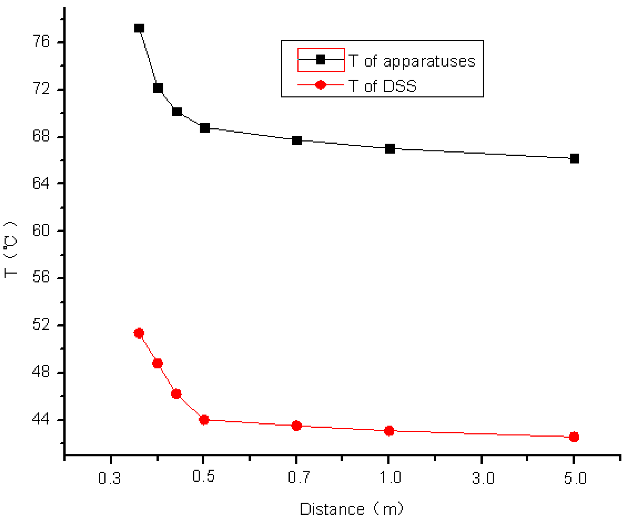
In the paper, a model of a DSS in Chongqing (containing two dry-type transformers and switchgears) was set up first, and the temperature field distribution was calculated. Then factors influencing the temperature field distribution were studied, and the influence of different factors was computed and discussed. When the distance between the apparatus and wall exceeds 3 m, the temperature change in the DSS is very small. Therefore considering the floor area of the DSS, 3 m is the best between the apparatus. With any change of the environment temperature or the velocity of the ventilation fans, the maximum temperature in the DSS or apparatus will change, therefore an energy saving ventilation strategy is proposed in this paper, and an intelligent cooling control system is developed, which can modify the wind velocity of the ventilation fans according to the environment temperature, which can result in energy savings.
The remainder of the paper is organized as follows:
Section 2 presents the calculation of temperature field in the DSS, including the setup of model, calculation of heat losses in the transformers and switchgears, and setting of boundary conditions.
Section 3 will describe the study on the factors influencing the heat distribution. This section also shows the influence on the distribution of temperature field caused by different factors. The intelligent cooling control system for urban DSS mentioned in this paper will be explained in
Section 4. Finally, concluding remarks will be given in
Section 5.
2. Calculation of the Temperature Field in an Urban Distribution Substation
2.1. Physical Model Setup
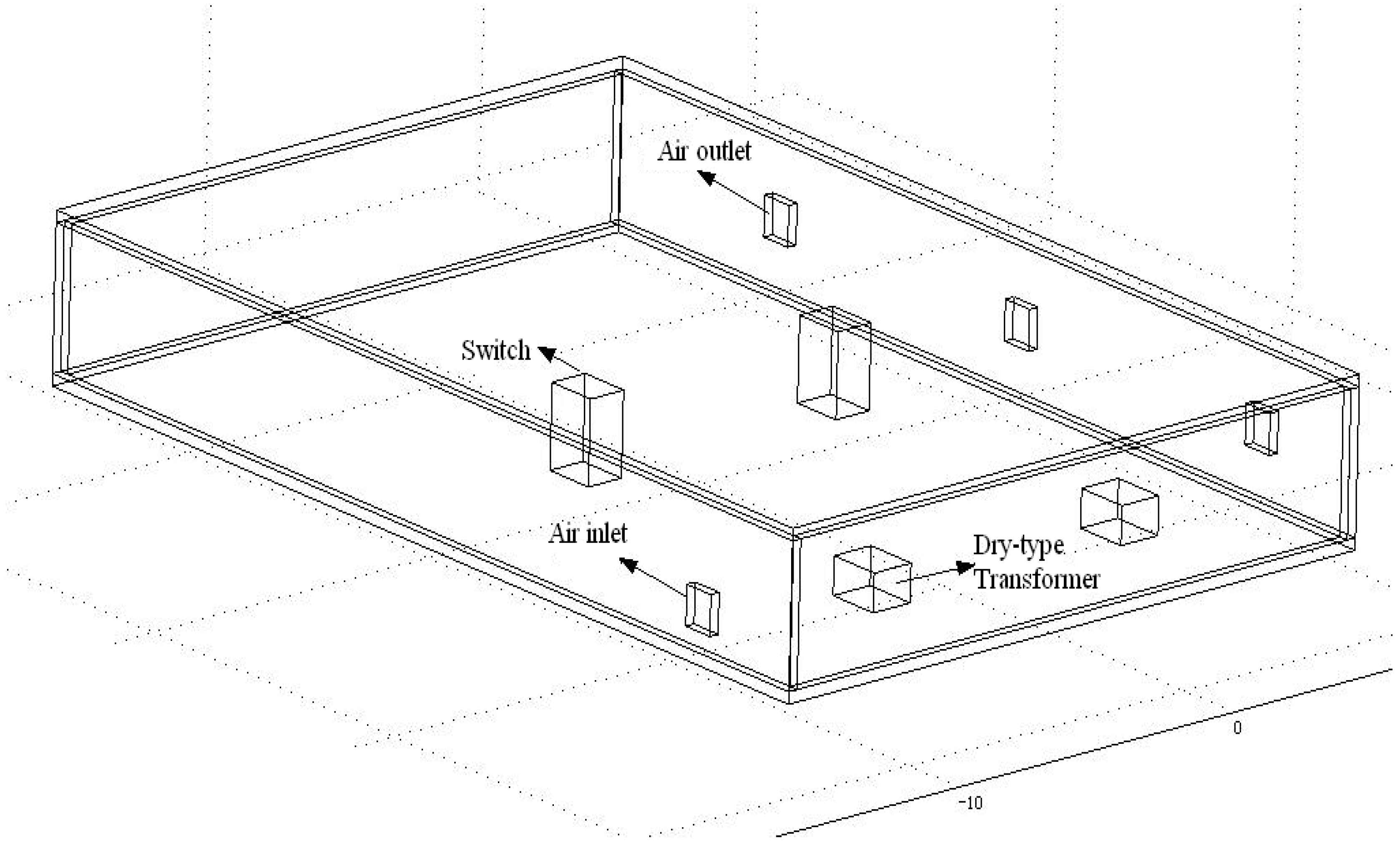
A DSS in Chongqing is taken as an example for the study. In this DSS there are 2 dry-type transformers, two HV switchgears and a few bus bars. Because the heat loss on the bus bars is much less than the loss in the dry-type transformers and HV switchgears, therefore, to simplify the calculation, the bus bars were ignored in the model, as shown in
Figure 1.
Table 1 shows the dimensions of the model. The dry-type transformer is a SCB10-1250/10 type, with a rated capacity of 1250 kVA, high-voltage side of 10.5 kV, low-voltage side of 0.4 kV, load loss of 9300 W, and no-load loss of 2500 W. For the HV switchgears, the total loss is 560 W. The distance between the transformer and the HV switchgear is 12 m, the distance between two transformers is 9 m. The air inlet and the two transformers are located in the same line. In the calculation, the environmental temperature is 38 °C.
Figure 1.
Physical model of the DSS (two transformers, two HV switchgears, one air inlet and two air outlets are considered in the model).
Figure 1.
Physical model of the DSS (two transformers, two HV switchgears, one air inlet and two air outlets are considered in the model).
Table 1.
Size of objects in the model.
Table 1.
Size of objects in the model.
| Name | Size (Length, Width, Height) |
|---|
| DSS house | 20 m × 10 m × 3.6 m |
| Transformer | 1.67 m × 1.34 m × 0.95 m |
| Switchgear | 1.62 m × 1.23 m × 1.81 m |
2.3. Heat Dissipation of Apparatus in the DSS
The main modes of heat dissipation of the transformers and switchgears in the DSS include heat radiation and heat convection. Heat convection includes natural-convection and forced-convection [
5,
6]. The natural-convection heat transfer occurs mainly on the surface of the switchgears and transformers without exposure to ventilating fans. The forced-convection heat transfer occurs mainly within the radiation range of the ventilating fans.
(1) Heat radiation transfer:
If the wall temperature is
Tw and the environmental temperature is
Tf, then the heat quantity of the heat radiation transfer can be calculated as follows:
where
Ar is the area of radiation surface (m
2),
ε is the radiance on the radiation surface. For common steel plate,
ε = 0.820.
(2) Heat convection transfer:
The heat quantity of heat convection can be calculated according to Equation (3):
where:
h is coefficient of the heat convection, here ;
Φc is heat quantity of the heat convection (W);
Nu is Nusselt number characterizing the property of the heat convection;
l is characteristic length;
λ is heat conductivity of air (W·m−2·K−1);
A is area of the heat convection (m2);
Tw is wall temperature (°C);
Tf is air temperature (°C);
For the natural-convection heat transfer:
where
Pr is the Prandtl number,
Gr is the Grashof number,
C and
n are constants.
The natural convection occurring on the surface of the dry-type transformer can be regarded as the natural convection occurring on a vertical plate in infinite space. The values of
C and
n in Equation (4) are shown in
Table 2.
Table 2.
Value of C and n for natural convection occurring on vertical plate in infinite space.
Table 2.
Value of C and n for natural convection occurring on vertical plate in infinite space.
| Flow Pattern | C | n | Application Scope of Gr |
|---|
| laminar flow | 0.59 | 0.25 | 1 × 10⁴~3 × 10⁹ |
| transient state | 0.0292 | 0.39 | 3 × 10⁹~2 × 10¹⁰ |
| turbulence flow | 0.11 | 1/3 | >2 × 10¹⁰ |
For the forced-convection heat transfer occurring on the surface of the apparatuses,
Nuf can be calculated as follows:
where
Re =
ul/
v,
Re is the Reynolds number,
u is the air velocity (m/s), and
ν is the kinematic viscosity (in m
2/s). The values of
C and
n refer to the values in [
4], which are obtained from wind-tunnel tests.
2.4. Control Equations
The temperature field inside the DSS is a temperature field containing heat sources, so the control equation can be formulated as follows [
7,
8]:
where
qv is the heat rate in unit volume.
2.5. Setting of the Boundary Conditions
For the steady-state temperature field calculated in this paper, the boundary condition for convection is the typical second boundary condition. That is:
For this model, the calculated equivalent heat source of the transformer is 220.93 W/m3, and the equivalent heat source of a HV switchgear is 166.36 W/m3. The convection heat transfer coefficient is 10.87 when the wind velocity is 5.55 m/s. The radiation factor is 0.6. Considering the hot summers in Chongqing, an environmental temperature of 38 °C is assumed in this model.
2.6. Distribution of the Temperature Filed in the Objective DSS
Ventilation fans were installed in the DSS shown in
Figure 1. The parameters of the intake fan are as follows: the rotational speed (
n) is 1450 r/min, the wind rate is 6178 m
3/h, and the wind pressure is 138 Pa. The wind rate of the exhaust fans is 2000 m
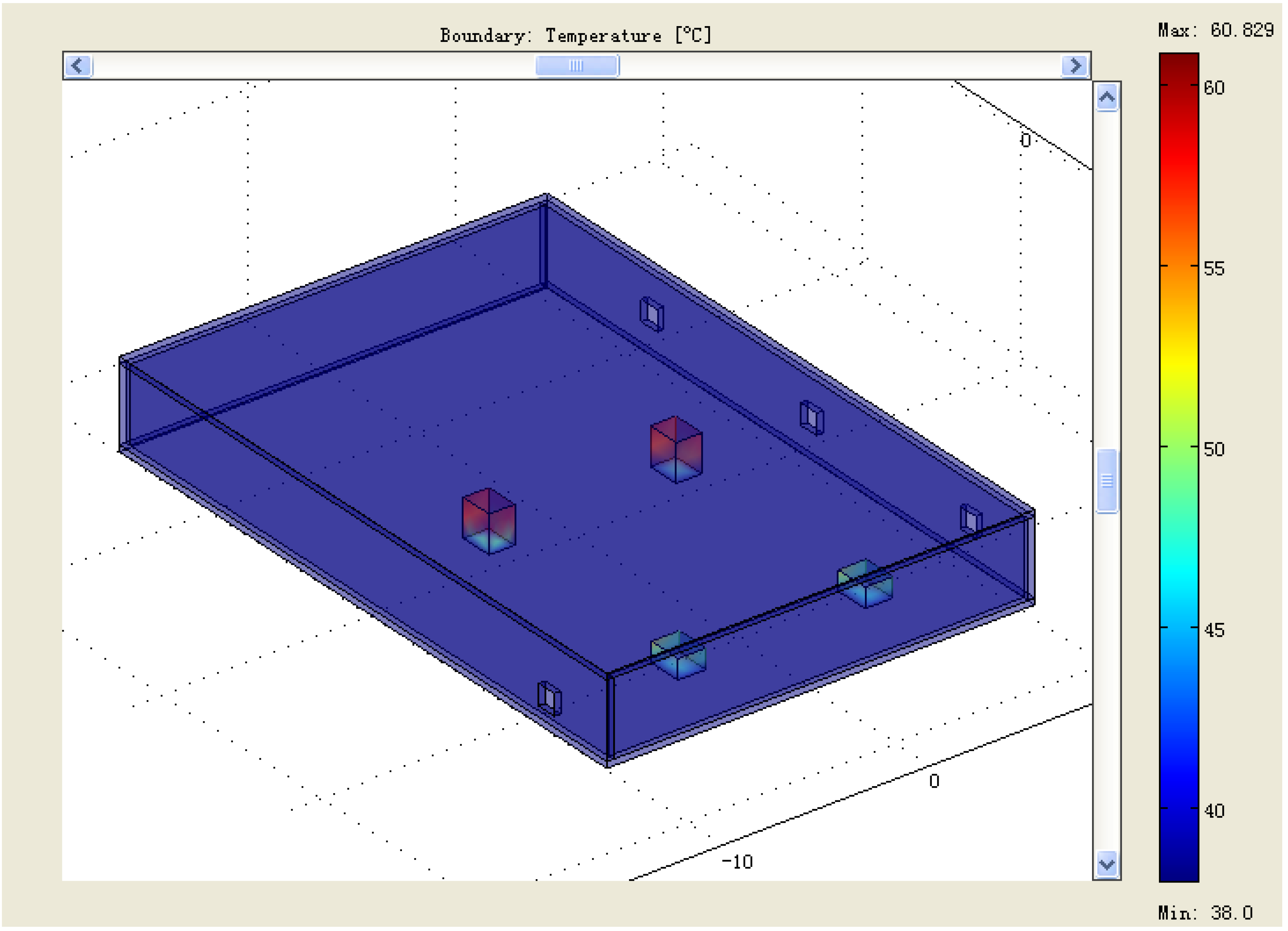
3/h. According to the boundary conditions mentioned above the temperature field distribution in the DSS was computed, and the result is shown in
Figure 2. The maximum temperature of the transformers and the switchgears is 60.829 °C, and the maximum temperature of the air in the DSS is 40.057 °C, which means the transformers and switchgears are under safe operation conditions.
At present the ventilating fans operate day and night to ensure the apparatus operate safely, however the environmental temperature decreases during the night, so if same ventilating fans were used during the daytime and at night or during different seasons, energy waste will result when the environmental temperature is lower than the temperature in summer. Hence it is necessary to find an intelligent strategy for the cooling system. For this purpose, first of all, the factors affecting the distribution of temperature field in the DSS were investigated.
Figure 2.
Temperature field distribution in the studied DSS.
Figure 2.
Temperature field distribution in the studied DSS.
4. Intelligent Cooling Control System
According to the influence of the environmental temperature on the temperature field distribution in the DSS shown in
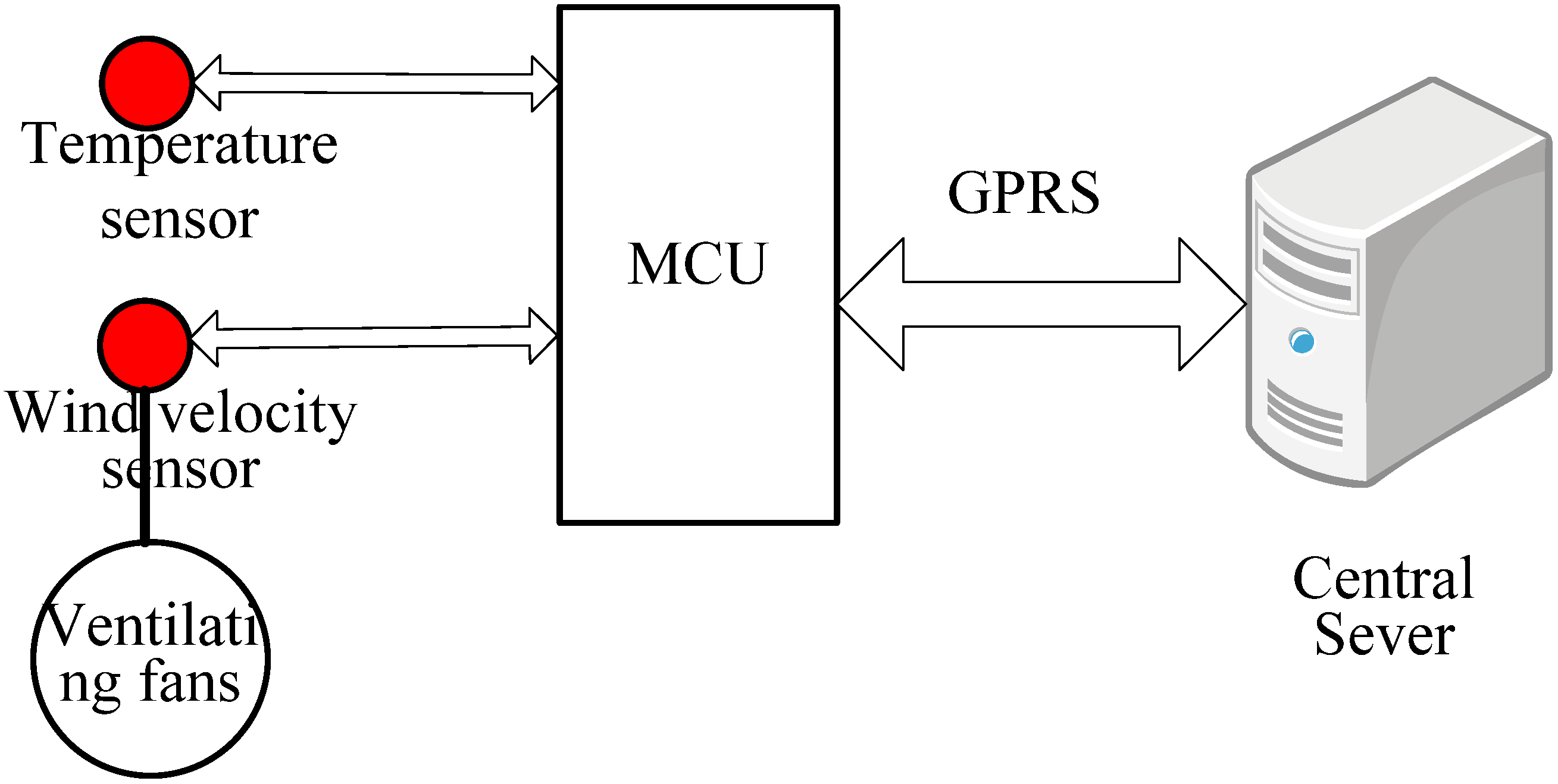
Figure 1, an intelligent cooling control system was set up, and an energy-saving ventilation strategy was implemented, which means that for different environment temperatures, the wind velocity of the ventilation fan is different. This energy-saving cooling strategy is shown in
Table 5, while
Figure 5 shows the schematic diagram of the system.
As shown in
Figure 5, the control system is composed of a central sever and a control terminal. A temperature sensor was used to measure the environmental temperature, and according to the measured environmental temperature, the MCU modifies the velocity of the ventilating fans in operation, hence for different environment temperatures the power-consumption for the ventilation fans is different, which can save energy compared with the current strategy, in which the ventilating fans always operate at the same velocity. The operational status of the apparatus are sent to the central sever by GPRS. This intelligent control system is now in operation in this DSS.
Table 5.
Energy-saving cooling strategy.
Table 5.
Energy-saving cooling strategy.
| Environment Temperature(°C) | Wind Velocity (m/s) |
|---|
| 10 | 1.7 |
| 20 | 2.3 |
| 30 | 4.6 |
| 38 | 5.5 |
Figure 5.
Schematic diagram of the intelligent cooling control system.
Figure 5.
Schematic diagram of the intelligent cooling control system.


