Article

Balancing Control Strategy for Li-Ion Batteries String Based on Dynamic Balanced Point

1
School of Information Engineering, Wuhan University of Technology, Luoshi Road 122, Wuhan 430070, China
2
School of Automation, Wuhan University of Technology, Luoshi Road 122, Wuhan 430070, China
3
Wuhan Zhongyuan Electronic Information Company, Luoyu East Road 6, Wuhan 430074, China
4
The Electrical Engineering College, Guizhou University, Huaxi, Guiyang 550025, China
*
Author to whom correspondence should be addressed.
Energies 2015, 8(3), 1830-1847; https://doi.org/10.3390/en8031830
Submission received: 20 November 2014 / Revised: 23 January 2015 / Accepted: 6 February 2015 / Published: 4 March 2015

Abstract

:
The Li-ion battery is becoming the optimal choice for the Electric Vehicle’s (EV) power supply. In order to protect the Li-ion battery from charging damage and to prolong the battery’s life, a special control strategy based on the dynamic balanced point along with a non-dissipative equalizer is presented. The main focus of the proposed control strategy is to insure that the individual cell of a battery pack will be rapidly, efficiently and simultaneously balanced, by adjusting equalizing current of each cell dynamically. In this paper, a model of a four series connected Li-ion batteries pack has been established to evaluate the proposed control strategy. Superior performance is demonstrated by the simulation and experiment.

1. Introduction

With the increased energy crisis and environmental pollution, new energy vehicles, such as electric vehicles (EV), based on their low-consumption and minimum pollution, have become the emerging direction of the automotive industry. It is anticipated that the lithium-ion battery as the energy storage will be widely used, because of its high energy and power densities, long cycling life and good cost performance [1].
The nominal voltage of a lithium-ion cell is about 3.65 V. In order to meet the demand of an EV, dozens of lithium-ion cells are usually stacked and connected in series. Nevertheless, connected serially brought lithium-ion battery pack some issues, especially inconformity of cells [2]. As a result of the limitation of manufacturing technology, each cell from a battery string is not equal to the others, in terms of capacity, voltage and internal resistance. Due to the inconsistency, cells from a battery pack will be over-charged or over-discharged, meanwhile the performance and lifecycle of the entire battery pack will be dropped significantly, and worst of all, that may cause a fire or explosion [3]. Therefore, it is absolutely necessary to employ a cell equalizer, which is far more feasible than developing manufacturing technology, in order to eliminate the cell unbalancing.
Nowadays, a lot of equalization structures and balancing strategies have been proposed [4,5,6,7,8,9,10,11,12,13,14,15,16,17,18], and summarized in [2,15]. In considerations of energy consumption and transformation, they can be divided into dissipative balancing circuits [4] or non-dissipative balancing circuits [5,6,7,8,9,10,11,12,13,14,15,16,17,18]. Dissipative balancing circuits violate the future trend of energy-saving, although it is practical with simple topologic and convenient control strategy. According to the charge transfer structure, non-dissipative balancing circuits can be classified into three methods: pack-to-cell balancing methods [6,7,8,9,10,11], a direct cell-to-cell method [12,13,14] and an adjacent cell-to-cell method [15,16,17]. The pack-to-cell balancing methods and direct cell-to-cell generally show outstanding balancing performance and speed due to direct charge transfer. However, because of the difference in the reference voltage between each cell in the battery pack, the aforementioned balancing circuits should use transformers for galvanic isolation or many bidirectional switches. Moreover, most bidirectional switches require a floating gate driving circuit due to different reference voltages, and their voltage stress is relatively high in order to withstand the battery pack voltage. As a result, the aforementioned balancing circuits have bulky size and high implementation cost. On the other hand, adjacent cell-to-cell balancing circuits can be competitive candidates for cost-effective circuits with a small size because of low voltage stress of all of the switches and diodes. Thus, the buck-boost converter [19] included as one of the adjacent cell-to-cell methods is quoted in this paper.
Relatively complex circuits limit the deployment for rapidity, stability or efficiency. To solve the deficiency, utilization of a high-performance control strategy [20,21,22,23] is essential. Fuzzy control [18] is beneficial to reduce balancing time, while Proportional Integral (PI) control [20] is an effective method to improve balancing accuracy. In order to integrate the advantages of control methods above, a Fuzzy-PI control has been shown in [20]; however, it is complex. Almost all of the control strategies are in PFM (pulse frequency modulation) mode based on the voltage difference. However, it is difficult to design magnetic elements without a certain range of frequencies.
In this paper, a non-dissipative DC-DC (direct current) converter is applied as main circuit of the equalizer. The DC-DC converter will be optimized for maximized averaged current for the different positions of series connected lithium-ion battery. Meanwhile, in this paper, adoptive balancing frequency and associated control strategy were proposed, to furnish a theory for the design of components, and for achieving the fastest balancing speed. The optimized circuit parameters and the control strategy of pursuing dynamical balancing frequency will improve charging and discharging speed of batteries string. Furthermore, modularization using a layered balancing structure is appropriate for both EV’s power battery system and Smart Grid’s energy storage battery system.

2. Li-Ion Battery Equalizer Circuit

In order to satisfy the demands of large batteries string equalizer in EV applications, a layered balancing structure is adopted in which four cells constitute a bottom balancing module and four bottom balancing modules constitute an upper balancing module lowering the voltage stress and loss of switch components. The framework is shown in Figure 1.
Figure 1. Layered balancing structure.
Energies 08 01830 g001

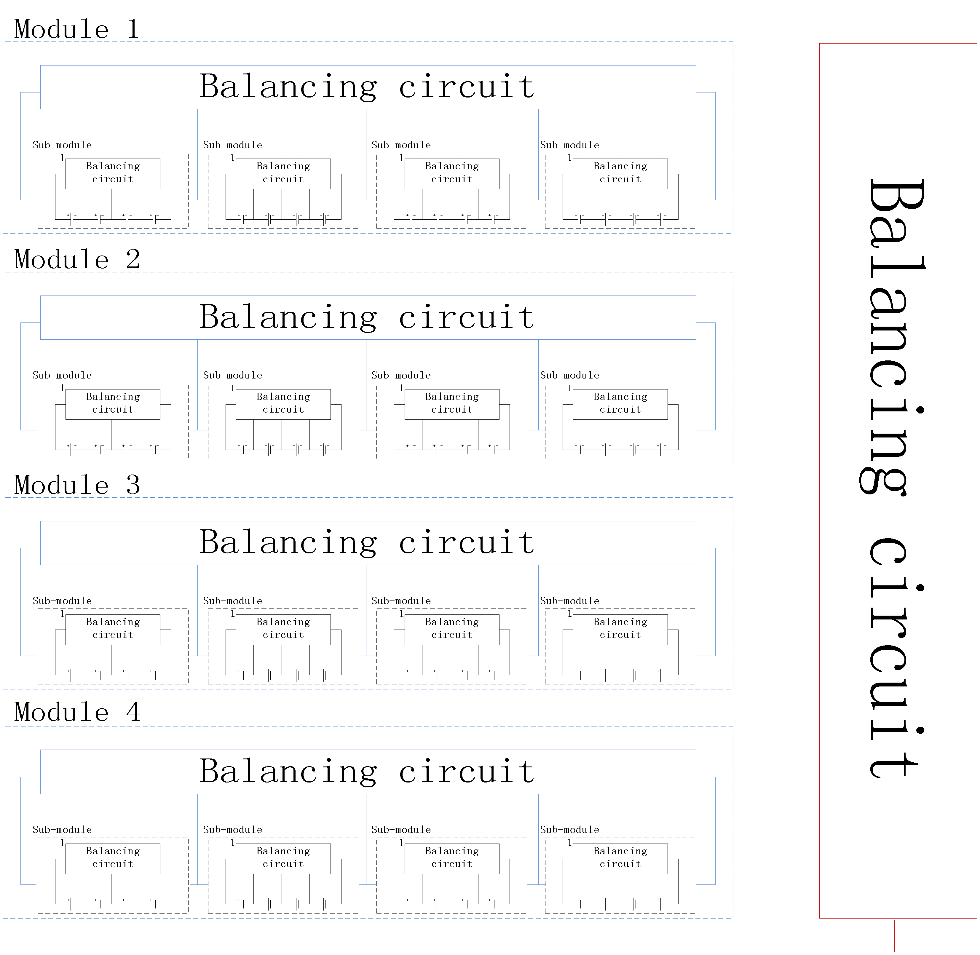
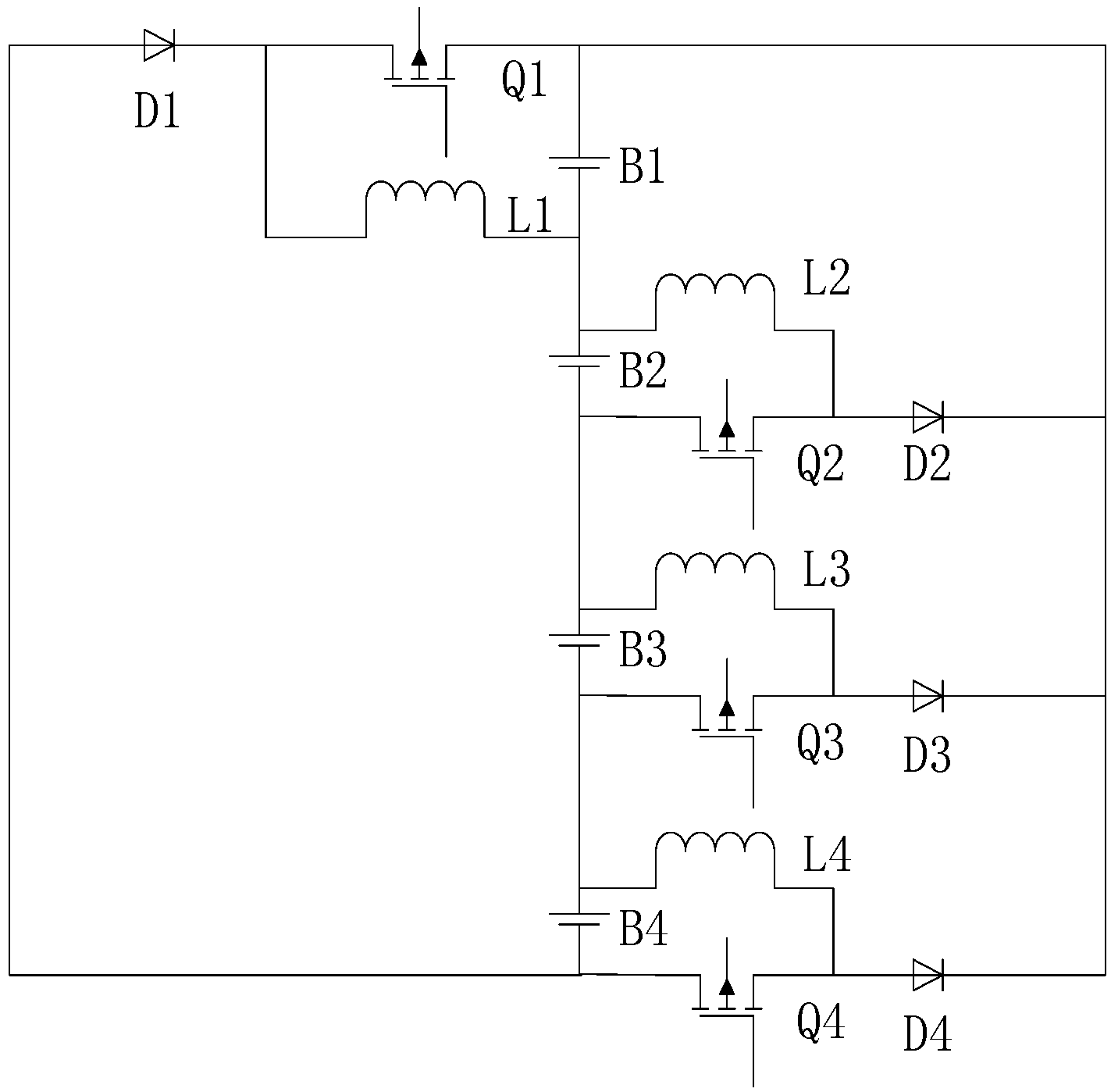
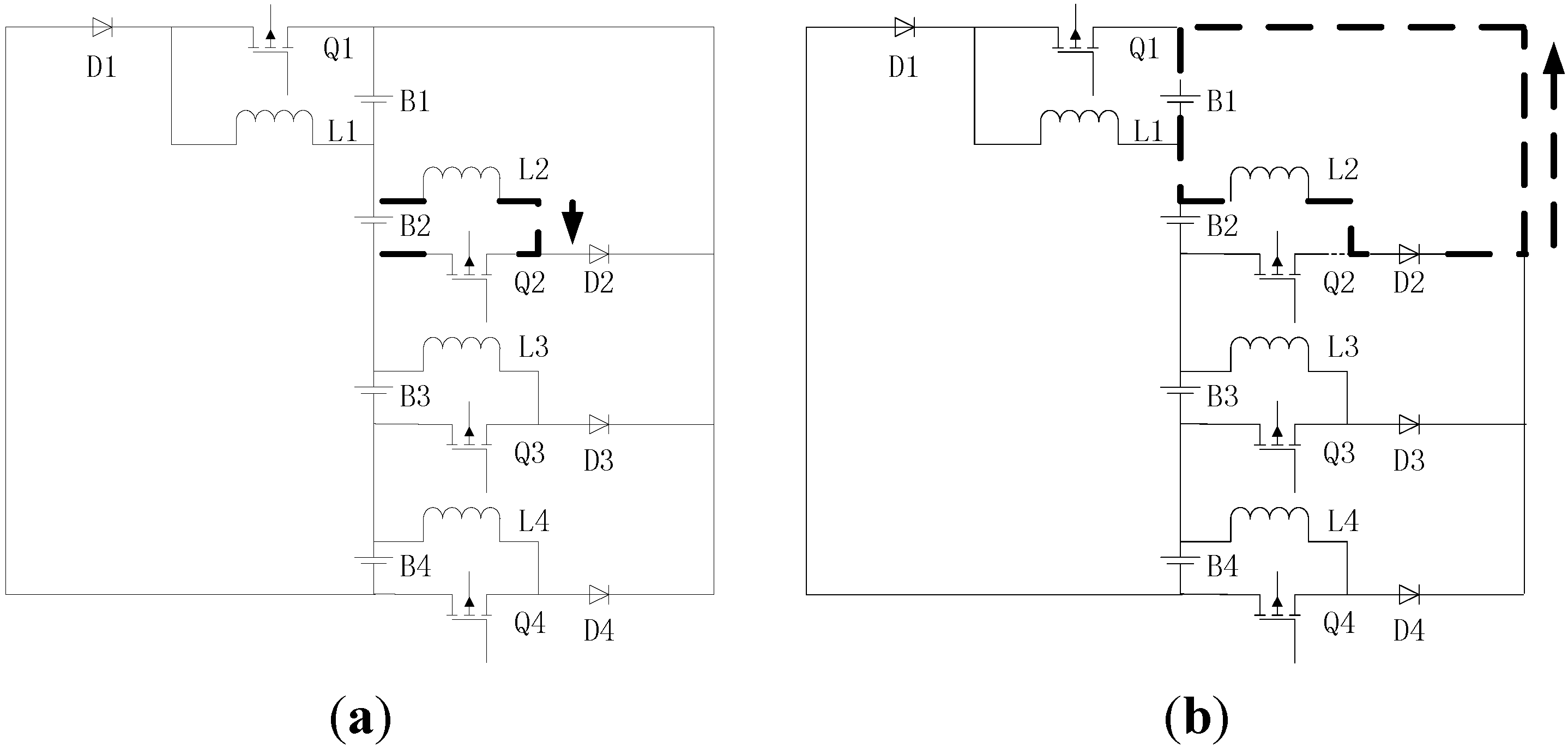
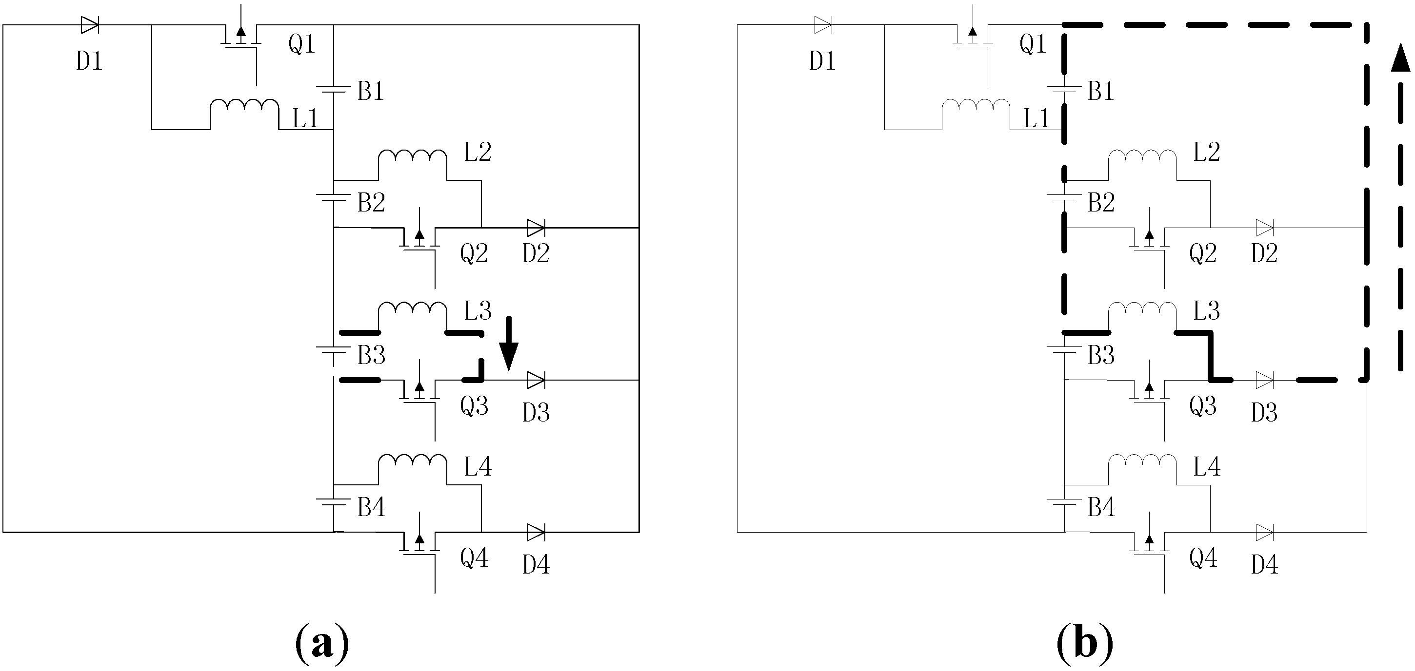
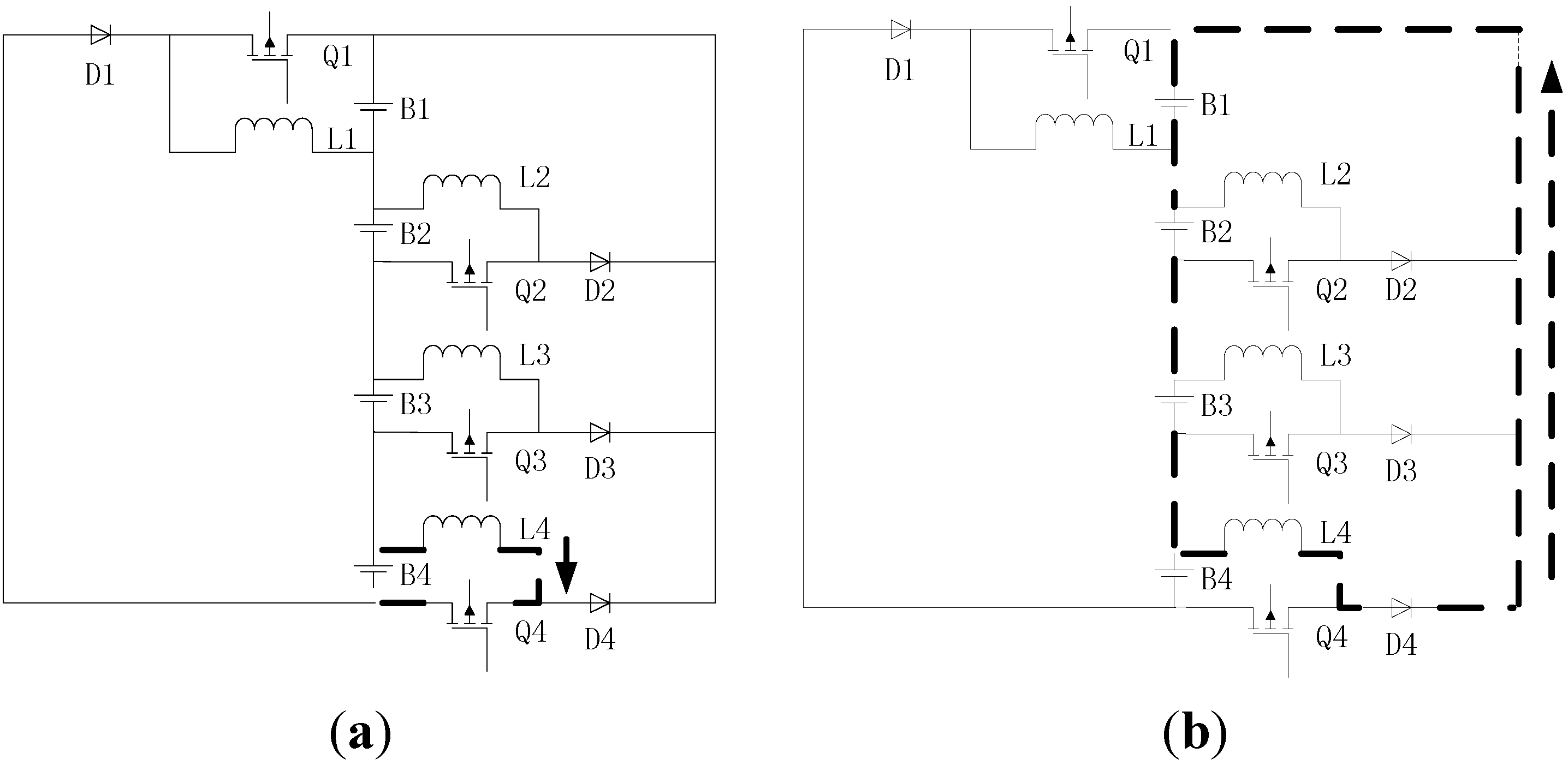
2.1. Circuit Description

Figure 2 depicts the DC-DC converter equalizer [19] which is the main circuit of battery equalization in this paper. Each of the cells Bn (n = 1, 2, 3, 4) is connected to a buck-boost converter with MOSFET (metal-oxide semiconductor field-effect transistor) Q n and energy storage inductor L n , and a commutating diode D n . The buck-boost equalizer has the ability to drive high current with less loss, because it uses only one MOSFET per cell.
Figure 2. Battery string with DC-DC converter equalizer.
Energies 08 01830 g002

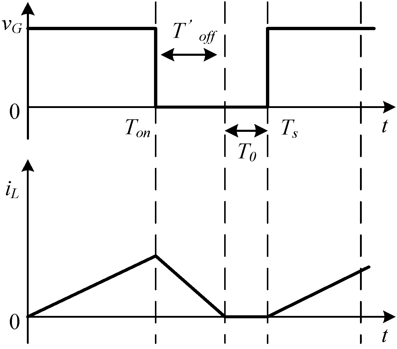
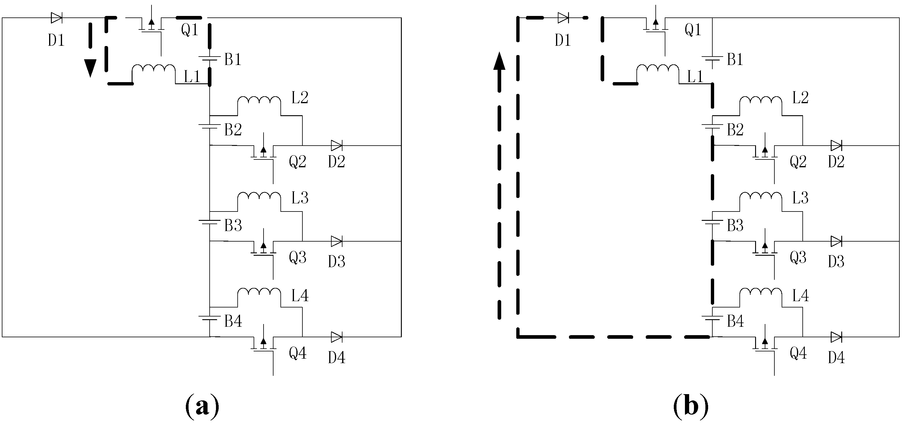
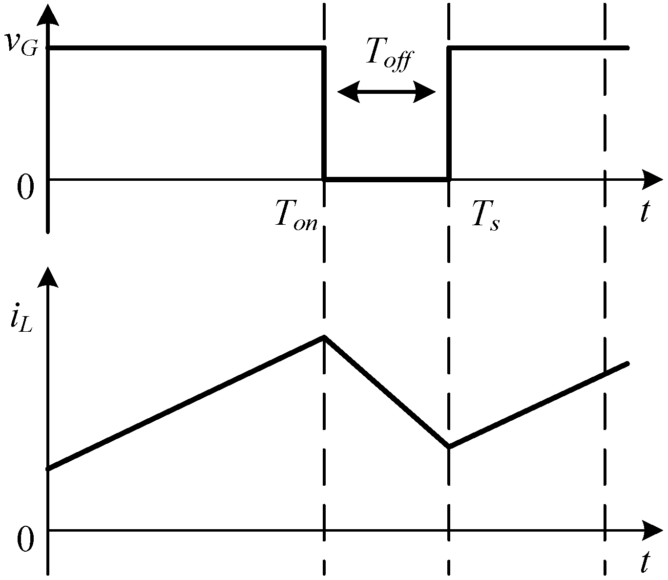
2.2. Operating Principle

Therefore, as to introduce the operating principle clearly and concisely, B 1 is taken as an example. As shown in Figure 3a, V ave is the average voltage of four cells. V B n is the voltage of each cell. When V B 1 is higher than V ave , Q 1 is on, current flows from B 1 to L 1 via Q 1 , meanwhile, excess energy of B 1 transferred and stored in L 1 . According to Figure 3b, when V B 1 is lower than V ave , Q 1 is switched off, current continued flows from L 1 to cells B 2 - B 3 - B 4 and the excess energy of B 1 transferred to B 2 - B 3 - B 4 successfully. Similar procedures are adapted to B 2 , B 3 and B 4 . In Figure 4, Figure 5 and Figure 6, excess energy of B 2 is transferred to B 1 , excess energy of B 3 is transferred to B 1 - B 2 , and excess energy of B 4 is transferred to B 1 - B 2 - B 3 . Thus, the switching frequency is controlled by the difference between V n and V ave in order to achieve equalization. The principle is to utilize inductors as energy carriers for transferring energy in order to achieve equalization.
Figure 3. Current path from B 1 to B 2 - B 3 - B 4 : (a) When Q 1 is switched on, current flows from B 1 to L 1 ; (b) When Q 1 is switched off, current flows from L 1 to cells B 2 - B 3 - B 4 .
Energies 08 01830 g003
Figure 4. Current path from B 2 to B 1 : (a) When Q 2 is switched on, current flows from B 2 to L 2 ; (b) When Q 2 is switched off, current flows from L 2 to cell B 1 .
Energies 08 01830 g004
Figure 5. Current path from B 3 to B 1 - B 2 : (a) When Q 3 is switched on, current flows from B 3 to L 3 ; (b) When Q 3 is switched off, current flows from L 3 to cells B 1 - B 2 .
Energies 08 01830 g005
Figure 6. Current path from B 4 to B 1 - B 2 - B 3 : (a) When Q 4 is switched on, current flows from B 4 to L 4 ; (b) When Q 4 is switched off, current flows from L 4 to B 1 - B 2 - B 3 .
Energies 08 01830 g006

3. Purposed Control Strategy

3.1. Dynamic Balanced Point

For each cell, energy flows out during the switch-on cycle, and then it absorbs energy from other cells during the switch-off cycle. In a state when cells of a battery string tend to be well balanced, it can be assumed that the energy that flows out from each cell is equal to the energy it absorbs. This state might be known as a dynamic balanced point. At a certain moment, if the charges of one cell are more than the average charges of the balancing module, the cell will only release charges; if the charges of one cell are less than the average charges of the balancing module, the cell will only receive charges. All the cells will be controlled to trace the balanced state of the average charges of the balancing module, and this balanced state is called the dynamic balanced point at that moment. Because any cell will only release or receive charges, this balancing method of tracing the dynamic balanced point will reduce the energy circulating from one cell to the other cell. Thus, this control strategy can reduce switching losses and accelerate the process of balancing.

3.2. Balancing Control Method

In this paper, a MCU (micro control unit) is employed to monitor the voltage across the cells and commanding a FPGA (field programmable gate array) to accomplish the energy transfer required by equalizer. The FPGA has been designed to provide PFM signal with fixed duty cycle until difference between highest cell voltage and average cell voltage is below 5 mV. The cooperation of MCU and FPGA makes it possible to apply the equalizer to the battery string of mass cells.

3.2.1. Duty Cycle Derivation

Continuous current mode (Figure 7) and discontinuous current mode (Figure 8) are two operating modes of a DC-DC converter. To avoid saturated hysteresis, the DC-DC converter should operate in discontinuous current mode in which inductors could completely release energy during the switch-off cycle. The derivation process of the condition that duty cycle must meet is as follows.
Figure 7. Continuous current mode.
Energies 08 01830 g007
Figure 8. Discontinuous current mode.
Energies 08 01830 g008
Taking Q n , n = 1 ,⋯,N, for example, the voltage across the inductor is marked as V B n when the switch is on. When the switch is off, the voltage across the inductor is marked V O n . As far as the first switch is concerned, V O n equals to the sum of all the following cell voltages. For the other switches, V O n equals to the sum of all the upper cell voltages. T n and T c r refers to switching period of Q n and the moment when the inductor current falls to zero, respectively.
The inductor current expression is as follows:
i L n = { V B n L n t   ,                                                                               0 t < D T n V B n L n D T n V O n L n ( t D T n )   ,   D T n t T c r 0 ,                                                                                           T c r t T n
As T n is greater than T c r and that inductor current is zero when t equals to T c r , the quantity [ V B n L n D T n V O n L n ( t D T n ) ] is less than zero when t equals to T n :
V B n L n D T n V O n L n ( T n D T n ) < 0
then:
D < V O n V B n + V O n = 1 V B n V O n + 1
Inequality (3) must be satisfied in order to ensure the converter operating in discontinuous current mode (DCM), no matter how the quantity V B n V O n is. According to the circuit structure, Inequality (3) can be classified in to four conditions as follows:
n = 1 , D < 1 V B 1 V B 2 + V B 3 + V B 4 + 1
n = 2 , D < 1 V B 2 V B 1 + 1
n = 3 , D < 1 V B 3 V B 1 + V B 2 + 1
n = 4 , D < 1 V B 4 V B 1 + V B 2 + V B 3 + 1
To simplify the control method, the duty cycles of the switches are the same in the whole circuit. In order to meet the inequalities (4)–(7), the minimum of duty cycle (D) should be taken, that is to say, V B n V O n should take its maximum in inequality (5). Since lithium-ion battery voltage range is from 2.5 to 3.65 V, we set V B 2 equals 3.65 V and V B 1 equals 2.5 V, then:
D < 1 3.65 2.5 + 1 = 0.4065
Therefore, the duty cycle must be less than 0.4065, in order to make sure that convertors operate in discontinuous current mode. In this paper, a duty cycle of 0.38 is used. Since the buck-boost circuit is stable when the duty cycle is less than 0.5 [24], the proposed circuit is stable giving duty cycle as 0.38.

3.2.2. Inductance Value Calculation

Since the amount of voltage delivered by B n can be expressed as V B n = L n d i d t , and { d i = Δ I n d t = D T n in DCM mode, the peak current of inductor, Δ I n , is given by:
Δ I n = V B n D T n L n = V B n D L n f n
where D is the duty cycle, and f n is the oscillation frequency of MOSFET.
The energy released from cell B n in a period is marked as W n . From the formula W = U I t , W n can be written as:
W n = 1 2 V B n Δ I n D T
substitute Equation (9) into Equation (10):
W n = V B n 2 D 2 2 L n f n 2
According to the operating principle, the energy variations in the cells during the state of dynamic balanced point, can be shown as in the following formulas:
{ W 1 ´ = W 2 + 1 / 2 W 3 + 1 / 3 W 4 W 2 ´ = 1 / 3 W 1 + 1 / 2 W 3 + 1 / 3 W 4 W 3 ´ = 1 / 3 W 1 + 1 / 3 W 4 W 4 ´ = 1 / 3 W 1
where W n ´ is the energy that cell B n absorbed in one period. Since W n ´ = W n , Equation (12) can be rewritten as:
{ V B 1 2 D 2 2 L 1 f 1 2 = V B 2 2 D 2 2 L 2 f 2 2 + 1 2 V B 3 2 D 2 2 L 3 f 3 2 + 1 3 V B 4 2 D 2 2 L 4 f 4 2 V B 2 2 D 2 2 L 2 f 2 2 = 1 3 V B 1 2 D 2 2 L 1 f 1 2 + 1 2 V B 3 2 D 2 2 L 3 f 3 2 + 1 3 V B 4 2 D 2 2 L 4 f 4 2 V B 3 2 D 2 2 L 3 f 3 2 = 1 3 V B 1 2 D 2 2 L 1 f 1 2 + 1 3 V B 4 2 D 2 2 L 4 f 4 2 V B 4 2 D 2 2 L 4 f 4 2 = 1 3 V B 1 2 D 2 2 L 1 f 1 2
Supposing that the cells have been well equalized at the dynamic balanced point, as a result, V 1 = V 2 = V 3 = V 4 and f 1 = f 2 = f 3 = f 4 . Hence, the relation of energy storage inductors can be derived with Equation (13) as:
{ L 2 = 3 2 L 1 L 3 = 9 4 L 1 L 4 = 3 L 1
Assuming that L 1 = 4   μH , values of the other inductors are as follows, L 2 = 6   μH , L 3 = 9   μH , and L 4 = 12   μH .

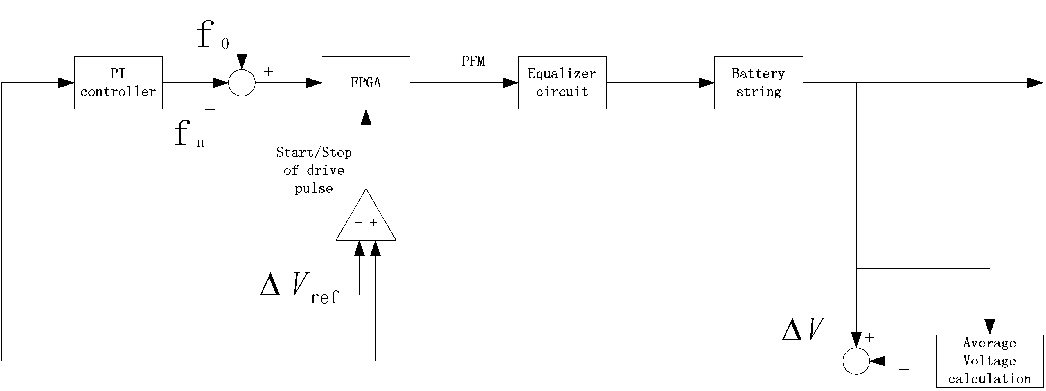
3.2.3. Control Algorithm

Obviously, it is more efficient and faster to equalize all cells at the same time. Hence, a PI control with PFM modulation is proposed for adjusting the balancing current, which is a direct method to enhance balancing speed. The structure of the control algorithm is shown in Figure 9. V n is the initial voltage of each cell. V ave is the average voltage of four cells. Δ V is the difference of V n and V ave . Δ V r e f is the reference voltage. f 0 is the dynamic balanced frequency. f n is the frequency when Δ V passes through the PI controller. The PI controller can reduce static error rapidly, which is beneficial to improve balance quality and guarantee balance speed.
Figure 9. PI controller block diagram.
Energies 08 01830 g009
According to Figure 9, if Δ V is higher than Δ V r e f , the FPGA works. At the same time, the PI controller sends the difference of f 0 and f n to the FPGA. Then the FPGA will drive the PFM signal to control the equalizer circuit and achieve equalization.
Judging by Equation (9), the balancing current is inversely proportional to the switching frequency. In other words, the more excess energy a cell has, the lower frequency it should take. However, in order to protect cells in the balancing circuit, the balancing current should be limited. In this paper, 5 A is the maximum average balancing current. When the purposed equalizer starts operating, every cell is releasing or absorbing energy continuously to approach the balanced point, however, the balanced point is changing dynamically because of the variation of cell voltage during charging or discharging.

3.2.4. Frequency Value Calculation

Since the inductor current has been expressed by Equation (1), average current of inductor during switch-on period which is denoted as I n , o n can be written as:
I n , o n = 1 T n 0 D T n V B n L n t d t = 1 T n V B n 2 L n [ ( D T n ) 2 0 ] = V B n D 2 T n 2 L n
At the switch-off period, average current of inductor which is denoted as I n , o f f can be written as:
I n , o f f = 1 T n D T n T ´ n [ V B n L n D T n V O n L n ( t D T n ) ] d t = V B n D 2 T n 2 L n ( V B n V O n )
As mentioned before:
{ V B n V O n V B 1 3 V B 1 = 1 3 ,   n = 1 V B n V O n V B 1 ( n 1 ) V B 1 = 1 n 1 ,   n 1
substitute Equation (17) into Equation (16):
I n , o f f = { V B n D 2 T n 2 L n * 3 ,   n = 1 V B n D 2 T n 2 L n * ( n 1 ) ,   n 1
According to Equations (15) and (18), the average current of inductor which is denoted as I n , a v and can be written as:
I n , a v = I n , o n + I n , o f f = { V B n D 2 T n 2 L n * ( 1 + 1 3 ) ,   n = 1 V B n D 2 T n 2 L n * ( 1 + 1 n 1 ) ,   n 1
In this paper, in order to meet the customer’s demand for balancing speed, we suppose that the average balancing current is 3 A, so the frequency can be given as follows:
{ f 1 = 29.281   kHz f 2 = 29.281   kHz f 3 = 14.641   kHz f 4 = 9.760   kHz
As mentioned, balancing current is inversely proportional to the frequency. However, excessive current will lead to an excessive releasing or excessive absorption of energy during one switching period. In order to remedy this, more energy should be absorbed or released in other periods. Hence, the efficiency will be decreased as a result of the many energy transformations. By considering both balancing speed and efficiency, we choose the average frequency among f 1 - f 2 - f 3 - f 4 as the dynamic balanced frequency, which is chosen as f 0 = f ave = f 1 + f 2 + f 3 + f 4 4 = 20.741  kHz . Since the frequency varies within a narrow range from f 4 to f 1 , the effect of frequency can be ignored when designing the filter.

4. Simulation Performance

In this section, the propose equalizer and controller have been simulated in order to test the performance of equalization in Simulink of Matlab 2010B. Test condition includes ideal components and battery model. It is important to note that the simulation is aimed to give a qualitative analysis for the feasibility; hence, the model of battery is simply built with a series connected resistor and capacitor; in addition, the ideal components have been applied as well. Table 1 shows the initial parameters of four lithium-ion cells. Considering that the simulation time is limited, the capacity of lithium-battery model is smaller than the actual. Duty cycle and inductors have been given in Section 3.
Table 1. Cell Parameters.
BatteryB1B2B3B4
Capacitance500 μF500 μF500 μF500 μF
Resistance0.5 mΩ0.5 mΩ0.5 mΩ0.5 mΩ
Initial voltage3.40 V3.00 V2.90 V3.30 V
Maximum voltage difference0.50 V

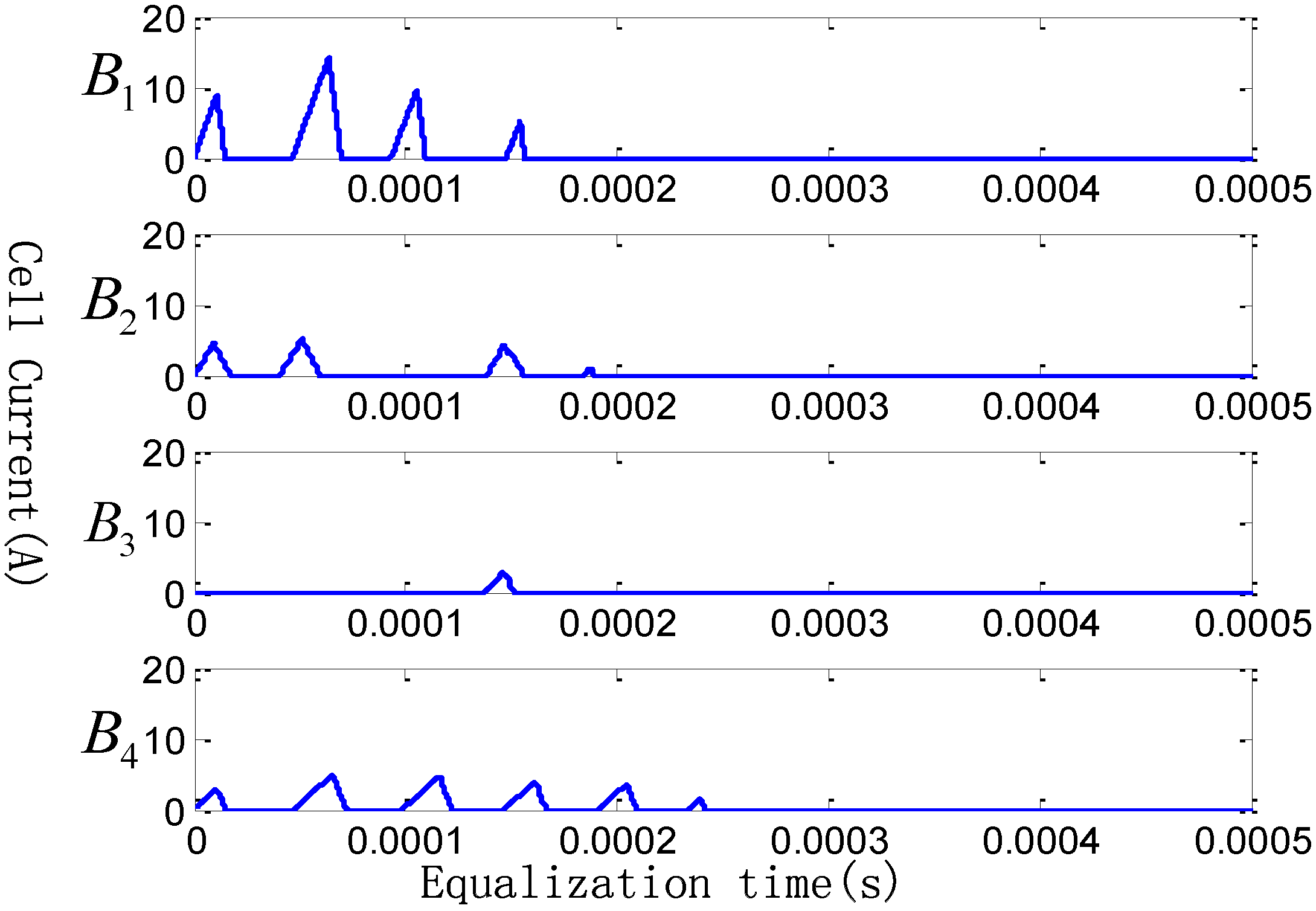
4.1. Balanced Frequency Analysis
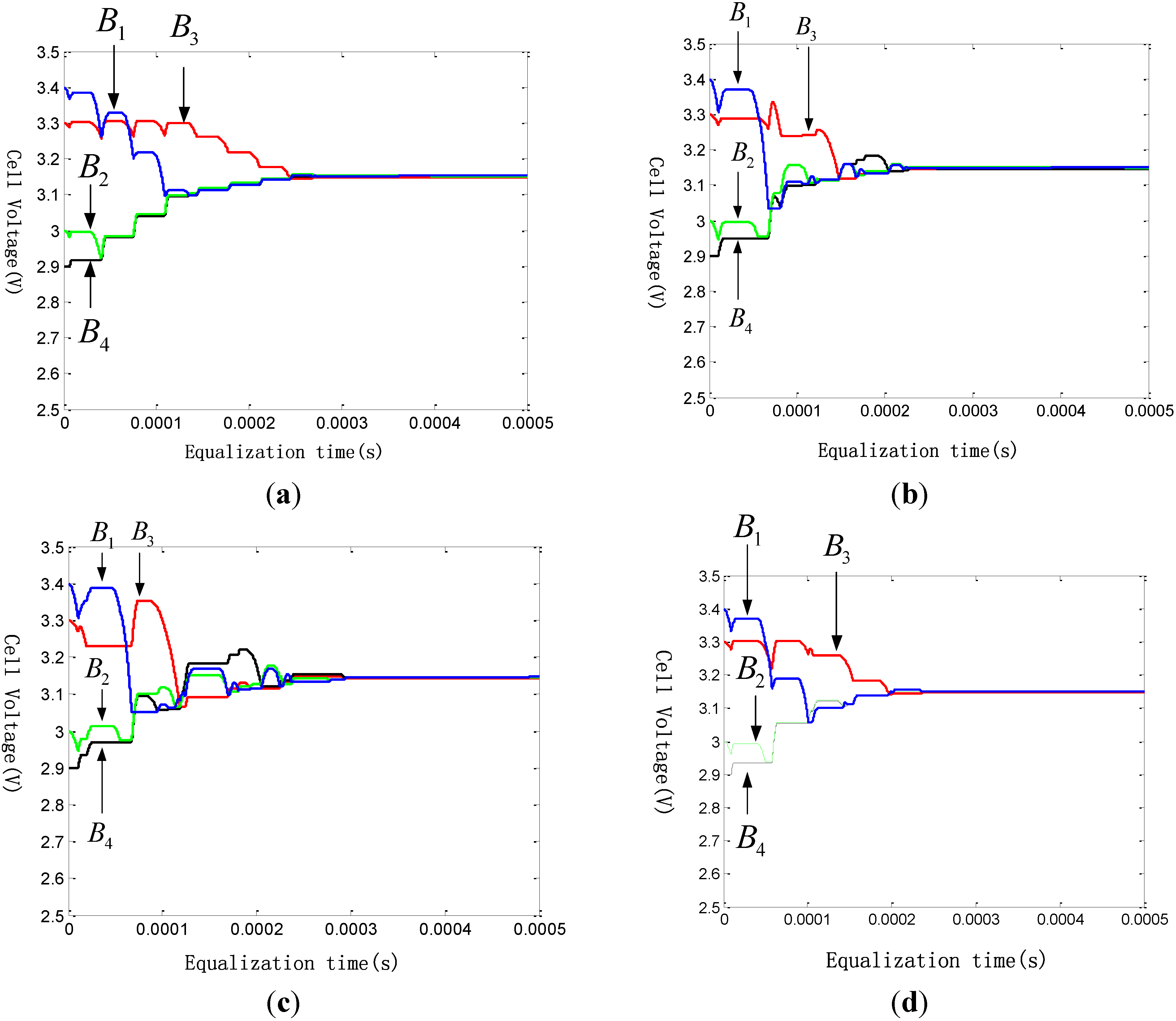
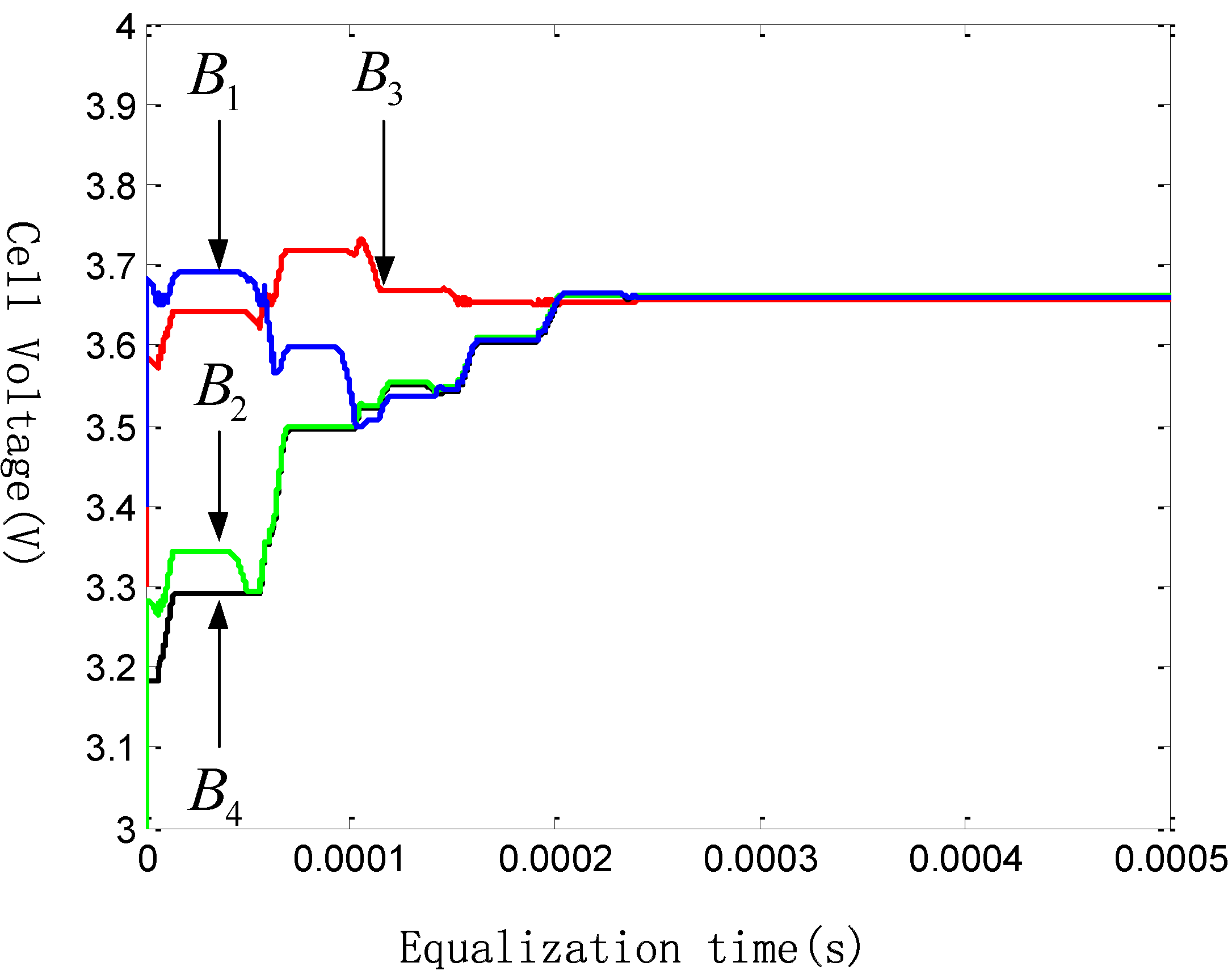
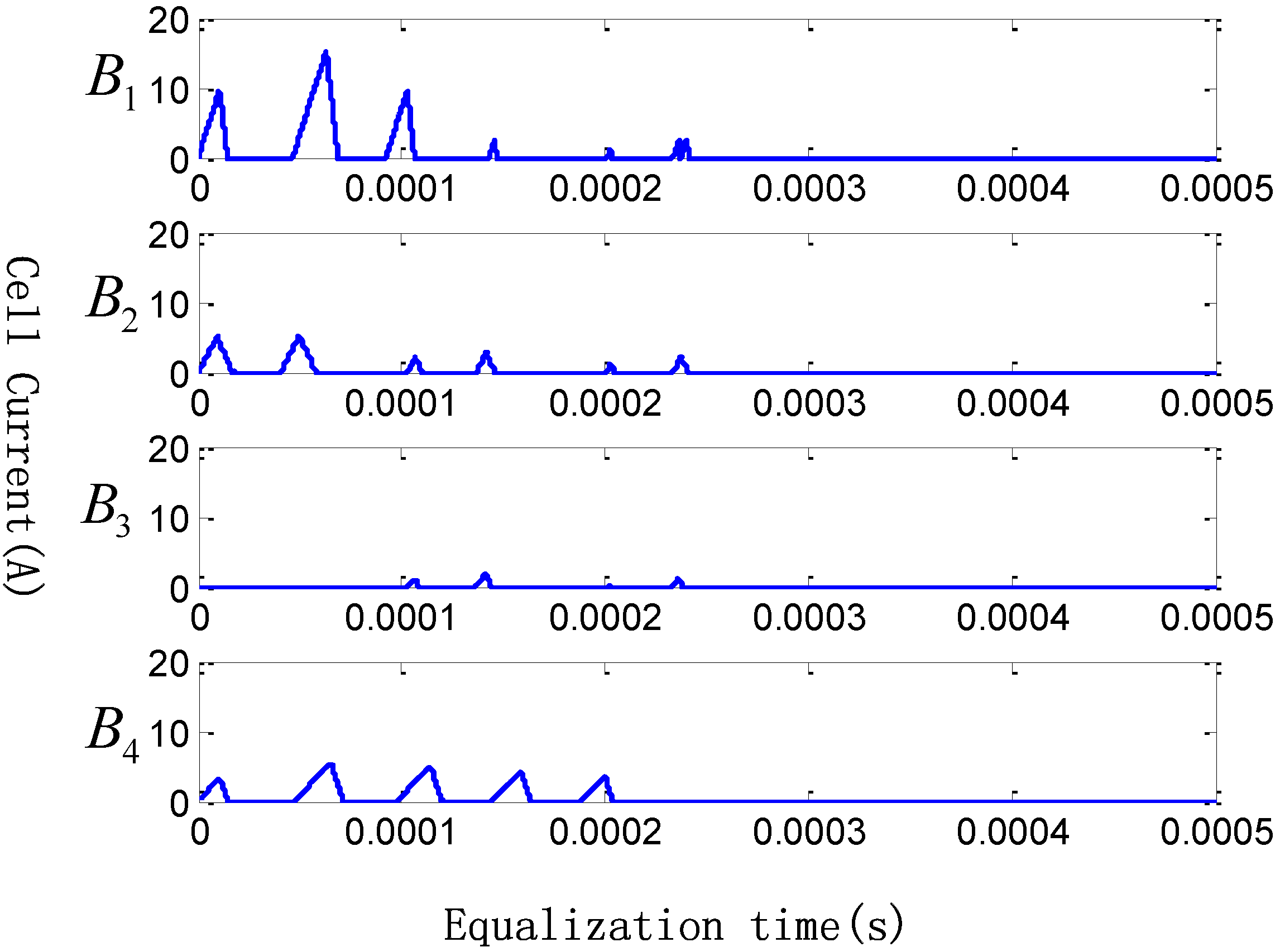
According to Equation (20), Figure 10a shows the static state when f a = f 1 = f 2 = 29.281   kHz is chosen as the dynamic balanced frequency f 0 . Figure 10b–d shows the static balancing process with different balanced frequency f 0 , among which are f b = f 3 = 14.641   kHz , f c = f 4 = 9.760   kHz , and f d = f a v e = 20.741   kHz . As expected, the simulation performance of Figure 10d is the best with less switching periods and higher speed. Hence, we applied f 0 = f d = f a v e = 20.741   kHz as the dynamic balanced frequency definitely, which has been mentioned in Section 3.
Figure 10. Cell voltages during static state with different balanced frequency: (a) Cell voltages during static state when dynamic balanced frequency f 0 = 29281 Hz; (b) Cell voltages during static state when dynamic balanced frequency f 0 = 14641 Hz; (c) Cell voltages during static state when dynamic balanced frequency f 0 = 9760 Hz; (d) Cell voltages during static state when dynamic balanced frequency f 0 = 20741 Hz.
Energies 08 01830 g010

4.2. Charging State

In charging state, a 16 V DC voltage source is applied in simulation. The initial voltages from batteries string are shown in Table 1. According to the characteristic of lithium-ion battery, we set 3.65 V as the charge voltage limit (CVL). Figure 11 shows the variation of cell voltages during equalization with 0.50 V initial maximum difference. Successfully, all cells have been well balanced with the difference between maximum and the minimum voltage is less than 5 mV. It is important to note that the battery model applied in this section is imperfect, and for this reason, the variation rate of battery voltage is abnormal. Especially for the charging process, cell voltages have suddenly increased by about 0.25 V at the beginning; however, it does not impact the simulation for qualitative analysis.
In order to observe the balancing current of each cells during equalization, Figure 12 is captured and presented. Balancing current is directly proportional to the difference of cell voltage. Meanwhile, cell voltages can be well balanced by only a few switching periods.
Figure 11. Cell voltages during charging state.
Energies 08 01830 g011
Figure 12. Balancing currents during charging state.
Energies 08 01830 g012

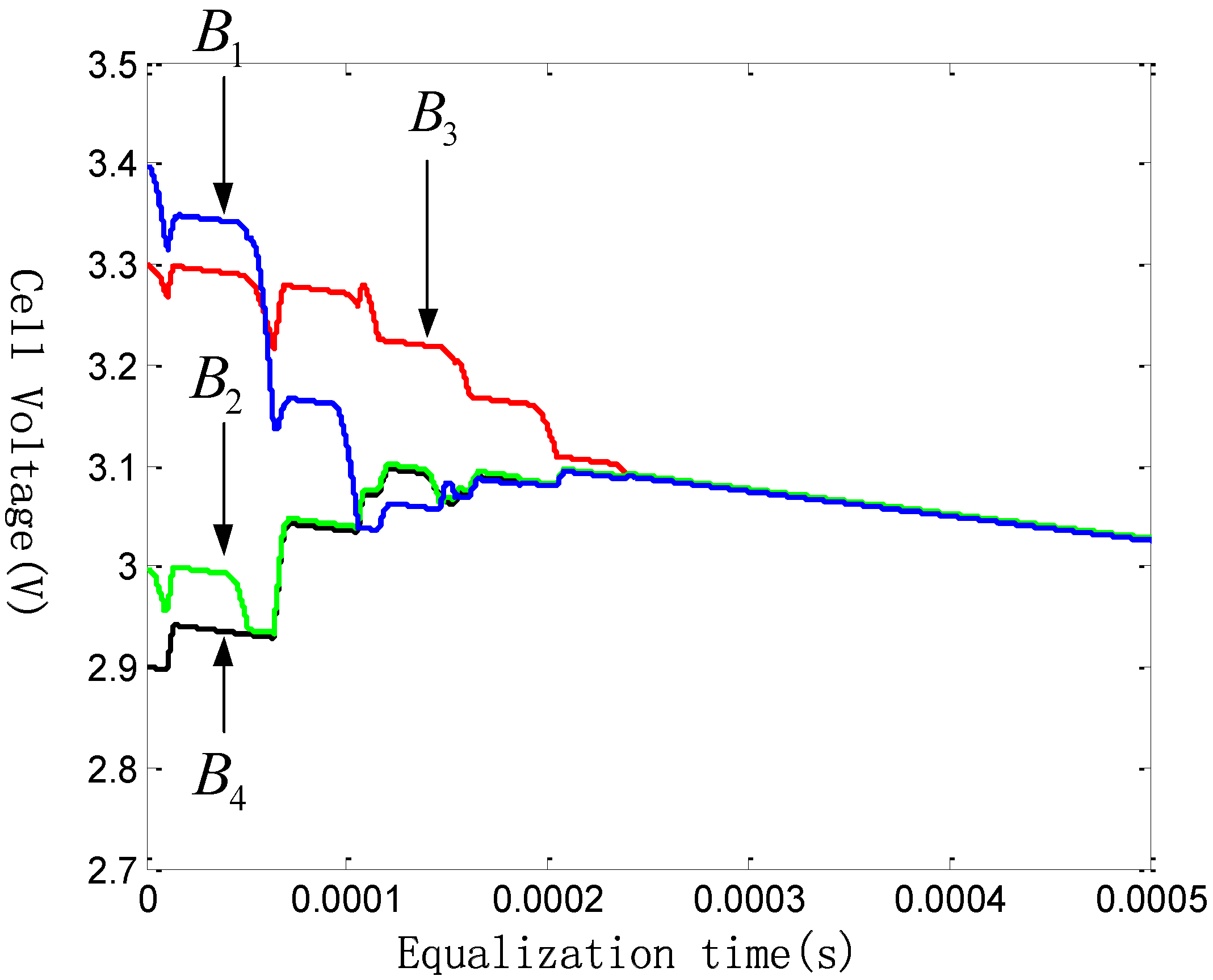
4.3. Discharging State

In discharging state, a 100 Ω resistance is serially connected to the batteries string which is served as load in simulation. Simulation condition is consistent with charging state, while discharge voltage limit (DVL) is 2.5 V. Figure 13 shows the variation of cell voltages during equalization with 0.50 V initial maximum difference. All cells have been successful balanced with the difference between maximum and minimum voltage is less than 5 mV as well. Figure 14 is given to show the balancing current.
In general, the purposed control strategy is able to realize equalization both in charging process and discharging process. Meanwhile, voltage difference between cells can be limited to 5 mV, successfully. Most of all, introducing the dynamic balanced point with PI control, the purposed equalizer can realize cells equalization by only a few switching periods, which is able to reduce switching losses and accelerate balancing speed as well.
Figure 13. Cell voltages during discharging state.
Energies 08 01830 g013
Figure 14. Balancing currents during discharging state.
Energies 08 01830 g014

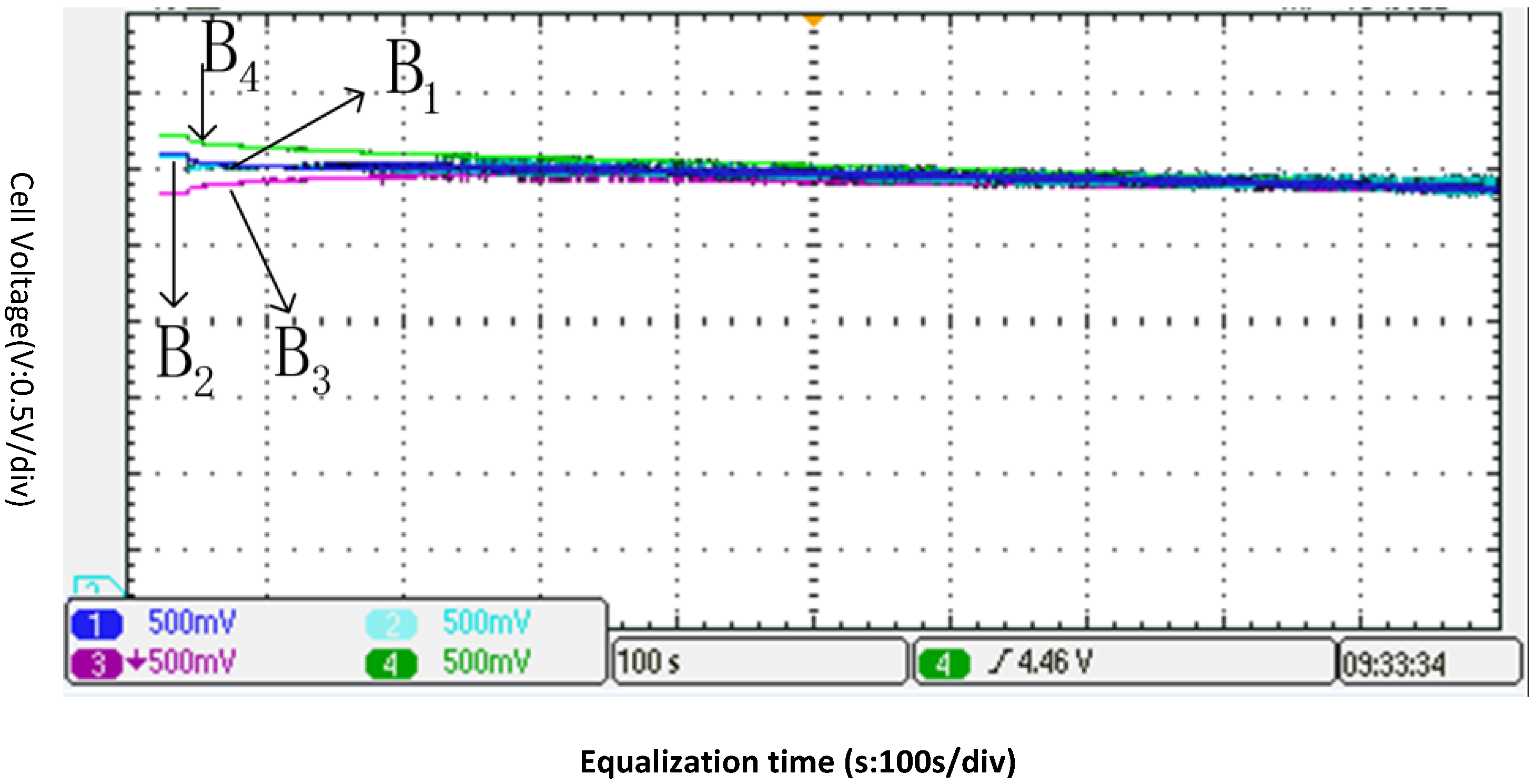
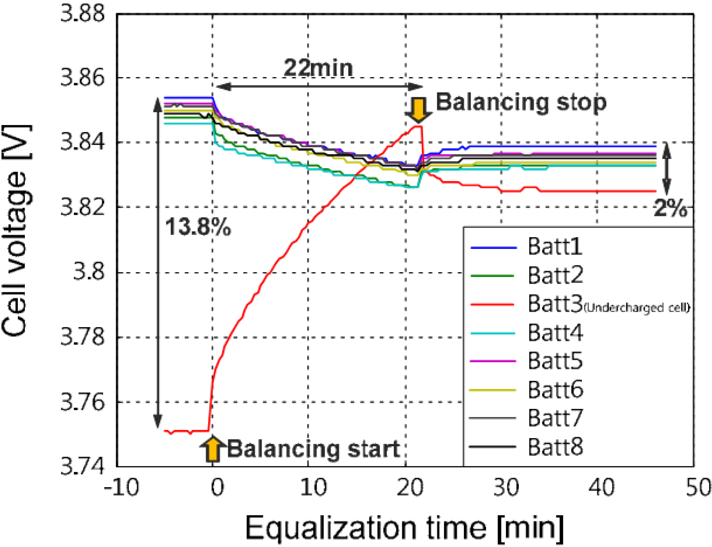
5. Experiment Result

In order to verify the control strategy based on dynamic balanced point, a prototype of four battery cells is implemented. To show the equalization performance of the prototype, an equalization test is conducted. Figure 15 shows the experimental wave forms. Battery voltages before and after charge equalization is shown in Table 2.
Figure 15. Experimental wave forms about DC-DC converter.
Energies 08 01830 g015
Table 2. Battery voltages before and after charge equalization.
BatteryInitial Voltage (V)Final Voltage (V)
B 1 3.112.90
B 2 3.092.90
B 3 2.852.89
B 4 3.212.90
The highest voltage of four battery cells is 3.21 V ( B 4 ). The lowest voltage of four battery cells is 2.85 V ( B 3 ). After equalization for 960 s, the voltage gap is diminished from 0.36 V to 0.01 V. From Figure 15, it can be seen that the presented control strategy based on dynamic balanced point is feasible. The Figure 16 comes from [7] in order to make a comparison with this paper proposed method.
Figure 16. Experimental wave forms about multi-output converter.
Energies 08 01830 g016
From Figure 16, it can be seen that the highest voltage of four battery cells is 3.854 V ( B 1 ). The lowest voltage of four battery cells is 3.750 V ( B 3 ). The voltage gap is diminished from 0.104 to 0.014 V after 22 min. Compared with Figure 16, any cell in the proposed method will only release charges or receive charges, this balancing method of tracing the dynamic balanced point will reduce the energy circulating from one cell to the other cell. Thus, this control strategy can reduce switching losses and accelerate the process of balancing. For this reason, the equalization time in Figure 15 is less than that in Figure 16. Therefore, the proposed balancing method is expected to be suitable for the series connected battery strings on speed. Due to the experimental conditions and time, our balance efficiency is slightly lower, which we need to improve in the future.

6. Conclusions

Cell equalization is no doubt an important issue that has to be considered in the application of lithium-ion battery strings. Especially for EVs, a mass of cells should be connected serially in order to supply enough energy, while the inconsistency problem between cells leads to poor performance. Employing a good equalizer and design a right control strategy is necessary as to avoid the shortage.
The applied balancing structure can drive high currents with less loss and the purposed control strategy has the ability to successfully improve the performance of the equalizer. Cell voltages have been limited in a small difference after equalization during both charging and discharging process.

Acknowledgments

This work was supported by the National Natural Science Foundation of China (Grant No. 51367006).

Author Contributions

All authors contributed to equal parts to the paper. Dong-Hua Zhang and Guo-Rong Zhu designed and conceived the article. Shao-Jia He and Shi Qiu performed the experiments. Yan Ma performed the simulation. Qin-Mu Wu and Wei Chen given some constructive suggestions. All the authors read and approve the manuscript.

Conflicts of Interest

The authors declare no conflict of interest.

References

  1. Hatzell, K.B.; Sharma, A.; Fathy, H.K. A survey of long-term health modeling, estimation, and control of lithium-ion batteries: Challenges and opportunities. In Proceedings of the IEEE American Control Conference, Montreal, QC, Canada, 27–29 June 2012; pp. 584–591.
  2. Shafiei, A.; Williamson, S.S. Plug-in hybrid electric vehicle charging: Current issues and future challenges. In Proceedings of the IEEE Vehicle Power and Propulsion Conference, Lille, France, 1–3 September 2010; pp. 1–8.
  3. Cassani, P.A.; Williamson, S.S. Significance of battery cell equalization and monitoring for practical commercialization of plug-in hybrid electric vehicles. In Proceedings of the IEEE Applied Power Electronics Conference and Exposition, Washington, DC, USA, 15–19 February 2009; pp. 456–471.
  4. Lindemark, B. Individual cell voltage equalizers (ICE) for reliable battery performance. In Proceedings of the 13th Annual International Telecommunications Energy Conference, Kyoto, Japan, 5–8 November 1991; pp. 196–201.
  5. Moo, C.S.; Hsieh, Y.C.; Tsai, I.S. Charge equalization for series-connected batteries. IEEE Trans. Aerosp. Electron. Syst. 2003, 4, 704–710. [Google Scholar] [CrossRef]
  6. Kimball, J.W.; Krein, P.T. Analysis and design of switched capacitor converters. In Proceedings of the 20th Annual IEEE Applied Power Electronics Conference and Exposition, Austin, TX, USA, 6–10 March 2005; Volume 3, pp. 1473–1477.
  7. Hopkins, D.C.; Mosling, C.R.; Huang, S.T. The use of equalizing converters for serial charging of long battery strings. In Proceedings of the 6th Annual Applied Power Electronics Conference and Exposition, Dallas, TX, USA, 10–15 March 1991; pp. 493–498.
  8. Moore, S.W.; Schneider, P.J. A review of cell equalization methods for lithium ion and lithium polymer battery systems. In Proceedings of the SAE 2001 World Congress, Detrolt, MI, USA, 5–8 March 2001.
  9. Kim, M.-Y.; Kim, C.-H.; Cho, S.-Y.; Moon, G.-W. A cell selective charge equalizer using multi-output converter with auxiliary transformer. In Proceedings of the 2011 IEEE 8th International Conference on Power Electronics and ECCE Asia (ICPE & ECCE 2011), Jeju, Korea, 30 May–3 June 2011; pp. 310–317.
  10. Ji, X.; Cui, N.; Shang, Y.; Zhang, C.; Sun, B. Modularized charge equalizer using multiwinding transformers for Lithium-ion battery system. In Proceedings of the 2014 IEEE Conference Transportation Electrification Asia-Pacific (ITEC Asia-Pacific), Beijing, China, 31 August–3 September 2014; pp. 1–5.
  11. Gerislioglu, B.; Ozturk, F.; Sanli, A.E.; Gunlu, G. The multi-windings forward structure battery balancing. In Proceedings of the 2014 11th International Conference Electronics, Computer and Computation (ICECCO), Abuja, Nigeria, 29 September–1 October 2014; pp. 1–4.
  12. Park, K.B.; Kim, H.S.; Moon, G.W. Single-magnetic cell-to-cell charge equalization converter with reduced number of transformer windings. IEEE Trans. Power Electron. 2012, 27, 2900–2911. [Google Scholar] [CrossRef]
  13. Baronti, F.; Fantechi, G.; Roncella, R. High-efficiency digitally controlled charge equalizer for series-connected cells based on switching converter and super-capacitor. IEEE Trans. Ind. Inform. 2013, 9, 1139–1147. [Google Scholar] [CrossRef]
  14. Kim, M.-Y.; Kim, J.-H.; Moon, G.-W. Center-cell concentration structure of a cell-to-cell balancing circuit with a reduced number of switches. IEEE Trans. Power Electron. 2014, 29, 5285–5297. [Google Scholar] [CrossRef]
  15. Chen, M.; Zhang, Z.; Feng, Z.; Chen, J.; Qian, Z. An improved control strategy for the charge equalization of lithium ion battery. In Proceedings of the Twenty-Fourth Annual IEEE Applied Power Electronics Conference and Exposition, APEC 2009, Washington, DC, USA, 15–19 February 2009; pp. 186–189.
  16. Qi, J.; Lu, D.D.-C. Review of battery cell balancing techniques. In Proceedings of the Power Engineering Conference (AUPEC), 2014 Australasian Universities, Perth, Australia, 28 September–1 October 2014; pp. 1–6.
  17. Moo, C.-S.; Wu, T.-H.; Hou, C.-H.; Hsieh, Y.-C. Balanced discharging of power bank with buck-boost battery power modules. In Proceedings of the 2014 International Power Electronics Conference (IPEC-Hiroshima 2014—ECCE-ASIA), Hiroshima, Japan, 18–21 May 2014; pp. 1796–1800.
  18. Cadar, D.; Petreus, D.; Patarau, T.; Etz, R. Fuzzy controlled energy converter equalizer for lithium ion battery packs. In Proceedings of the International Conference on Power Engineering, Energy and Electrical Drives, Malaga, Spain, 11–13 May 2011; pp. 1–6.
  19. Zhou, C.Y.; Xu, J.P. Research on Battery Charge Equalization System Based on FPGA/NIOSS II. Master’s Thesis, Southwest Jiaotong University, Chengdu, China, May 2008. [Google Scholar]
  20. Cassani, P.A.; Williamson, S.S. Design, testing, and validation of a simplified control scheme for a novel plug-in hybrid electric vehicle battery cell equalizer. IEEE Trans. Ind. Electron. 2010, 57, 3956–3962. [Google Scholar] [CrossRef]
  21. Ling, R.; Dong, Y.; Yan, H.B.; Wu, M.R.; Chai, Y. Fuzzy-PI control battery equalization for series connected lithium-ion battery strings. In Proceedings of the 7th International Power Electronics and Motion Control Conference, Harbin, China, 2–5 June 2012; Volume 4, pp. 2631–2635.
  22. Amjadi, Z.; Williamson, S.S. Novel control strategy design for multiple hybrid electric vehicle energy storage systems. In Proceedings of the 24th Annual IEEE Applied Power Electronics Conference and Exposition, Washington, DC, USA, 15–19 February 2009; pp. 597–602.
  23. Cao, J.; Schofield, N.; Emadi, A. Battery balancing methods: A comprehensive review. In Proceedings of the IEEE Vehicle Power and Propulsion Conference, Harbin, China, 3–5 September 2008; pp. 1–6.
  24. Erickson, R.W.; Maksimovic, D. Fundamentals of Power Electronics, 2nd ed.; University of Colorado Boulder: Boulder, CO, USA, 2001. [Google Scholar]

