1. Introduction
One of the important recent milestones in the machining field has been the development of advanced precision machining processes. Chief among them, precision turning is an efficient process for machining precise cylindrical components with tight tolerances and high quality features, which has increased its deployment for industrial applications [
1]. Precision hard turning refers to the use of a single point tool to machine materials that have high strength, corrosive resistance, toughness, ductility, and wear resistance [
2]. These are referred to as ‘hard-to-cut’ materials, e.g., nickel superalloys, titanium alloys, and stainless steel [
3,
4]. Precision hard turning is considered a profitable and dependable alternative to grinding, with a reduction in machining time as high as 60% [
5]. It is worth emphasizing that appropriate cutting conditions have to apply to enable precision hard turning to deliver very fine machined surfaces [
6,
7,
8].
Precision hard turning is used in numerous applications, including bearings, dies, gears, and molds because it improves the quality of the product while simultaneously reducing lead times and manufacturing costs [
9]. These benefits are especially noticeable with, for example ceramics, polycrystalline cubic boron nitride (PcBN) and tungsten carbide tools which are commercially available as super-hard tool materials. Different approaches, entailing experimental [
1,
3,
4,
5,
6,
7,
9,
10,
11,
12,
13], analytical [
14,
15], and FEM [
16,
17,
18,
19,
20,
21,
22,
23,
24,
25,
26,
27,
28,
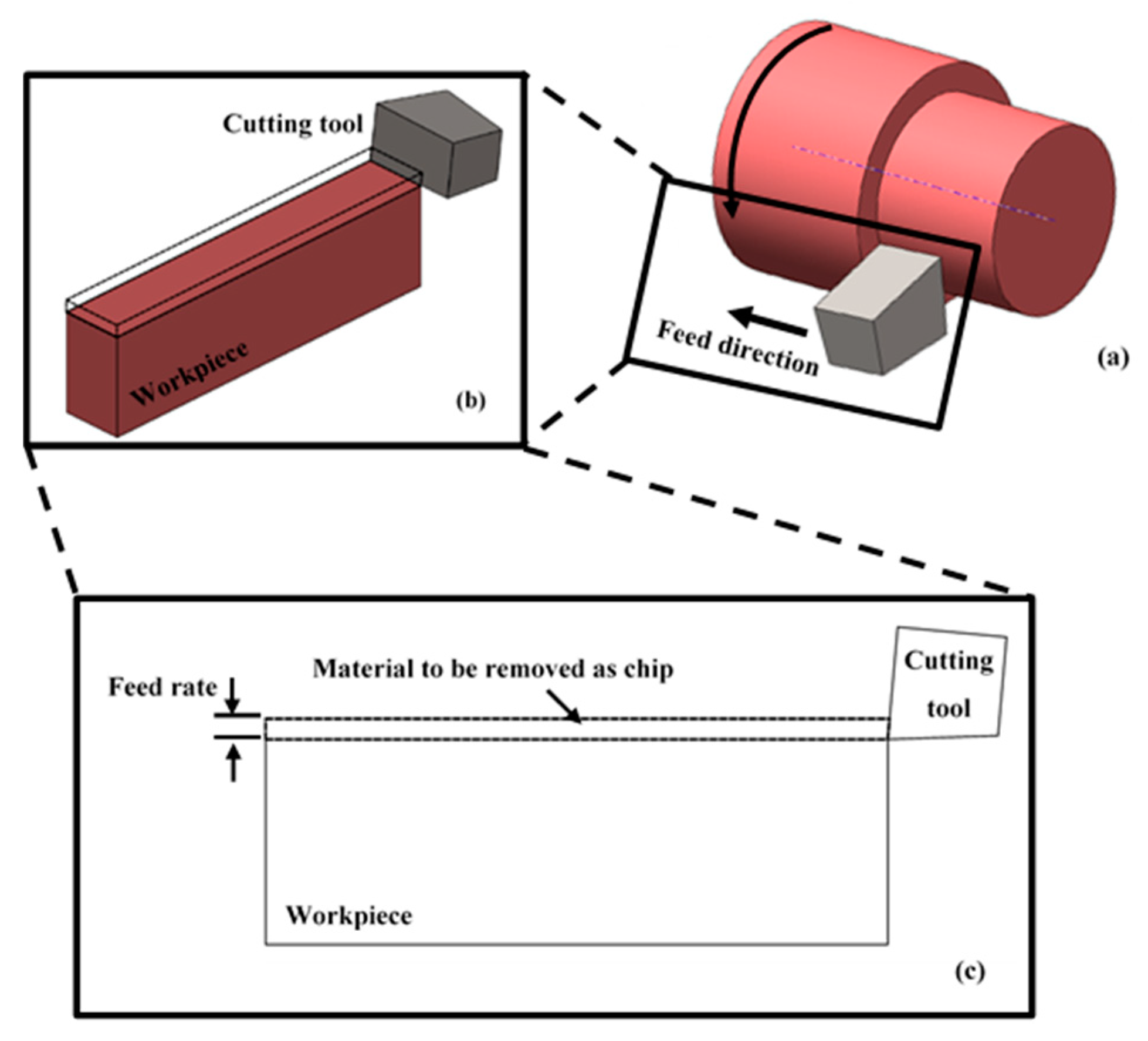
29], have been utilized to examine the performance of a wide range of machining operations in terms of surface quality, generated cutting force and tool wear. Nevertheless, the potential of the precision hard turning process has not been fully realized as of yet. This is caused because of the constraints of size-scale of the process. As in precision hard turning, the cutting edge radius of the tool and the feed rate are comparable in scale. Therefore, there can be substantial differences between the physical principles that govern the underlying phenomenon of this technique at the macro scale. Resulting in undesirable changes to the chip formation and surface generation processes [
10,
11]. In particular, in contrast to conventional turning where the obtainable surface roughness decreases proportionally with the reduction of undeformed chip thickness (applied feed), in precision hard turning the undeformed chip thickness can be smaller than the cutting edge radius of the tool [
12,
16]. When the undeformed chip thickness is less than the minimum chip thickness, a certain thickness of the material to be removed under which no cutting mechanism occurs, ploughing is the governing mechanism. This is associated with generation of rough surface. In addition, the ploughed material ahead of the tool cutting edge exerts high stresses on the cutting tool which accelerates tool wear and results in even higher surface roughness [
12,
17].
A number of researchers have performed FEM simulation of machining processes validated by experimental tests, with the aim of determining the optimum parameters for a given process [
18].
Shao et al., [
19] investigated tool wear and cutting temperature for the turning of Ti-6Al-4V alloy with a Tungsten carbide–cobalt cutting tool. Combining FEM with thermo-dynamics, a comparison was undertaken between experimental results and simulation predictions for depth of tool wear with cutting temperature. The accuracy of the FEM was confirmed by good match of practical results and FEM model simulations, but only on condition that the parameters input for cutting tool and workpiece were correctly chosen.
Akbar et al., [
20] examined the performance of the machining process in terms of the heat generated and its division between the chip and the cutting tool. The investigation was carried out by FEM modelling and, then, was validated by experiments with infrared techniques used to measure the cutting temperature. It was reported that the heat generated could significantly alter the contact area between tool and chip, and therefore affect the ability of FEM model to simulate the process. Accurate measurement of the heat division between chip and tool was necessary for accurate FEM modelling of the cutting operation.
Zhou et al., [
21] used a polycrystalline diamond (PCD) tool to carry out 2-D orthogonal cutting of SiCp/Al composites. The study investigated von-Mises equivalent stresses and the cutting force under different cutting conditions both experimentally and with a FEM model. Simulation and experimental results agreed that the machining of SiCp/Al composites needs to be at as high cutting speed as possible. However, they found that the inverse applied to cutting depth. They also found that the removal of SiCp particles was dependent on the relative position of cutting tool and particle.
Li, [
22] used FEM simulations to simulate the progression of tool wear in turning operation under conditions where cutting process variables were difficult to obtain experimentally.
Yang et al., [
23] used FEM to investigate the mechanical behavior of hydrogenated-6Al-4V alloy at high strain rates and elevated temperatures using a split Hopkinson pressure bar. The cutting process was modelled numerically, and the results obtained showed that an increase in hydrogen content significantly affected the temperature and cutting forces. Further investigation by simulation showed that it was better to machine titanium hydride at high cutting speeds.
John et al., [
24] investigated surface roughness of AISI 1020 steel when cut at different speeds with different feed rates and depths of cut using HSS tools and CNMA diamond inserts. This study used both FEM simulation and experimental tests. The differences between the experimental results and simulation results ranged between 3.74% and 22.8% for the HSS tool and between 1.15% and 11.8% for the CNMA insert. The best surface quality for the AISI 1020 steel using the CNMA insert tool was obtained at: cutting speed of 5.45 mm/sec, depth of cut of 0.50 mm and feed rate of 0.05 mm/rev. However, the quality of the surface obtained using diamond insert was better than that obtained using the HSS tool.
Haddag et al., [
25] reported a two-step modelling strategy to investigate cutting tool heat transfer. The initial step was to simulate chip formation and estimate the cutting forces via a 3-D thermo-mechanical FEM model. The final step was to simulate the thermal response of the cutting tool under thermal load using a 3-D FEM thermal model. This thermal load was estimated using quantities gained during the initial step; including sliding velocity, and contact area and pressure. Comparison between model and experimental results were in good agreement.
Ali et al., [
26] compared the results obtained from an FEM model with experimental results when studying the machining of Ti-6Al-4V. However, the simulation and experimental results showed a significant difference.
Bushlya et al., [
27] developed an FEM model to simulate the creation of machined subsurface layer when turning using a tool with a nose-radius and compared the simulation results with experimental measurements. The simulation predicted multiple deformations of the workpiece material would take place in the region around the tip of any tool with a nose radius. Numerous distortions of the machined surface were observed when machining at low feed rates using tools with a sizeable nose radius. These results suggested that the formation of the machined surface was, in significant part, due to severe wear of the cutting tool which was the result of work-hardening of the surface material.
Aurich et al., [
28] developed an FEM model to analyze the accuracy of turning operations using dry machining and compared the simulated results with experiments. It was shown that the cutting operation had a substantial effect on the heat generated which then affected the cutting tool, tool holder and workpiece, and thus could detract from the accuracy of the process. It was claimed that least depth of cut, maximum cutting speed, and feed rate, gave maximum accuracy of machining. These authors found that the temperatures of both tool holder and tool must be considered to ensure maximum accuracy of machining.
Maruda et al., [
30] utilized FEM to study chip formation and tool wear of sintered carbide P25 tool when turning AISI 1045 steel under different cooling methods, i.e., dry machining, MQCL method and MQCL + EP/AW, under a range of cutting speeds. The results revealed that MQCL method with phosphate ester-based additive reducing the friction coefficient between the chips and rake face of the tool which and chip thickening coefficient which eases the chip removal away from the cutting zone.
From the literature it is clear that there has been a noticeable number of studies of precision hard turning. Nevertheless, there is still a need for a deeper understanding of the science behind the underpinning chip formation and surface generation of the precision hard turning process at micro scale. This is because the large body of the reported work has, generally, examined the process responses at conventional ranges of the process parameters (viz. when the values of the applied feed rate are well above the value of the cutting edge radius of the tool at which the underlying mechanism is mainly pure cutting) [
1,
4,
7,
31,
32,
33,
34]. However, at micro-scale machining, to achieve a proper chipping mechanism and high-quality machined surface and minimum cutting forces, extremely restrictive cutting conditions, especially the applied feed, have to be identified and rigorously applied. Accordingly, the current research focusses on filling the gaps in the current scientific understanding of precision hard turning to examine the influence of the restricted cutting conditions (particularly applied feed rate at the vicinity of the edge radius of the cutting tool, due to their significant influence on the process performance). However, powerful engineering tools such as FEM are needed to better understand the process in its details. In this regard, the aim for this manuscript is to carry out a FEM-based study to examine the influence of a limited range process conditions (under which the cutting mechanism changes dramatically) on the chip formation and surface generation process when machining stainless steel 316L workpieces in a precision hard turning operation. The results of the FEM will be used to identify the optimum cutting parameters that enable proper chipping mechanism, higher quality of the machined surface and increased productivity of the process.
Following to this introduction, the remainder of this paper is organized as follows. Firstly, the FEM simulation procedure is described. Then, the experimental set-up is detailed, including a description of workpiece material, machine setup, applied cutting conditions and instrumentation. After that, the paper discusses the FEM obtained results, the agreement between these results and experiments. Next, the effect of the applied feed rate on surface quality is analyzed. Finally, the paper summarizes and draws relevant conclusions based on the results and discussion.
5. Conclusions
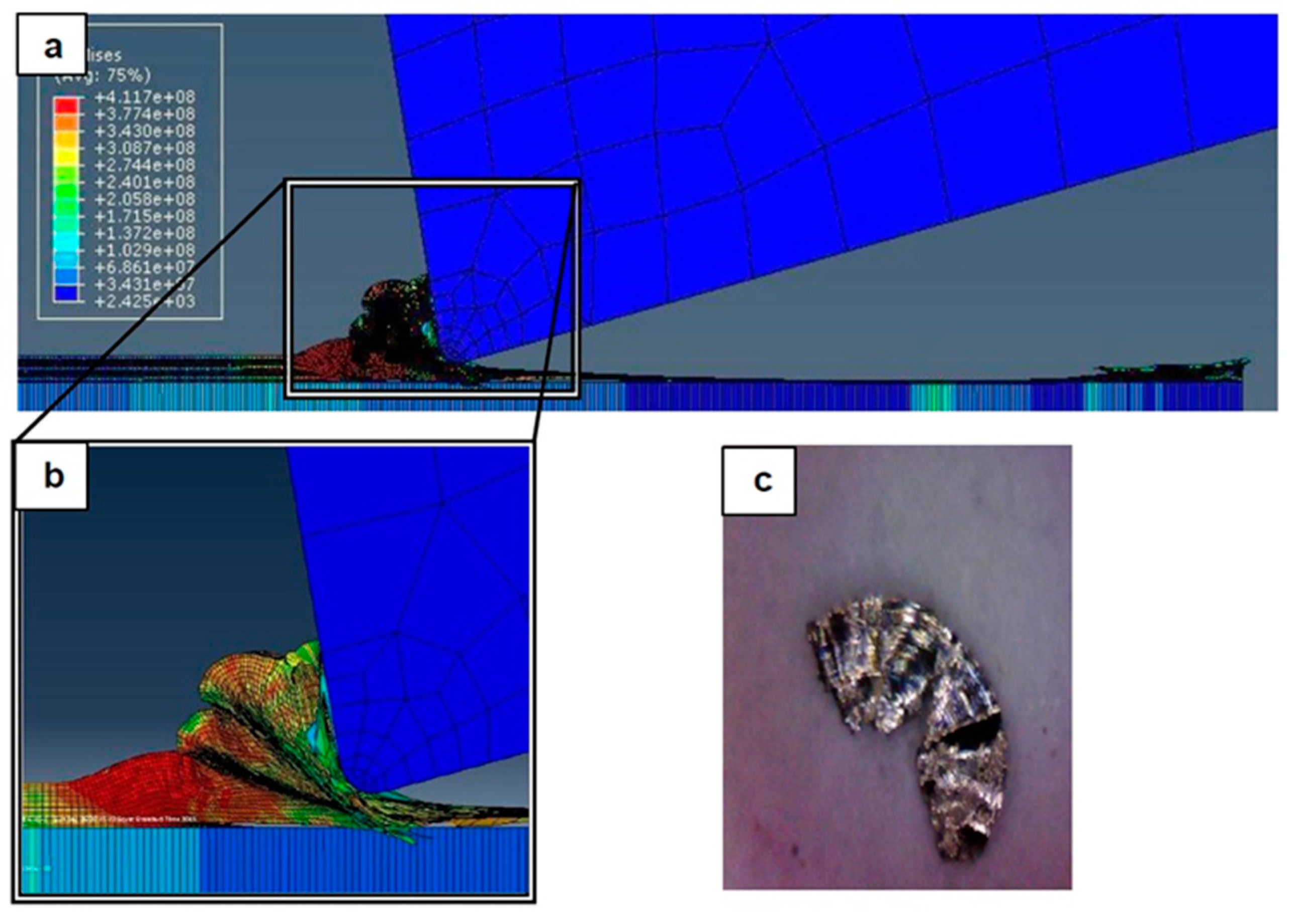
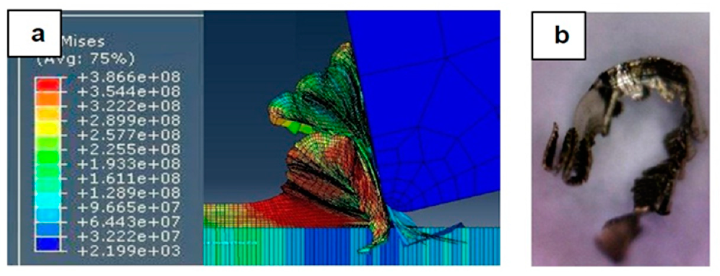
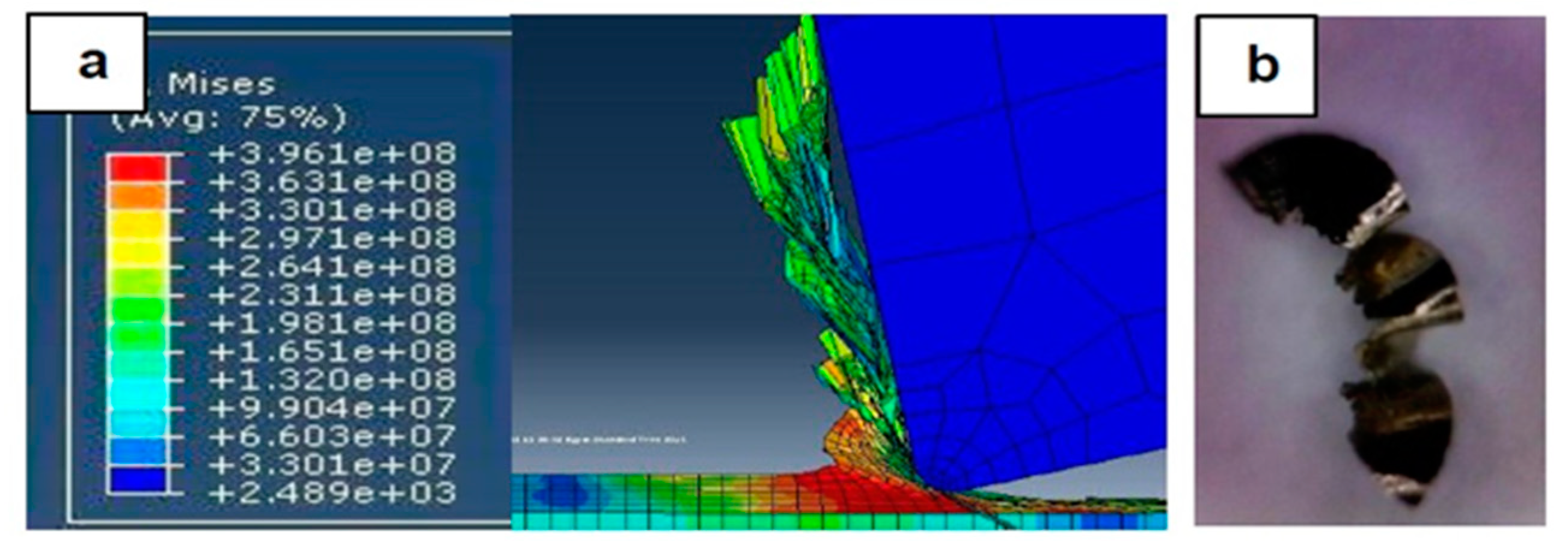
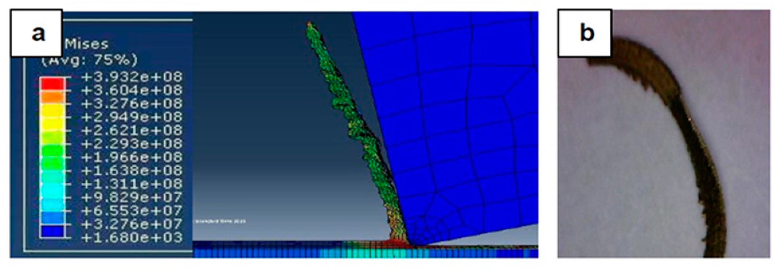
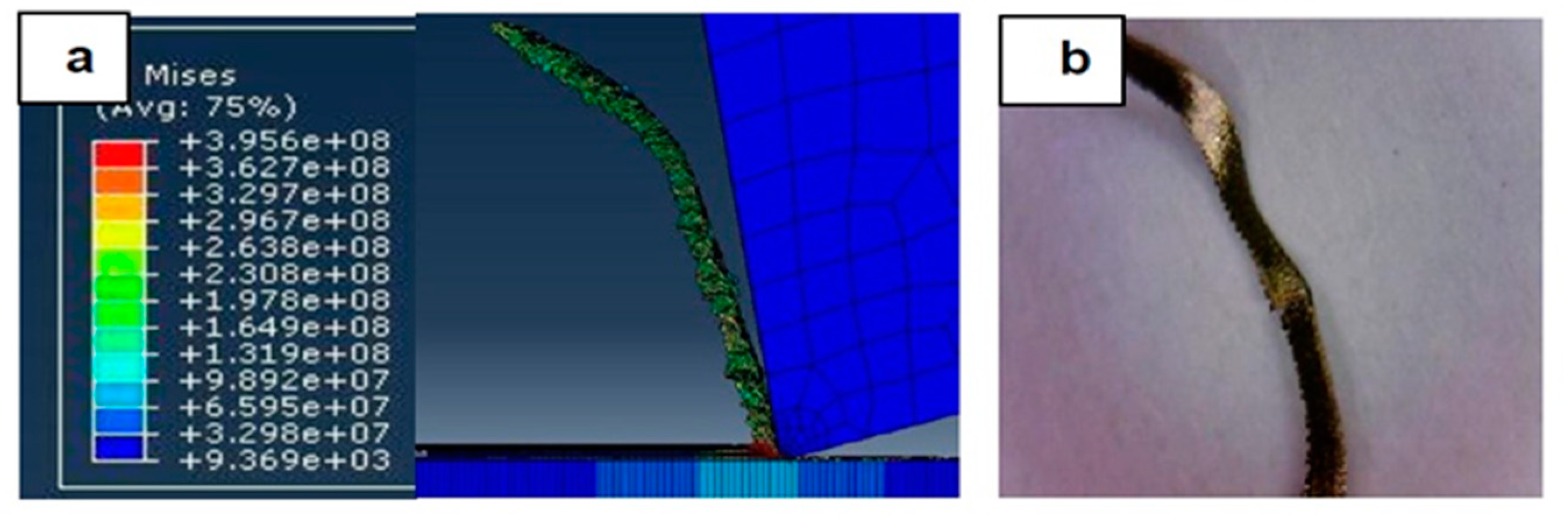
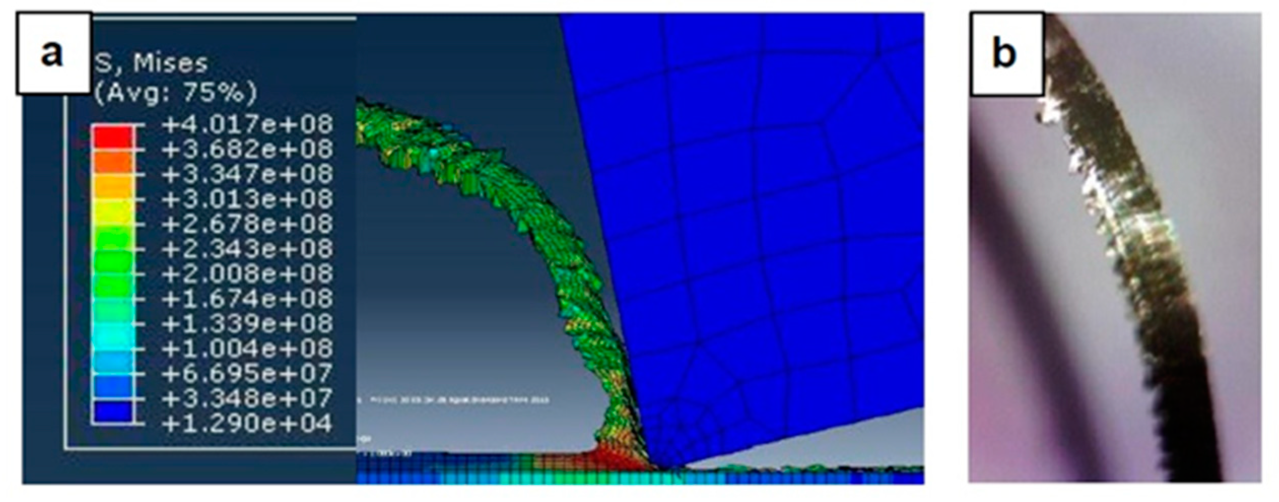
This article has reported the results of a FEM modelling and simulation study of chip formation and surface generation during the turning of stainless steel 316L. These simulation results were then compared with those obtained by experimental trials in order to establish the feasibility of this approach. Seven sets of experimental tests were performed on a CNC turning machine and the morphologies of the formed chips were employed as the performance indicator and criteria for comparison of the FEM simulations and experimental findings. In addition, the surface roughness was experimentally evaluated twice for each machining trial, first after tuning the first path (with a new tool) and second after finishing the turning operation (where the tool considered worn) to identify the relationship between feed rate and surface roughness for new and worn tools. The main conclusions drawn are as follows:
The results reveal that a strong relationship exists between the applied feed rate, the cutting tool edge radius and the governing cutting mechanism. The chip formation process is controlled by this strong relationship. Particularly, the transition between mixed cutting/ploughing process into a complete cutting mechanism was observed when the feed rate exceeded the minimum chip thickness, meaning that the optimal cutting conditions of stainless steel 316L are at 75% of the cutting tool edge radius. Especially, when the applied feed was just greater than the value of the minimum chip thickness, the cutting mechanism altered from mixed cutting/ploughing to pure cutting with conventional chip formation. This is considered the optimal cutting parameters, when the minimum surface roughness was generated and when lowest stresses were observed.
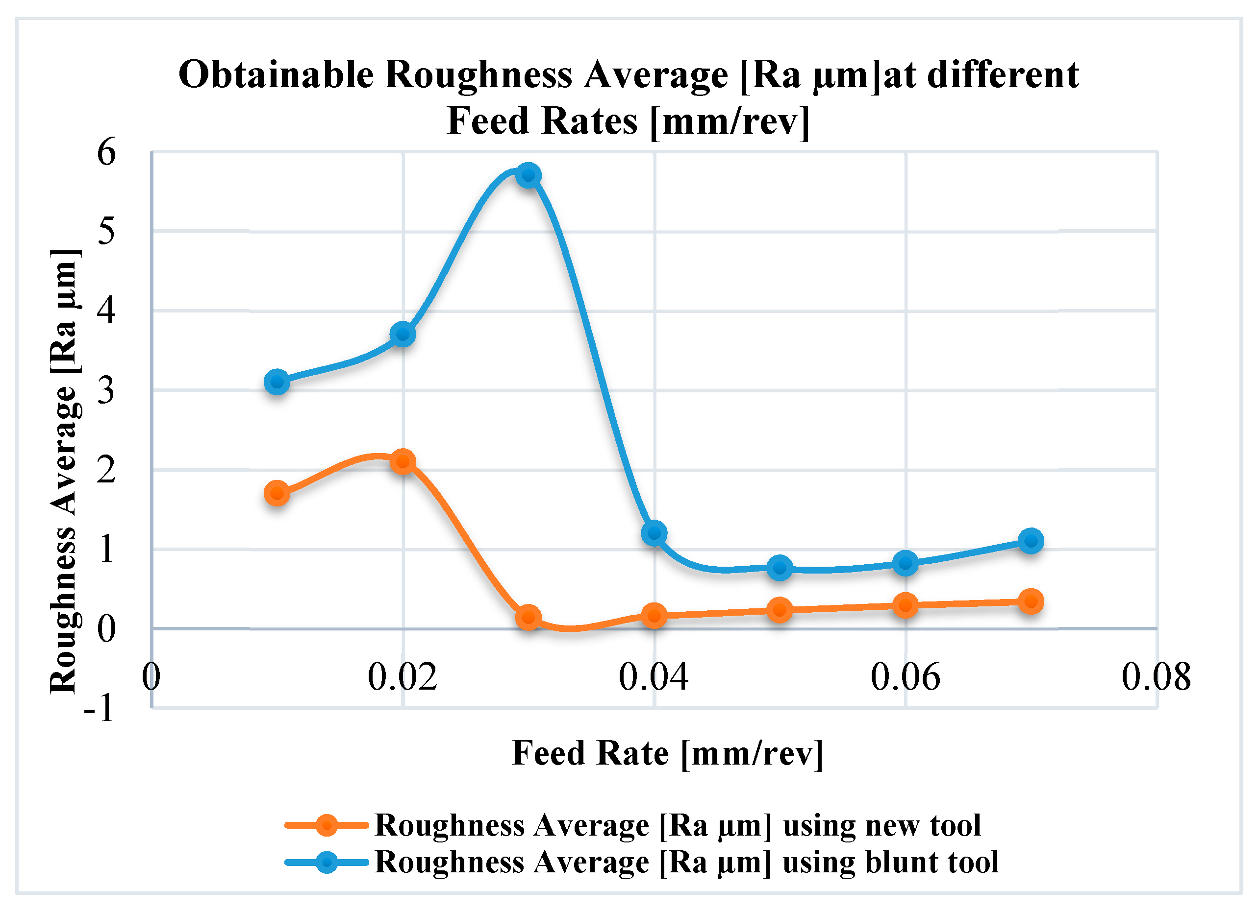
Surface roughness was affected by feed rate in a non-linear manner. Minimum surface roughness occurs when the feed rate lies between about 0.75 to 1.25 times the original edge radius of the cutting tool. From this it is concluded that the edge radius also has an effect on surface roughness in a way that is related to feed rate. There was a major peak in the surface roughness measurements as the feed rates decreased below 0.03 mm/rev for the new tool and 0.04 mm/rev for the worn tool. This can be explained by minimum chip thickness effects. However, further reduction in the feed rate led to improvements in the surface finish which could be attributed to changes in the cutting mechanisms, from cutting to burnishing.
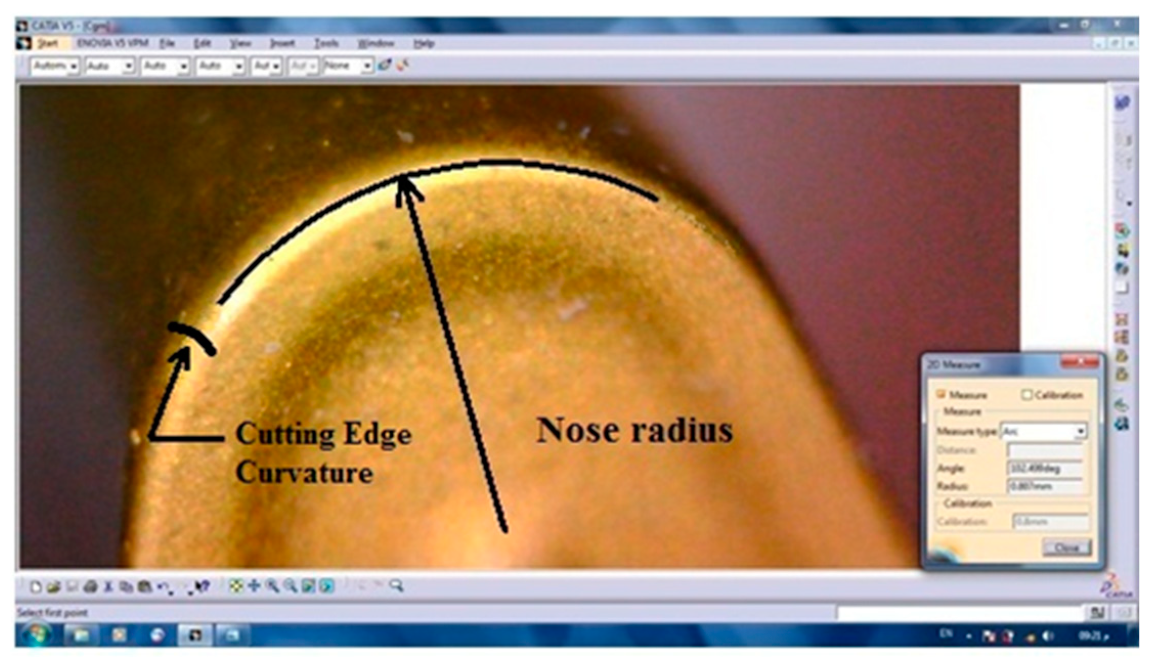
This investigation revealed the importance of the insert edge radius, re. The value of the cutting edge radius of the tool played an important role in the cutting process, determining the optimum feed rate to produce minimum surface roughness and optimize tool wear. Thus, re should be known before selecting a cutting insert, especially for fine turning operations where accurate dimensions and best surface finish are essential.
It is worth reiterating that this study focused on limited process parameters due to their significant influence on the process outcomes. However, in future work investigation of further process parameters such as cutting speed and type of cooling and their effects on other process responses such as cutting forces, tool wear and surface integrity will be conducted.


