1. Introduction
Magnetic field sensors are widely used in various fields, for example, in the industry, agriculture, medicine, aerospace, marine, exploration, and drilling. In recent years, the magnetoelectric (ME) composites with a product property of magnetostrictive and piezoelectric phases have been of great importance for the realization of a magnetic sensor [
1,
2,
3]. In the ME effect, an electric field is induced under the application of a magnetic field or conversely, magnetization is induced under the application of an external electric field [
1,
2,
3]. To date, different magnetic sensors based on ME composites have been experimentally and theoretically investigated in order to obtain the best ME coupling through changing the structures [
4,
5,
6,
7], materials [
8,
9,
10], number of layers [
11,
12], etc.
Among the proposed composites, the 2-2 laminated composite material has a good ME coupling effect at room temperature, a large degree of freedom in design, and a strong application prospect, which provides a clear physical meaning for the design of a new generation of electronic devices [
1,
2,
3,
4,
5,
6,
7,
8,
9,
10,
11,
12]. Recently, for static or quasi-static magnetic field sensing in an unshielded room temperature and pressure and lab environment, a high direct current (DC) magnetic field sensitivity of 2.8 Hz/nT and a limit of detection of 800 pT were reported in the NEMS AlN/FeGaB resonator [
13]. For alternating current (AC) magnetic field sensing, an extremely low equivalent magnetic noise of 5.1 pT/√Hz at 1 Hz was reported in the Metglas/piezofiber structure [
14]. A super-high magnetic sensitivity of 1.35 × 10
−13 T was directly detected at 23.23 kHz in the 1D (1-1) connectivity ME composites of Metglas/PMN-PT [
15].
In practice, transient pulsed magnetic field measurement exists in many fields, such as lightning current in power systems [
16,
17] and aircrafts [
18,
19], crack detection with pulsed magnetic flux leakage techniques [
20,
21], and transient electromagnetic measurement in transformer substations [
22]. However, to date, most of the reported theoretical and experimental studies carried out on ME sensors have been investigated under the premise of static magnetic field and standard sine wave magnetic field excitation [
1,
2,
3,
4,
5,
6,
7,
8,
9,
10,
11,
12,
13,
14,
15]. Only a few studies have focused on the transient response of ME materials in pulsed magnetic fields [
23]. The magnetic–mechanical–electric nonlinear coupling mechanism of the magnetostrictive/piezoelectric structure should be different by changing the parameters of transient magnetic fields. Thus, for potential applications in pulsed magnetic field measurement of the ME composite, this paper focused on the transient nonlinear ME response under a pulsed magnetic field. The influence of the pulsed magnetic field parameters and external bias field on the ME structure were investigated in detail.
2. Experimental
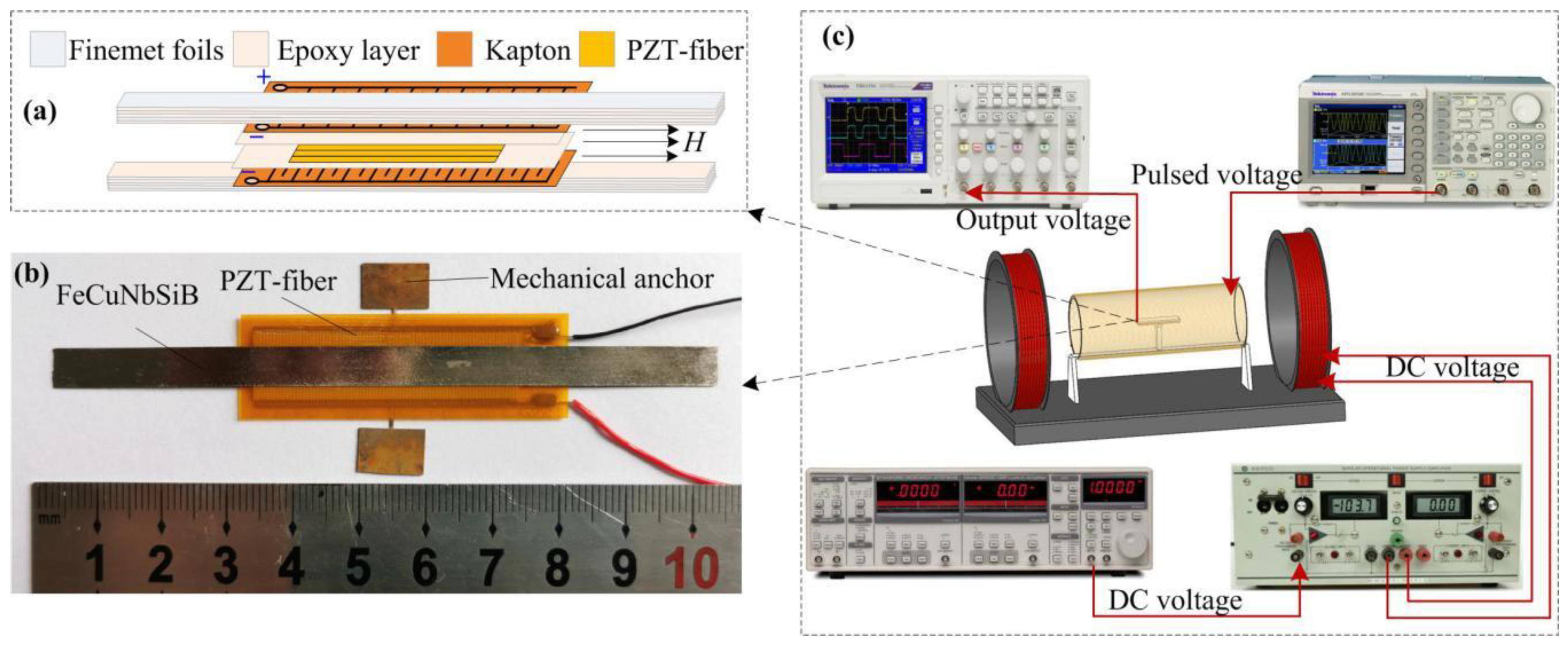
The ME structure consists of Fe
73.5Cu
1Nb
3Si
13.5B
9 (FeCuNbSiB) and piezofiber, as shown in
Figure 1a,b. The FeCuNbSiB (International standard trademark 1K107, produced by Foshan Huaxin Microlite Metal Co., Ltd., Foshan, China) is a pizeomagnetic phase with a high permeability (μr = 30,000), high saturation magnetization (μ
0Ms = 1.45 T), and a large anisotropic constant (−30,000 J/m
3). The dimensions of the FeCuNbSiB foils are 10 × 6 × 0.025 mm
3. The Pb(Zr, Ti)O
3 fiber composite (piezofiber) (M4010-P1, provided by Smart Material Cor., Sarasota, FL, U.S.A.) is a piezoelectric phase consisting of rectangular piezoceramic rods (40 mm long and 180 μm thick) sandwiched between layers of adhesive, electrodes, and polyimide film. The electrodes are attached to the film in an interdigitated pattern which transfers the applied voltage directly to and from the ribbon-shaped rods.
As shown in
Figure 1a, two FeCuNbSiB layers (each made by three FeCuNbSiB foils) were subsequently laminated to both the top and bottom surfaces of the Pb(Zr, Ti)O
3 (PZT)-fiber layer. Under an AC magnetic field, a mechanical strain was generated in the FeCuNbSiB layer and was then transferred to the piezofiber, resulting in the generation of charges due to the direct piezoelectric effect. As shown in
Figure 1b, the ME FeCuNbSiB/piezofiber was designed to operate as a half-wavelength longitudinal resonator vibrating freely at both ends. Thus, one mechanical anchor (made by Beryllium bronze plate, produced by Shanghai Dayu Metal Products Co., Ltd., Shanghai, China) bonded with epoxy at the middle of the FeCuNbSiB/piezofiber where the displacement was zero.
The experimental setup is shown in
Figure 1c. A signal generator (Tektronix AFG3021B, Tektronix Inc., Beaverton, OR, USA) provided a controllable input current to a long straight solenoid coil with 1800 turns and a 182 mm length, which was used to provide the pulsed magnetic field. A Helmholtz coil (Linkphysics Co., Ltd., Shanghai, China) was used to provide the DC bias magnetic field, which was driven by a power amplifier (KEPCO Bipolar Operational Power Supply, KEPCO Inc., Flushing, NY, USA.). The ME output voltages of the FeCuNbSiB/piezofiber laminate were measured with a lock-in amplifier (SR-830, SRS, Sunnyvale, CA, USA.) and an oscilloscope (Tektronix Inc., Beaverton, OR, USA). The bias magnetic field H
bias was measured with a Gauss meter. The AC magnetic field was calculated in the experiments. The resistance of the long straight solenoid coil was measured as 37.8 Ω by a multimeter (Fluke Corporation, Everett, WA, USA). In addition, the voltage of the long straight solenoid in the experiments was measured by an oscilloscope. Thus, the actual current
I in the long straight solenoid can be calculated as I = voltage/37.8. Then, the AC magnetic field of the central solenoid H = n*I (A/m), where n = 1800/0.182. Before the experiments, the calculated AC magnetic field was calibrated by a Fluxgate probe (CH-Magnetoelectricity Technology, Beijing, China).
3. Results and Discussion
The ME response of the FeCuNbSiB/piezofiber composite was calibration-tested under a standard sine magnetic field.
Figure 2a shows the ME coefficient α
ME and the phase angle as a function of the bias magnetic field H
bias driven at a 1 kHz sine magnetic field. As shown in
Figure 2a, α
ME increased with increasing H
bias up to about H
bias = 3.6 Oe reached a maximum value of α
ME = 9.2 mV/Oe and then gradually decreased as H
bias was further increased. The induced voltage was independent of H
bias history and no offset value was found near H
bias = 0 Oe. These characteristics are quite important to magnetic field detection. In addition, as the direction of H
bias was changed, a 180° phase shift was found, as shown in
Figure 2a. Next, α
ME was measured as a function of the AC magnetic field frequency at H
bias = 5.2 Oe while sweeping near the mechanical resonance, as shown in
Figure 2b. As this figure shows, the fundamental resonant frequency for the FeCuNbSiB/piezofiber composite was ~26.47 kHz. At this resonant frequency, a value of α
ME > 50 mV/Oe was reached. The natural period of the FeCuNbSiB/piezofiber composite
T = 1/
fr = ~37.78 μs.
For the ME composite consisting of mechanically coupled magnetostrictive and piezoelectric layers, the resonance frequency of the ME composite is [
12]
where
l is the length, and
and
are the average density and the equivalent elastic compliance, respectively. The length of the PZT-fiber is 40 mm. The
and
of PZT-fiber is 5.44 g/cm
3 and 32.96 × 10
−12 m
2/N, respectively. The length of the FeCuNbSiB foils is 100 mm. The
and
of FeCuNbSiB is 7.25 g/cm
3 and 5.2 × 10
−12 m
2/N, respectively. The calculated first-order longitudinal resonant frequencies of the PZT-fiber and the FeCuNbSiB foil are ~29.5 kHz and ~25.8 kHz, respectively. Thus, the resonant frequency for the FeCuNbSiB/PZT-fiber stack should be about ~25.8 kHz to ~29.5 kHz. In order to calculate the resonance frequency of FeCuNbSiB/piezofiber, we used the ANSYS 19.0 software (ANSYS, Inc., Canonsburg, PA, USA). In the simulations, the elastic modulus and density of the epoxy layer were 3 GPa and 5 g/cm
3, respectively. The simulation results of the first-order longitudinal vibration are shown in the inset of
Figure 2b. The first-order longitudinal resonant frequency of the FeCuNbSiB/PZT-fiber was ~28.14 kHz. The theory calculated and the simulation results agree with the experimental results.
Then, the transient nonlinear ME coupling was investigated in detail.
Figure 3 shows the time dependence output voltage
Vo of the FeCuNbSiB/piezofiber structure driven by the magnetic field pulse with a width (Δt) of ~100 μs and an amplitude of 51 Oe. The inset of
Figure 3 shows the detail when times were 0–200 μs. The rise time of the pulse magnetic was ~8.4 ns. From this figure, the
Vo increased gradually when the pulsed magnetic field increased rapidly to an amplitude of 51 Oe and maintained ~100 μs. This is because the magnetic energy increased gradually when the pulsed field maintained the amplitude. It is clear that
Vo oscillated at the period Δt
1 = ~37.78 μs. After t > Δt = 100 μs, the pulse magnetic field decreased rapidly to zero. However, the
Vo decreased gradually and oscillated at the period Δt
2 = ~37.78 μs. This is due to the inertia effect of the FeCuNbSiB/piezofiber structure. The FeCuNbSiB/piezofiber ME structure is a mechanical resonant structure that self-vibrates near the equilibrium position at the natural period
T when the pulsed magnetic field vanishes. It is clear that the FeCuNbSiB/piezofiber structure always oscillates at the natural period
T in the time domain. If the width of the pulsed magnetic field Δt is equal to
T or multiples of
T, what will happen?
Figure 4 shows the time dependence
Vo of the FeCuNbSiB/piezofiber structure driven by magnetic field pulses with amplitudes of 51 Oe and widths of Δt = T–5T. The inset of
Figure 4 shows the detail when times were 0–250 μs. After t >Δt, it is interesting that the self-vibration phenomena vanished when Δt = T–5T, which is extremely different from
Figure 3. This result can be explained by the fact that the FeCuNbSiB/piezofiber structure was exactly in an equilibrium position when the pulse magnetic field vanished. Moreover, the other interesting result from
Figure 4 is that
Vo grew exponentially, which was excited by the same amplitude pulsed magnetic field of 51 Oe when Δt = T–5T. This result demonstrates that the ME FeCuNbSiB/piezofiber structure can be used as a pulse magnetic width measured device, and this will be investigated in detail in the following section.
Based on
Figure 2a, the ME response of the FeCuNbSiB/piezofiber structure is dependent on the H
bias. Therefore, the H
bias dependence of the ME response for the FeCuNbSiB/piezofiber structure driven by the pulsed magnetic field was also investigated.
Figure 5 shows the peak output voltage V
p (maximum
Vo in
Figure 3) as a function of H
bias for the FeCuNbSiB/piezofiber structure driven by the pulsed magnetic field with Δt = ~100 μs. The curve tendency in this figure is the same as that in
Figure 2a. The maximum V
p was ~0.9 V at H
bias = 3.6 Oe.
Next, the transient sensing characteristics of the FeCuNbSiB/piezofiber structure was investigated. Firstly, the amplitude of the pulsed magnetic field H
A sensitivity was measured. Consequently,
Figure 6 shows the peak output voltage (like the peak in
Figure 3) as a function of H
A at H
bias = 0 Oe. The different values of amplitude of the pulsed magnetic field H
A were obtained at Δt = ~100 μs. The linear fitting expression based on the experimental data was
Vp = 0.017
HA–0.0433. Based on
Figure 6, it is obvious that the induced ME voltage had a near linear (R
2 = 0.9675) relation with H
A. The observation indicates an improved detection sensitivity of 17 mV/Oe. Clearly, the presented FeCuNbSiB/piezofiber sensor seems to be an ideal application for the detection of amplitude variations of pulsed magnetic fields.
From
Figure 4, changing Δt results in the variation of the output voltage of the FeCuNbSiB/piezofiber structure.
Figure 7 shows the peak output voltage (like the peak in
Figure 3) as a function of the width of the pulsed magnetic field Δt = 0–500 μs as H
bias = 0 Oe. It is evident that the
Vp increases with Δt and reaches its maximum value after Δt >300 μs. For the linear fitting at Δt = 0–300 μs, the relationship between
Vp and Δt is
Vp = 0.0054Δt + 0.212. One can see that the linear (R
2 = 0.9757) dependence of the V
p on the Δt takes place in a region of 0 < Δt < 300 μs. Based on the slope of the plots, the sensitivity of the FeCuNbSiB/piezofiber structure for pulsed width sensing was determined to be 5.4 mV/μs. It can be concluded that this ME sensor is suitable for pulsed width measurement fields, such as lightning current monitoring.
