2.1. Material
Powder (Carpenter Additive, Widness, UK) used for the production of all samples was gas atomized steel 316L (1.4404) in an argon atmosphere. Powder particles had spherical shapes of 15–63 µm in diameter. The density of the material was 7.92 g/cm
3, and its flowability was 14.6 s/50 g. The material chemical composition based on the quality check of the powder obtained from the supplier is shown in
Table 1.
To verify powder particles’ chemical composition additional analysis has been performed using an electron backscatter diffraction (EDS) module on a scanning electron microscope (SEM, Jeol JSM-6610, Jeol Ltd, Tokyo, Japan). Recorded data is shown in
Table 2.
The lack of other elements (Mn, P, S, and N) in the analyzed chemical composition is connected with a very low amount of the mentioned elements at the registered measurement points.
2.2. Manufacturing Process
The 3D models of testing samples were designed by SolidWorks 2019, based on the ASTM E466 96 standard, and were then used in the manufacturing process for an SLM 125HL device (SLM Solutions AG, Lubeck, Germany). All performed investigations including microstructure, residual stress, and hardness analyses were performed on the same samples to obtain reliable results.
Our tests [
32] indicated that the microhardness and porosity values changed by 10% percent after modification of selected process parameters. The mentioned parameter modifications included laser power, laser exposure velocity, and hatching distance (a gap between exposure lines). The main reason for specific parameter selection was their significant influence on energy density during the manufacturing process. In accordance with Equation (1), the energy density depends on four different parameters:
where
LP—laser power [W],
ev—exposure velocity [mm/s],
hd—hatching distance [mm] and
lt—layer thickness [mm].
The parameters selected for modification were affected by the device’s optical system and laser source. Layer thickness, which was not included in the research, is controlled by the worm geared mechanical system which is less precise than the galvanometric system for optic steering. The second reason for layer thickness elimination for further analysis was the lack of ability to change this parameter during a single process for each manufactured specimen. From a group of preliminarily determined parameters [
32], the following three were chosen which were most significant groups (parameters are specified in
Table 3):
- “S_01”—
the main SLM device fabrication parameters based on 316L steel.
- “S_17”—
group of parameters which were recorded when the highest porosity was observed during the manufacturing process with the lowest energy density from all groups. In addition, the lowest microhardness was observed in samples fabricated using this group of parameters.
- “S_30”—
group of parameters used to obtain the highest value of energy density based on a previous research [
22]. Parameter selection and their descriptions were based on our own preliminary research [
32,
33] to clarify the interpretation of research results.
Our approach allows understanding when a particular modification (process parameters, type of heat treatment) is effective for specific applications. We can also analyze the materials’ susceptibility to different types of heat treatment. Three selected groups of parameters were used for sample production to enable structural analysis including microstructure investigation and residual stress measurement; scleronomic hardness testing and tensile tests were performed by DIC based deformation analysis. The second stage of research involved obtaining parts of samples using two different types of heat treatment–precipitation heat treatment and hot isostatic pressing on samples fabricated with two parameters groups—“S_01” and “S_17”. After heat treatment, all types of early-made tests were carried out. The last part of the research included a combination of two types of heat treatment-precipitation heat treatment after hot isostatic pressing of “S_01” and “S_17” samples. The influence of precipitation heat treatment on the samples fabricated using “S_30” parameter group was also investigated. All samples from each series were manufactured during a single process to assure the same material properties of each sample from each group. The manufacturing processes of samples was carried out in an argon atmosphere with oxygen content lower than 0.2%. All samples were oriented horizontally. The orientation assures the highest possible strength and elongation of the additively manufactured parts [
34].
2.3. Research Methodology Description
The porosity and microstructure were analyzed using a LEXT OLS 4100 confocal microscope (Olympus Corporation, Tokyo, Japan). For preparation of samples for microstructural analysis, the samples were mounted in resin, ground with abrasive papers (grade: 80, 320, 600, 1500, and 2000), and polished using a 3-μm grade diamond paste. For porosity analysis the Mountains Map software (version 6.0) was used. Acetic glycergia was used as the etchant with a composition of 6 mL HCl, 4 mL HNO3, 4 mL CH3COOH and 0.2 mL glycerol. The etching time was 40 s.
Surface residual stresses in the two main, perpendicularly oriented directions (“σ1, σ2”) based on sin2ψ diffractometric measurements were obtained using a D8 Discover X-ray diffractometer (Bruker Corporation, Billerica, MA, USA) with an Euler wheel and a sample positioning system along the three axes. Test samples for the research were prepared using electrical discharge machining. Radiation and beam optics were characterized by CoKα filtration. Phase analysis was performed in the CrystalImpact Match! software (version 3.0) with an ICDD PDF 4+ 2019 crystallographic database. The residual stress analysis was based on Fe 111 and Fe 311 reflections of the austenitic phases of the samples. C11 = 204.0, C12 = 133.0, and C44 = 126.0 monocrystalline elastic constants were adopted for tested 316L steel.
Sclerometric hardness measurements were conducted on CETR‘s Universal Nano and Micro Tester (CETR INC, Campbell, CA, USA), and the width of average scratches was considered. The process of material scratching involved moving the indenter. The indenter was inserted in the sample with a constant, normally oriented load and an additional constant indenter movement speed. This method of measurement allowed structural analysis of the layered material, which is a characteristic of additively manufactured materials (the perpendicular surface to the machine’s building platform). The described surface is shown in
Figure 1. Sclerometric hardness was calculated using the exact differential method. For each sample, three scratches were made, and each scratch was measured three times, which is nine measurements for each sample.
Axial tensile strength tests of additively manufactured samples with structure analysis SLM of 316L steel were performed according to the ASTM E466 96 standard using a hydraulic pulsator (Instron 8802, Instron, Norwood, MA, USA). Measurements of the deformation under axial stretching were performed using an Instron 2630-112 extensometer with a measuring base of 25 mm. All samples subjected to axial tension exhibited the same geometry. Tensile tests were made accordingly to used standard in the research. Tests were run on five specimens for each configuration. For YS standard deviation was: +/− 6.1072 MPa, for UTS standard deviation was: +/− 6.1070 MPa. Sample surface deformation was analyzed during monotonic tensile tests performed using a digital image correlation (DIC) method. Deformations of the samples were observed using the Dantec Q-400 system (DANTEC DYNAMICS A/S, Skovlunde, Denmark) for three different specimen series (S_01, S_17, and S_30 before and after heat treatment) considering three characteristic parameters: yield strength, ultimate tensile strength, and breaking strength. The data received from the DIC system and tensile test machine were evaluated using ISTRA 4D software (version 4.4.1). The surface structures of the sample fractures after the tensile test were observed using a Jeol JSM-6610 SEM (JEOL Ltd, Tokyo, Japan).
Samples manufactured using the two groups of process parameters (S_01 and S_17) were obtained using hot isostatic pressing (HIP) in an argon atmosphere at 1150 °C under a pressure of 100 MPa for 3 h. The second type of heat treatment was precipitation heat treatment which was performed under an annealing temperature of 1060 °C for 6 h. To reduce the formation of high-dimensional grains, water cooling of the samples was performed directly after annealing. The second, equally important issue was to avoid the generation of the sigma phase in the material microstructure. Such precipitation is characterized by high hardness and brittleness, which negatively affect material properties.
2.6. Friction Force and Sclerometric Hardness Measurement
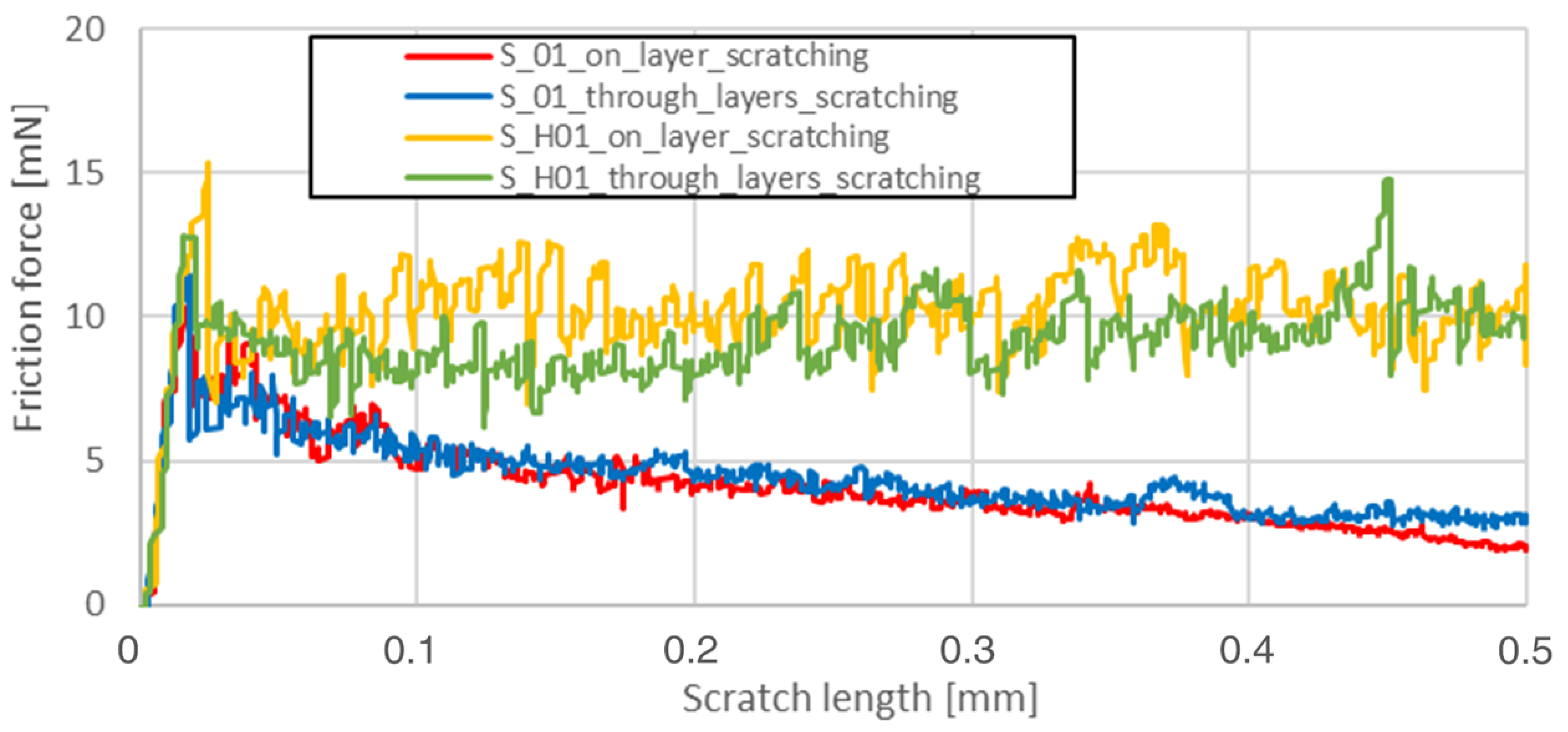
The friction force as a function of scratching length was analyzed on a surface parallel to the machine-building platform (XY plane). The main reason for data reduction was the lack of significant phenomena in the plane perpendicular to the machine’s building platform (YZ). Heat treatment completely reduced the visible influence of the layered structure in the YZ plane, which is shown in
Figure 3.
Friction force during scratching registered for S_01 sample made on the sample’s layer surface (red curve in
Figure 3) is characterized by a smaller friction force fluctuation than the blue one—made on this sample’s cross-section through layers surface. After HIP, no visible differences in both curves were observed. The results for the parallel plane of each sample are shown in
Table 5.
Based on the recorded scratching force, the scratch dimensions, and the equation associated with the indenter type, the sclerometric hardness of the specimens can be calculated using Equation (2):
where
HSp—sclerometric hardness (Pa),
F—normal force [N] and
w—average scratch width [m].
2.7. Tensile Strength and DIC Deformation Measurements
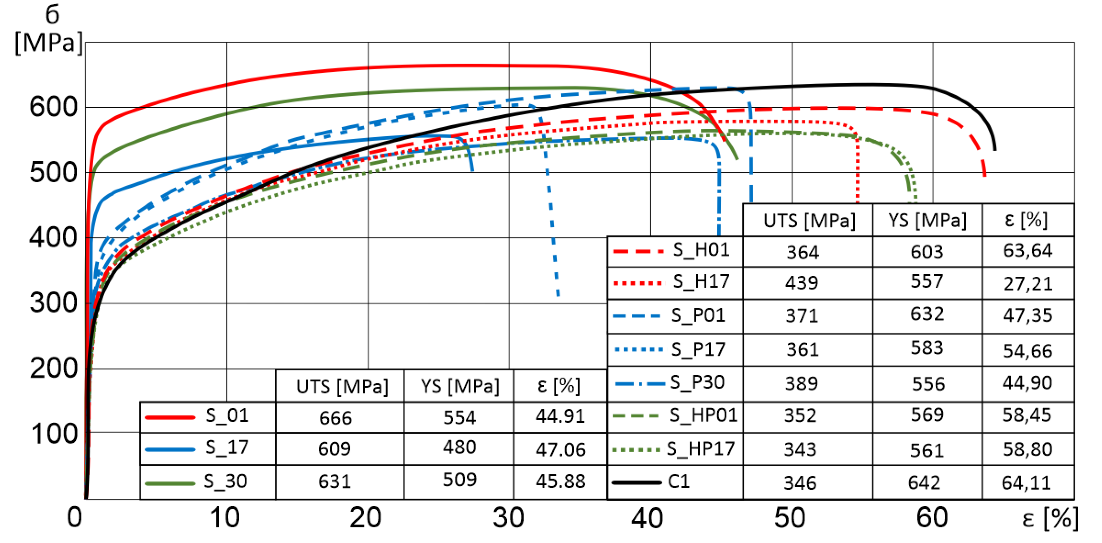
Tensile strength results of additively manufactured specimens subjected to additional heat treatment are shown in the chart (
Figure 4). The most significant growth in the tensile strength was recorded for sample S_HP17, which was subjected to two types of heat treatments. In all specimens subjected to precipitation annealing, we observed elongation and a decrease in the tensile strength. Furthermore, a conventionally manufactured sample (rolled metal sheet) was also considered (C1 in
Figure 4).
Selected laser melted parts have about 40% higher YS, about 4% higher UTS, and about 30% lower elongation at failure in comparison to conventionally manufactured samples. Additional heat treatment allowed to make materials properties closer to conventionally-made.
HIP and precipitation annealing of SLM-processed parts decrease YS and UTS strength properties with a simultaneous increase in elongation. This phenomenon is related to a significant modification of material structure, where there is a reduction of fine-grain after selective laser melting and heat treatment [
15].
Strain observations using the DIC system for three different specimen series (S_01, S_17, and S_30) considering three characteristic parameters—yield strength, ultimate tensile strength, and breaking strength—were additionally compared to heat-treated equivalent parts and conventionally fabricated samples. Deformation images are shown in
Figure 5.
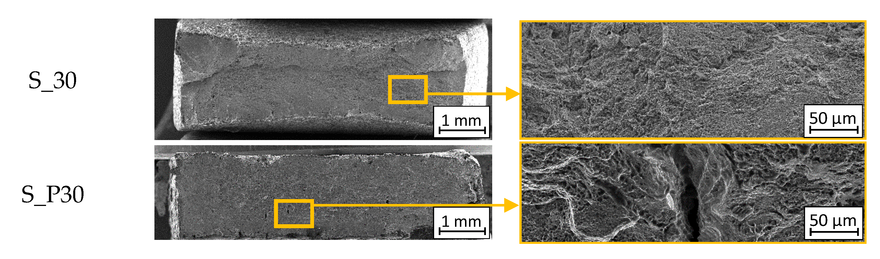
The results of our analysis showed that there was no evidence to demonstrate the nature of cracking during the tensile tests. The recorded SEM images, shown in
Figure 6, allow us to determine the cracking type of each sample.
Arrows mark the locations of occurrence of cracks near the pores of the material. The faults visible were caused by the inter-crystalline cracking process (
Figure 6).

 ,
, 


