1. Introduction
Recently, an approach to bone tissue regeneration based on cellularized-scaffold implantation was used to overcome the risks connected to bone grafts when self-healing fails [
1].
The focal point of scaffolds for bone tissue regeneration is unit cell topology which influences mechanical and biological performance [
1]. Suitable mechanical properties are required in load-bearing applications while suitable mass transport properties are necessary for biological activities [
2]. Both these features relate to porosity, pore size and pore interconnectivity, that in turn are determined by scaffold elementary unit cell geometry. Therefore, scaffold design must be balanced to allow nutrients and oxygen supply, metabolic waste removal, cell penetration and reduction of stress shielding to prevent mechanical failure [
3,
4].
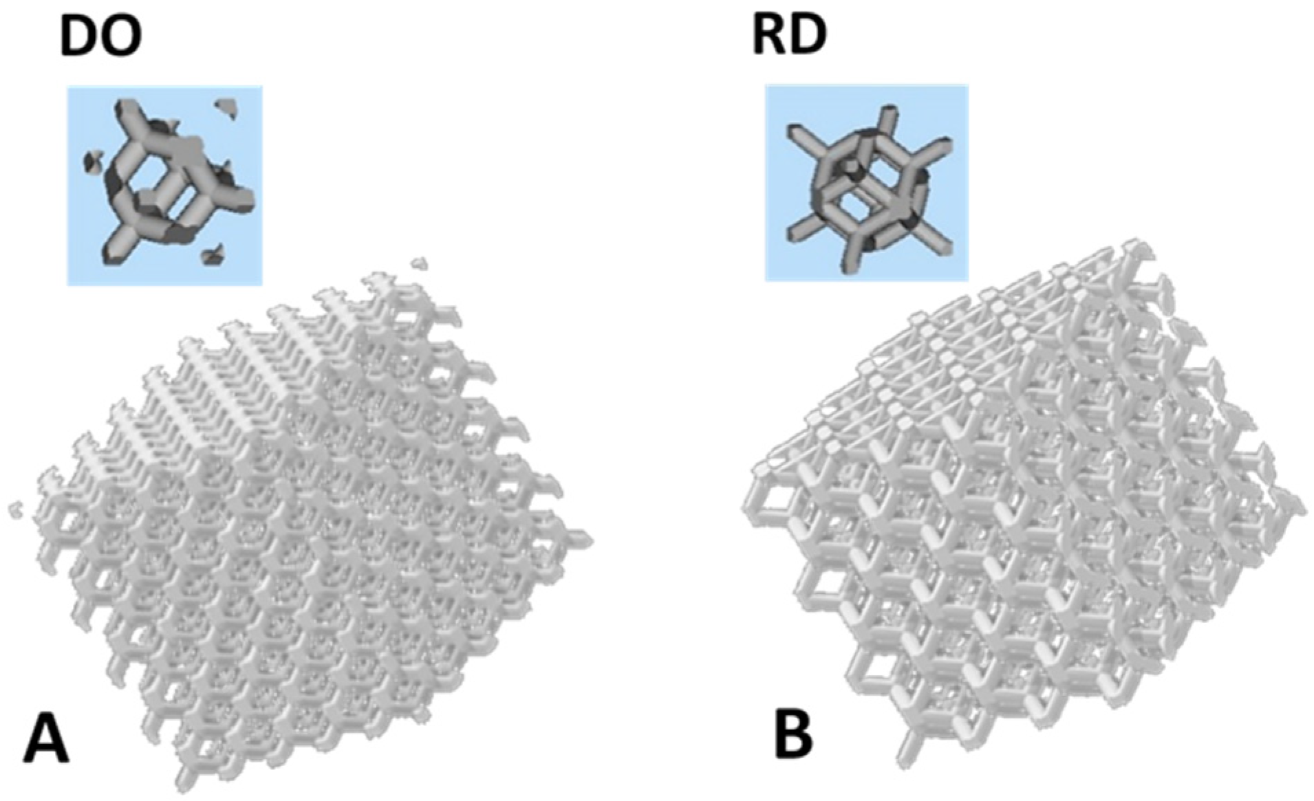
Two main elementary unit cell geometries for the scaffold are proposed in the literature: (a) diagonal symmetrical and (b) midline symmetrical. Finite element analysis (FEA) [
5] showed that a porous structure with midline symmetry exhibited superior compressive performances than diagonal symmetry, while the opposite trend was observed in the case of torsion. Therefore, rhombic dodecahedron (RD) unit cell geometry (midline symmetrical) is well suited for load-bearing implants, while diamond (DO) unit cell geometry (diagonal symmetrical) is preferable for implants subjected to torsional forces. In addition, numerical analysis by computational fluid dynamics (CFD) [
6] has demonstrated that DO shows advantages in implant fixation (greater tortuosity and larger aperture), cell growth environment (more appropriate adhesion areas), and tissue regeneration (due to regular mechanical stimulation), while RD shows a superior mass transport performance (higher flow velocity value). Therefore, DO and RD elementary unit cells are valid alternatives for bone tissue regeneration.
Accurate control of the anatomical shape, size and topology of the scaffold’s elementary unit cell can be efficiently obtained by additive manufacturing (AM) technology alternatives to traditional subtractive methods. Typically, AM processes for metal alloys consist of melting powders through an energy source (laser or electron beam) in a layer-by-layer process, according to a CAD file [
7,
8]. Laser-manufactured parts show lower surface roughness in comparison to electron beam melting (EBM) products, that generally exhibit residual stresses and gas contamination. Laser-melting technology is widely used for dental implants [
9,
10], while EBM is commonly employed in a patient’s customized bone implants [
11,
12].
Titanium alloys have an elastic modulus in the range 50–118 GPa, closer to natural cortical bone (10–30 GPa) than any other widely investigated alloy for permanent implant, such as cobalt chromium (240 GPa) and stainless steel (216 GPa) [
13]. However, the difference in elastic modulus between cortical bone and titanium alloys leads to stress shielding with reabsorption of the unstressed bone portion and consequent risk of implant failure [
14].
A combination of EBM technology and Ti6Al4V alloy has been investigated by Popov et al. [
11], that produced biomedical patient-specific implants for clavicle, mandibular bone, foot osteotomy and hip. In the reported clinical cases, EBM revealed a reduction of time in operation and patient recovery.
Despite the key advantages of combining EBM technology with Ti-based alloys, only a small percentage of tissue engineering research in this field achieves clinical application, due to the high cost of preclinical studies. To overcome this gap, Martinez−Marquez et al. [
15] proposed a step model to ensure the cost-effectiveness of customized scaffolds. In particular, they proposed material feedstock recycling as the first step in cost reduction. Material feedstock in EBM processes can affect up to 31% of the cost of built parts [
16]. Therefore, recycling Ti6Al4V metal powder represents an affordable solution to reduce waste and save costs [
17]. However, powder reuse means repeated preheating steps and prolonged thermal treatments in a vacuum during the EBM process that can induce changes in the reused powder, in terms of chemical composition, morphology and physical properties [
18]. In Ti6Al4V alloy thermal cycling due to powder reuse induces variations in particle size distribution and oxygen uptake that can lead it to exceed the O < 0.2 wt.% condition required by ASTM F2924-14 [
19]. Oxygen stabilizes the α-Ti phase which pins dislocation during part deformation. Thus, with powder reuse, ultimate yield strength slightly increases, while ductility decreases [
18,
20,
21].
In addition to elementary unit cell geometry and scaffold production technology, the engineering aspect to be improved for implant success is surface functionalization, which must fulfill scaffold–bone interface requirements. The most common functionalization treatment is coating the scaffold’s surface with a layer of biocompatible material or a combination of biocompatible compounds [
22,
23,
24]. Surface coating plays a double role: (a) avoids the release of toxic ions [
3,
4,
25,
26] and (b) improves implant osteointegration.
Currently, the researchers’ interest is focused on synthetic bioresorbable and biocompatible polymers such as polylactide (PLA), polycaprolactone (PCL) and polyglycolide (PGA) [
27]. Among them, PCL is the most promising due to slow degradation time (>24 months) with respect to PLA (12–16 months) and PGA (6–12 months) [
28]. However, to overcome the PCL drawbacks concerning structural (elevated hydrophobicity) and biological aspects (poor bioactivity and low cell adhesion), PCL is usually combined with ceramic materials such as hydroxyapatite (HA). HA shows excellent biocompatibility, bioactivity and osteoconductive properties, allowing enhanced bone formation and implant-site recovery [
29,
30].
In this paper, the elementary unit cell geometry, surface functionalization, mechanical properties and biological response of scaffolds based on Ti6Al4V alloy, produced with a mixture of reused and virgin new powders by the EBM technology, were considered for bone tissue regeneration. The aim of the work is to fabricate suitable scaffolds for in vivo perspectives starting from industrial EBM process based on cost and waste reduction in order to overcome issues connected to the high costs of preclinical studies. Starting from reused powder blended with virgin new powder as the raw material of the EBM process, scaffolds with DO and RD elementary unit cell geometry were produced. After production, scaffolds were submitted to topological and mechanical characterization to compare their performances with the experimental and simulated results reported in literature [
5] for identical structures (same alloy composition, production technology and elementary unit cell geometries). Afterwards, scaffolds were coated with a single layer of PCL or PCL/HA for surface functionalization and then submitted to biological tests. Human mesenchymal stem cell cultures for 24 h and 4 days were used as a fast check of the scaffold’s biological response. The role of unremoved residual powder in the scaffold core on mechanical and biological behavior was also considered. Results evidenced mechanical and biological performance of scaffolds produced by EBM industrial methods fully comparable to the literature data from scaffolds produced by virgin new powder, thus providing an indication for viable industrial processes for cost reduction of preclinical studies.
4. Discussion
The ideal scaffold for tissue regeneration must: (a) support the normal cellular activity without producing any harmful effect (biocompatibility), (b) allow cells to adhere, proliferate and form extracellular matrix on its pore and surface, (c) allow formation of blood vessels to support the transport of oxygen, nutrients and waste products. Therefore, obtaining an ideal scaffold means taking control of any aspect of the production chain starting from the selection of raw materials and production technology to the design of pore shape, size and interconnectivity. Furthermore, cell viability tests allow the checking of material biocompatibility and cell colonization of the produced scaffolds. Therefore, in the perspective of tissue regeneration, biological characterization is as essential as mechanical and structural characterization.
In this study, cell viability tests were used as a fast check of biological response concerning scaffold pore topology and surface functionalization coating. For this reason, viability tests were stopped after only 4 days of culture, even before stem cell differentiation.
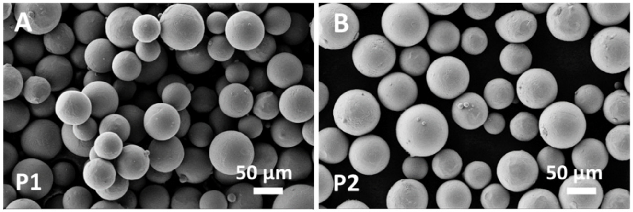
The raw material used to fabricate the scaffolds was Arcam Ti6Al4V powder blended in an unknown proportion with the same powder after several recycles. Blending recycled powder used in previous EBM processes with virgin new powder is common practice in the additive manufacturing industry to reduce costs and waste [
17]. Although the chemical composition (
Table 4) and lattice structure (
Figure 3) of the raw powder (P1) were almost unaltered with respect to the virgin new powder (P2), in agreement with Alamos et al. [
45], SEM images clearly showed particle aggregation through neck formation in P1 (
Figure 2A).
Powder sintering occurring during the preheating and melting steps of the EBM process led to the formation of necks between particles (
Figure 2A), that were responsible for powder aggregation. Although aggregation increased powder strength [
32], aggregated particles remained entrapped in the pores of scaffold core (
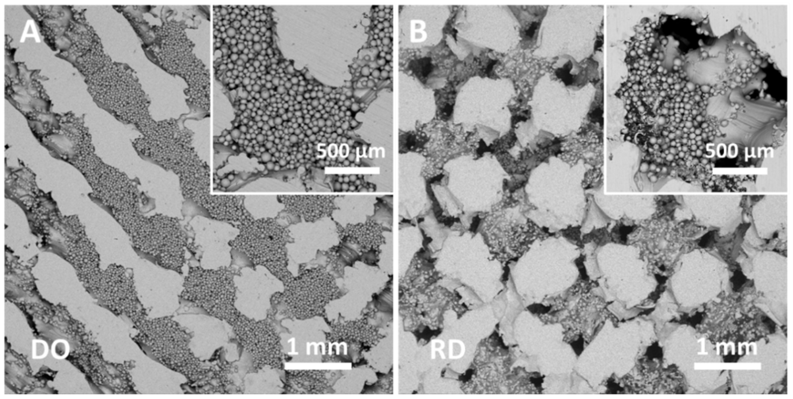
Figure 5) with consequences on scaffold topology-connected performance and mechanical properties.
The amount of residual powder inside the scaffold depended on geometry as evident in
Figure 5 and
Table 5. In particular, DO geometry, which had more intricate pore pathway for the release of unmelted powder entrapped inside the scaffold [
6], contained about 76% more residual powder than RD (
Table 5).
The most important geometrical features in DO and RD geometries such as pore size, strut size and porosity were investigated by Li et al. [
46] using software analysis. All these parameters not only affect biological performance but also play a central role in mechanical properties [
5].
Li et al. [
5,
46] investigated scaffold produced from virgin new powder with the same unit cell geometries (DO and RD) of our scaffolds that were produced with the blended P1 powder described above. Therefore, results obtained by Li et al. from software simulation [
46] and mechanical tests [
5] were taken here as reference and compared with our results in
Table 7.
In particular, Li et al. [
5] estimated a porosity value around 70% for both DO and RD unit cell geometry (
Table 7). In our case, the porosity experimental value was 63% for both geometries (
Table 7). Discrepancies between software calculated (
Table 2) and experimental values were fully due to the EBM manufacturing technique. In particular, the EBM processing parameters reported in
Table 3 allowed scaffold to be obtained with a strut size much larger (ranging from 800 to 1000 µm for both DO and RD geometries) than the nominal CAD values listed in
Table 2. This reduced scaffold porosity to 63% against the expected 80% of CAD calculation (
Table 2). Nevertheless, the struts were fully dense without pores or lack of fusion defects (
Figure 5).
The EBM process occurs in vacuum, thus avoiding any oxygen contamination that could modify the chemical composition and physical properties of the powder, even after reuse [
32]. However, the melting process in EBM can induce compositional variations in the final parts with respect to the metal powder. In our case, this event was confirmed by EDS analysis of scaffolds whose average chemical composition (
Table 6) showed slight decrease of vanadium with respect to the alloy’s nominal composition (
Table 1) and the experimental composition of the blended powder (
Table 4).
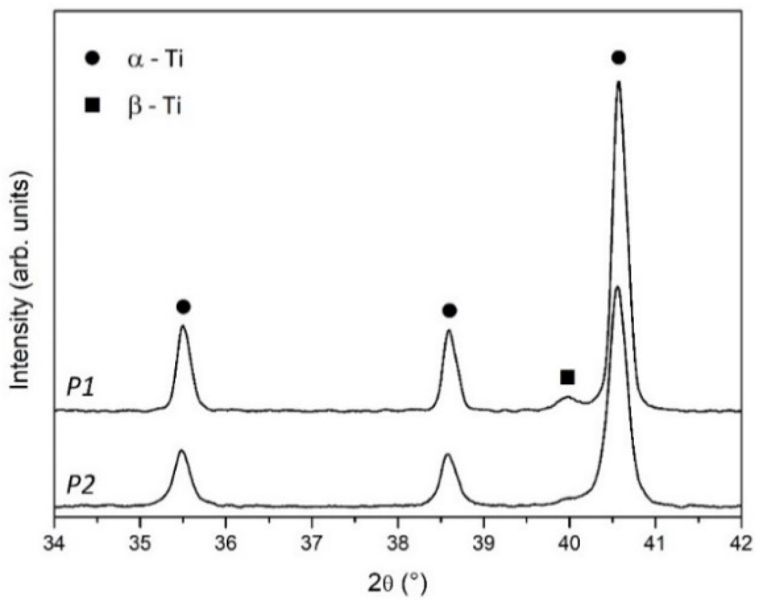
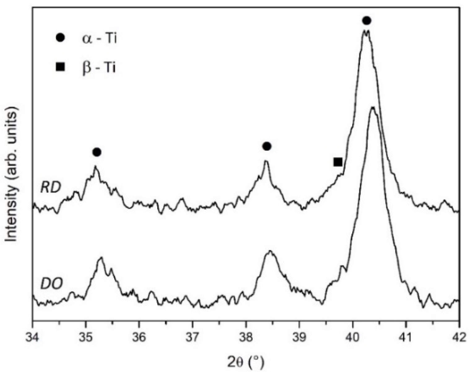
XRD analysis of P1 and P2 powders (
Figure 3) clearly showed the joint presence of α-Ti and β-Ti phases in both specimens. The peak intensity in the patterns evidenced better crystallization and higher β-Ti content in P1, due to the recycled part of blended raw powder. XRD patterns of scaffolds (
Figure 6) confirmed the joint presence of α-Ti and β-Ti phases suggesting that the vanadium decrease measured by EDS was incapable of deeply changing the alloy’s microstructure. Nevertheless, comparing the XRD patterns of powders (
Figure 3) and scaffolds (
Figure 6) a markedly reduced crystallinity and possible residual stresses in scaffolds could be argued.
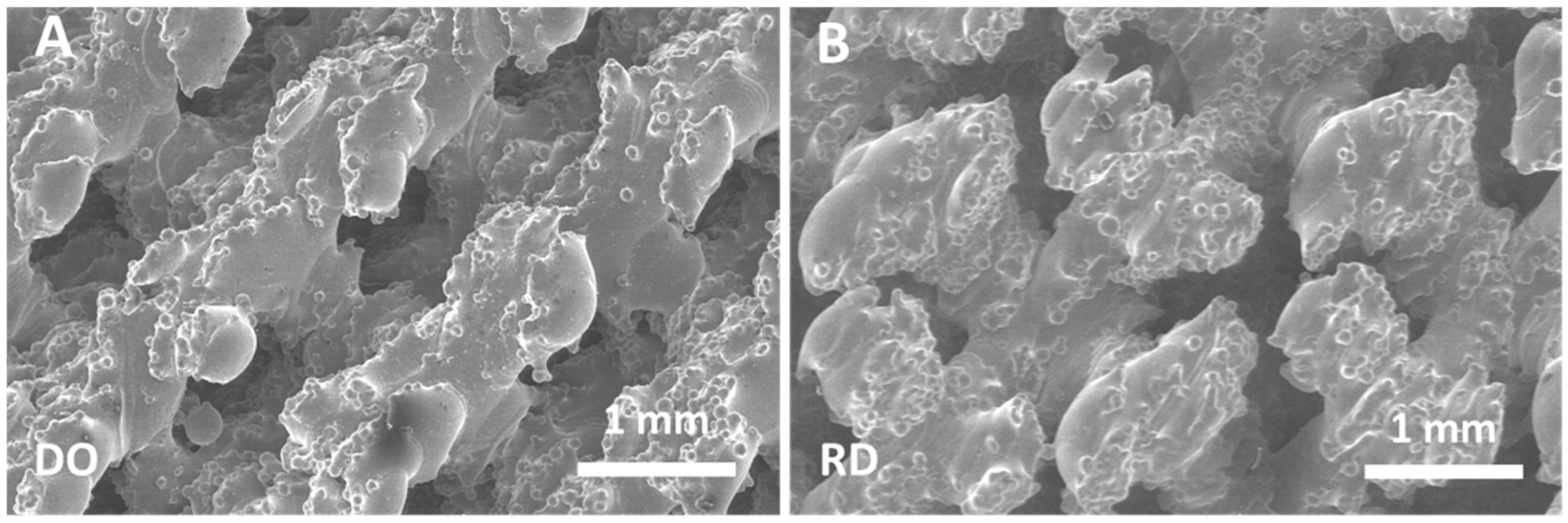
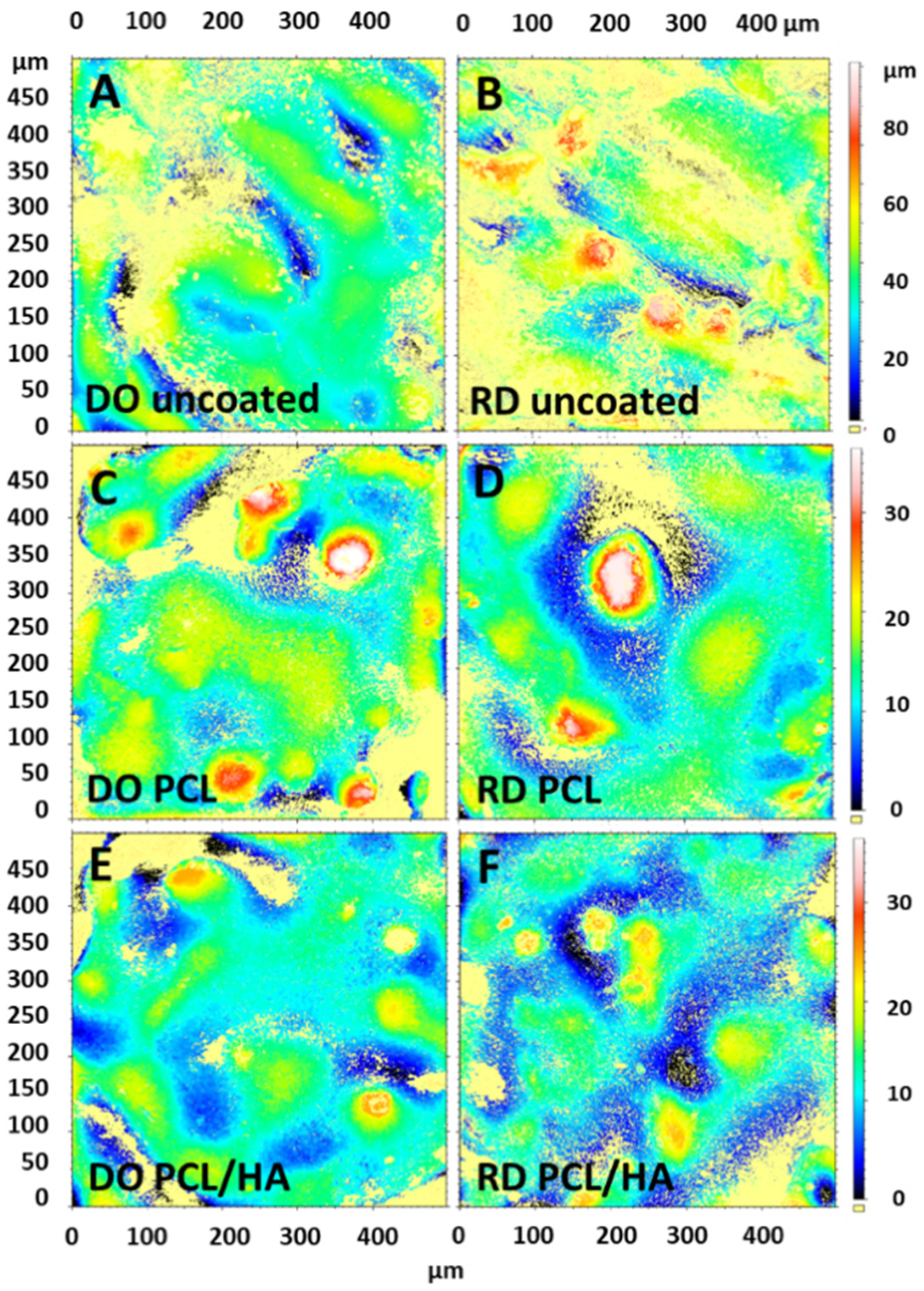
During the melting step of the EBM process, the electron beam provides enough energy to induce localized powder melting. However, in regions adjacent to the melted zone, the powder temperature does not reach the melting value so that large numbers of spherical titanium particles remain partially bonded to the walls of the melted pool, giving rise to the surface morphology reported in
Figure 4. Studies on surface roughness of EBM implants identified Ra = 24.9 μm as the upper limit value for positive effects on cell proliferation and differentiation [
47]. Roughness values of the scaffold surface reported in
Table 8 are well below this limit, even in uncoated condition, confirming that scaffolds manufactured with the EBM parameters reported in
Table 3 meet the needs of scaffold−host tissue interface for bone regeneration. Moreover, surface functionalization coating further decreases average surface roughness (
Table 8). Recent studies demonstrated beneficial effects in several biomedical applications of as-fabricated rippled surfaces in EBM processed alloys [
48,
49].
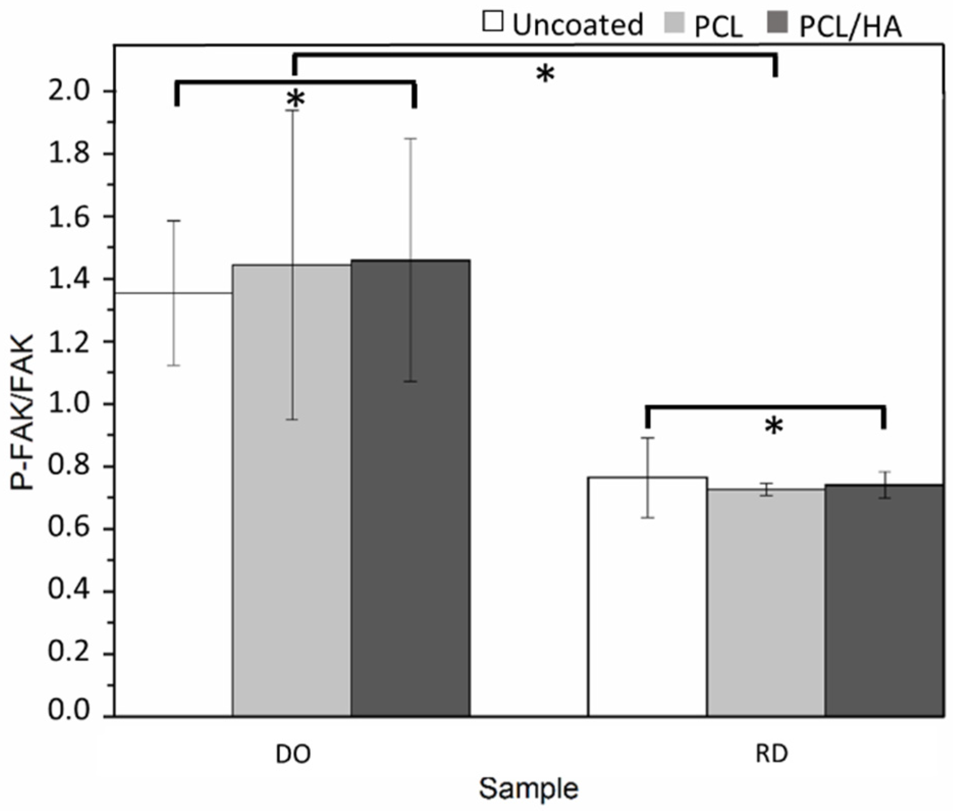
Concerning additional topology-connected performances of scaffolds, it is worth noting that the DO geometry generally provides a more suitable structure for cell vitality than RD, both at 24 h and 4 days. Metabolic protein quantification confirms the better biological response of DO against RD. Quantification of P-FAK on total FAK (
Figure 12), being the phosphorylation of FAK, the activator signal of the cell adhesion pathway, is indicative of a gentler environment for cell adhesion. Regardless of the percentage of viable cells present in scaffolds, a higher value of P-FAK/FAK of DO geometry corresponds to a greater number of viable cells attached to the scaffold. Therefore, since cell adhesion is a regulator of cellular proliferation, migration and differentiation [
50], this result suggests a better biological response of the DO unit cell geometry against RD, in perfect agreement with the numerical analysis by Li et al. [
6].
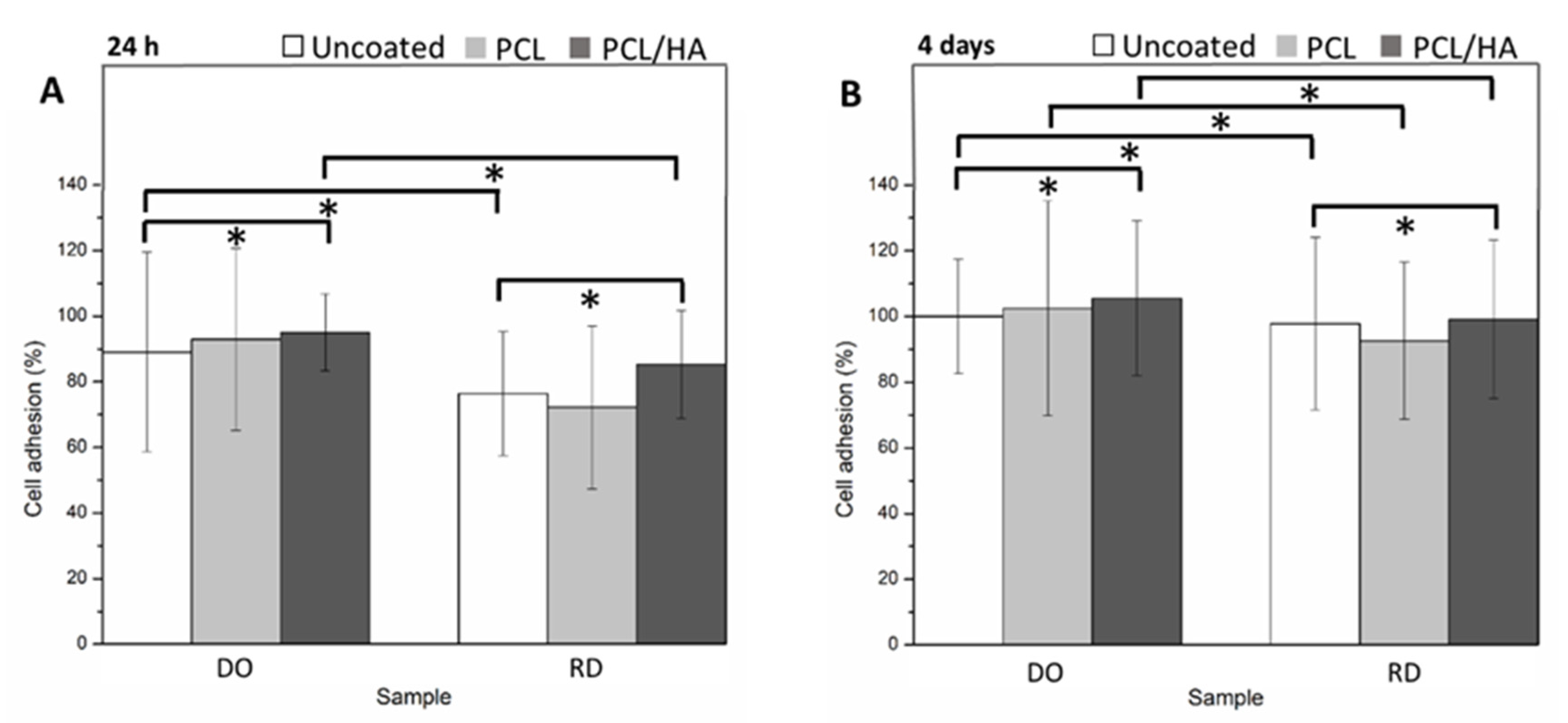
Further improvement in cell adhesion and proliferation was obtained by coating the scaffold surface with a single layer of PCL or PCL/HA. For both scaffold geometries (DO and RD) surface coating enhanced cell viability at 24 h and 4 days, especially in the presence of HA (
Figure 10). The PCL coating, with or without HA, promoted enhancement of P-FAK activation independently of the scaffold geometry (DO or RD).
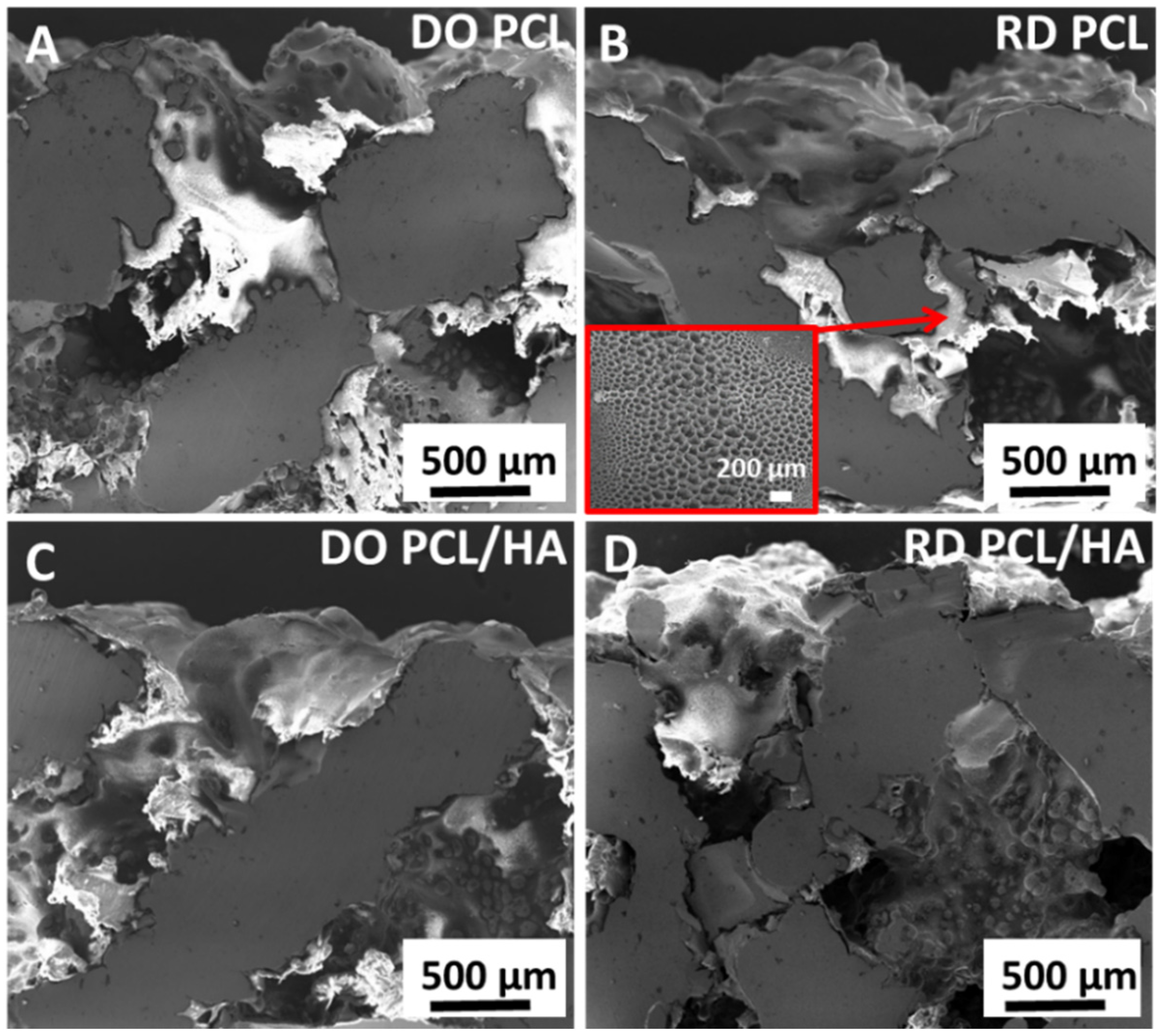
Coatings (
Figure 8) adhered to the substrate in varying thickness according to the surface topography developed by partially melted powder particles. Independently of coating type (PCL or PCL/HA), a porous structure formed on the coating surface due to solvent evaporation (inset in
Figure 8B). This porous structure promoted nutrient diffusion and osteointegration, thus supporting cell differentiation and proliferation [
44]. The coating changed the morphology and chemical composition of the scaffold surface, thus improving further surface biofunctions [
18]. Moreover, coating reduced the surface roughness, PCL/HA had the lowest Ra value (
Table 8) and improved the biological behavior of stem cells (
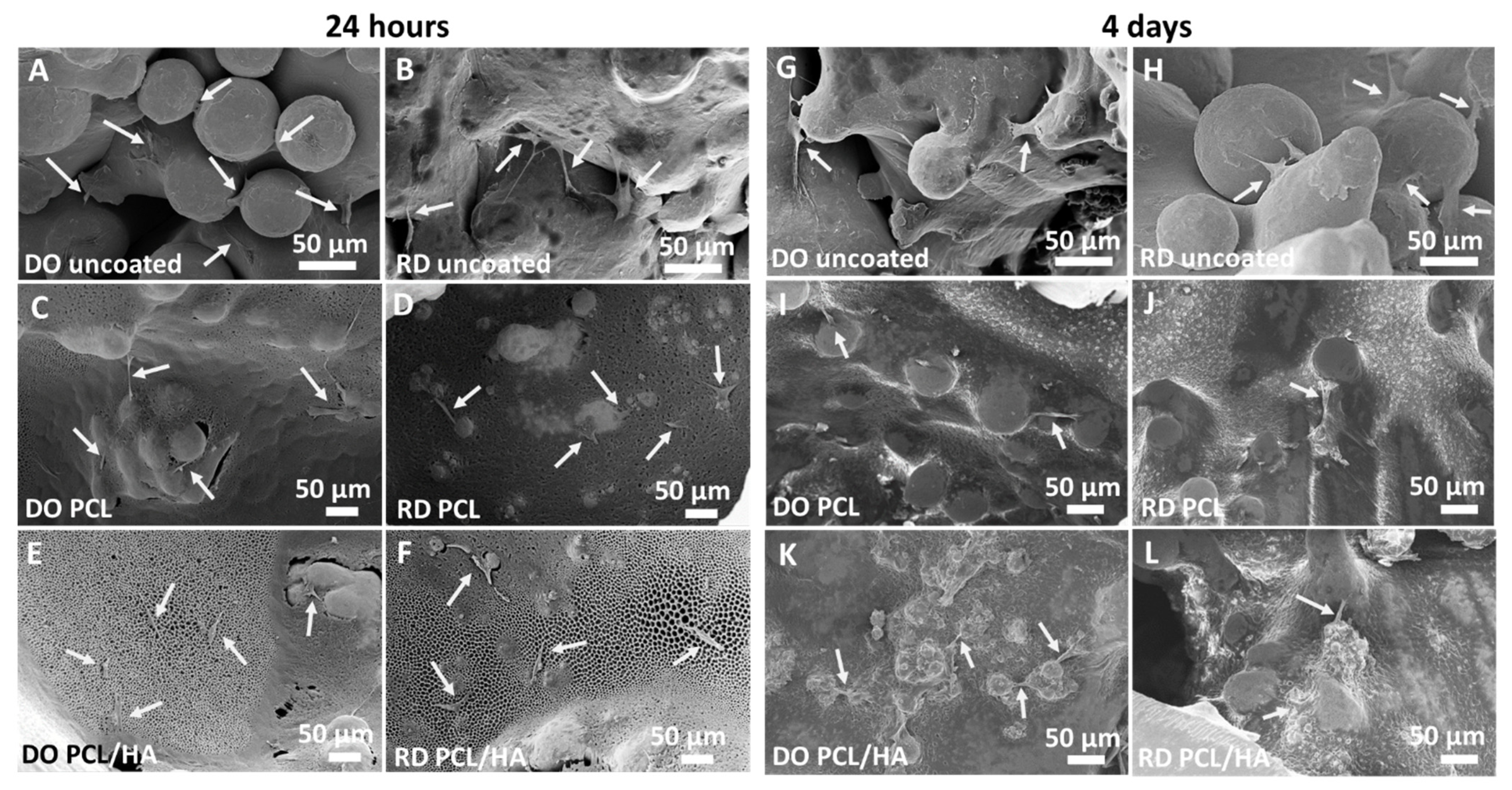
Figure 10B). SEM observations at 4 days incubation showed an absence of stem cells on the scaffold’s coated surface, suggesting penetration of hMSCs inside the scaffold (
Figure 11). Therefore, the investigated coatings enhanced cell penetration into the scaffold, with PCL/HA showing better performance due to lower surface roughness.
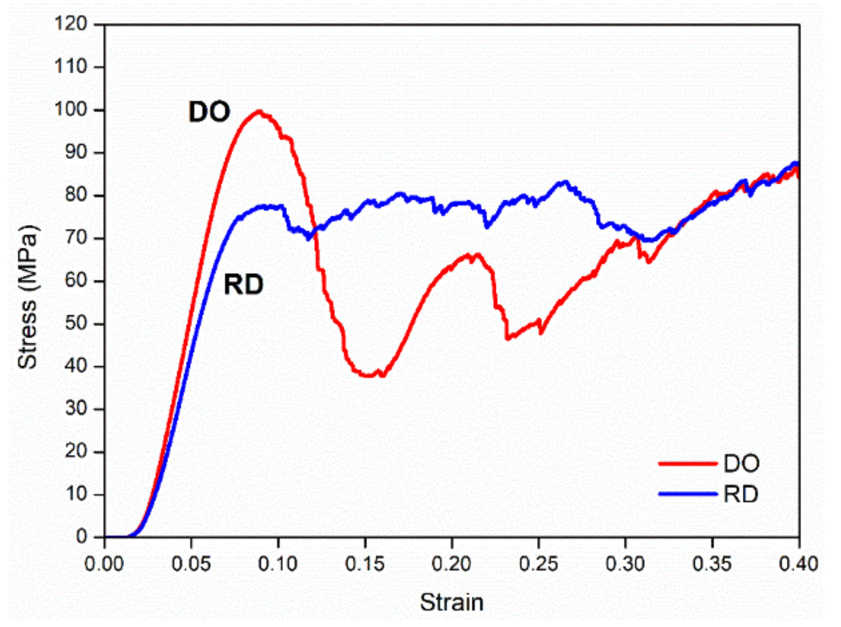
In terms of mechanical behavior under uniaxial compressive testing (
Figure 7) scaffold unit cell geometry seemed to be the most influencing parameter, although powder aggregation effects in the scaffold core must be considered. Stress–strain curves shown in
Figure 7 for DO and RD unit cell geometry exhibited a general shape in agreement with the results in literature for the same cell topology [
5,
43]. The DO curve grew rapidly up to maximum stress value, corresponding to the compression strength, then large oscillations due to collapse of unit cells under compressive load followed. The collapse mechanism was clearly described by Ahmadi et al. [
43] and Del Guercio et al. [
51] In contrast, the RD curve after its first rise showed small oscillations around the same average stress value (
Figure 7), in agreement with the results in literature [
5,
43]. However, contrary to the results in literature, DO and RD curves in
Figure 7 reached the same stress value in the final part of the curve at high strain values. The two curves were completely superimposed above 35% strain, when the unit cells were all collapsed, and the scaffold structure arrived at compaction (
Figure 7). Ahmadi et al. [
43] reported the trend of compression strength and yield stress as a function of relative density for DO and RD geometries, showing that for relative density below 25% the two curves were superimposed, while for higher values RD always exhibited higher mechanical properties against DO. Ahmadi et al. [
43] attributes the lower mechanical properties of DO to the unit cell geometry which is relatively simple and different struts provide only limited support to each other during compression. The relative density of our scaffolds, obtained by experimental calculation of porosity from XCT analysis, was 37% with compression strength of RD (78 MPa) lower than DO (99 MPa), as reported in
Table 7. Generally, the mechanical behavior of our scaffolds strongly differed from the results of Li et al. [
5] and Ahmadi et al. [
43] for similar structures (
Table 7). In particular, the large size of struts (ranging from 800 to 1000 µm) in our scaffolds determined the elastic behavior (Young modulus) and compression strength of DO and RD geometries (
Table 7). Following Ahmadi et al. [
43], the more complex unit cell geometry (RD) exhibited lower elastic properties (
Table 7), while absolute values of Young modulus were always lower than the values from Li et al. [
5] for similar cell geometries with lower strut size and lower relative density (
Table 7). Therefore, higher strut size gives rise to stiffer structures with different behaviors for different unit cell geometries. In our case, both strut size and the absence of structural defects inside the struts (
Figure 5) were responsible for higher compression strength of DO with respect to RD (
Table 7).
On compression, in the simpler DO geometry failure of a single strut caused collapse of an entire elementary unit cell, then producing the large oscillations visible in the DO curve in
Figure 7. As the collapse of elementary unit cells occurred from outside to inside during compression, the first part of the stress–strain curve (
Figure 7) was not influenced by the residual powder stored in the scaffold core (
Figure 5). However, when all external elementary unit cells had collapsed, elementary unit cells in the scaffold core that were partially filled with sintered residual powder, started to deform. On collapse of core elementary unit cells, the scaffold’s mechanical properties became dependent on sintered residual powder, which increased compressive stress and stress on struts in the longitudinal direction perpendicular to the compressive force. In this way, differences in mechanical properties linked to different elementary unit cell geometry vanished, overruled by the presence of residual powder, so stress–strain curves of DO and RD unit cells coincided. It is worth noting that the compression strength at 40% of our scaffolds is very close to the experimental value of cortical bone (
Table 7), suggesting that the presence of residual sintered powder did not deteriorate the mechanical performance of the scaffolds.

 ,
, 


