
Parameters Tailoring on the Deposition of Hydroxyapatite by Pulsed Electrical Discharge

 and
and 
Abstract
:1. Introduction
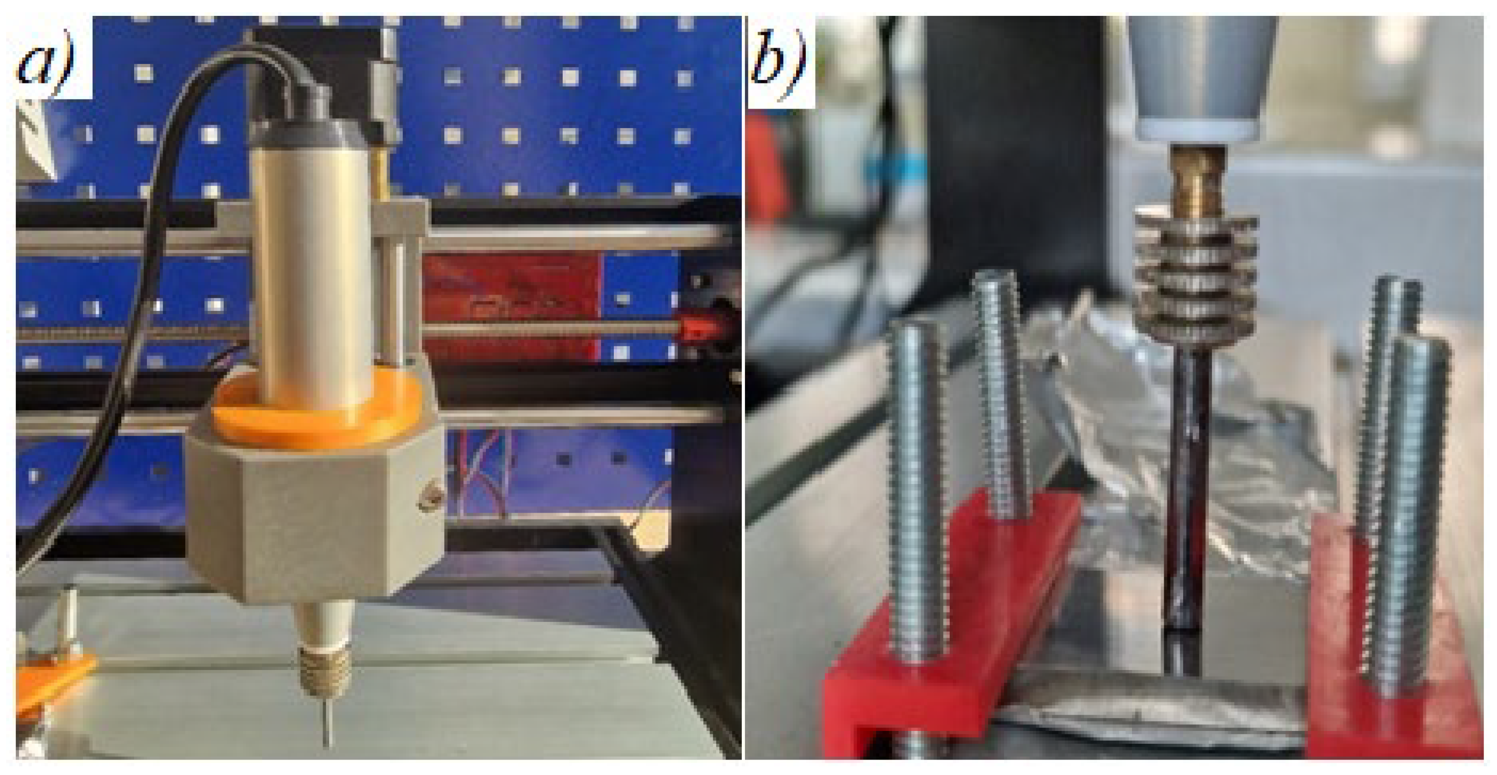
2. Work Methodology, Materials, and Equipment Used in the Research
- Establishment of independent parameters, ranges, and limits of variation.
- Establishment of second-order orthogonal compositional central programming (concrete experimental conditions).
- Determination of the coefficients of the regression equation.
- Determination of the dispersion of the reproducibility of the experiment (a minimum of three experiments were performed under identical conditions).
- Statistical verification of the coefficients of the nonlinear model.
- Verification of the hypothesis regarding concordance of the adopted nonlinear model.
3. Results, Interpretations
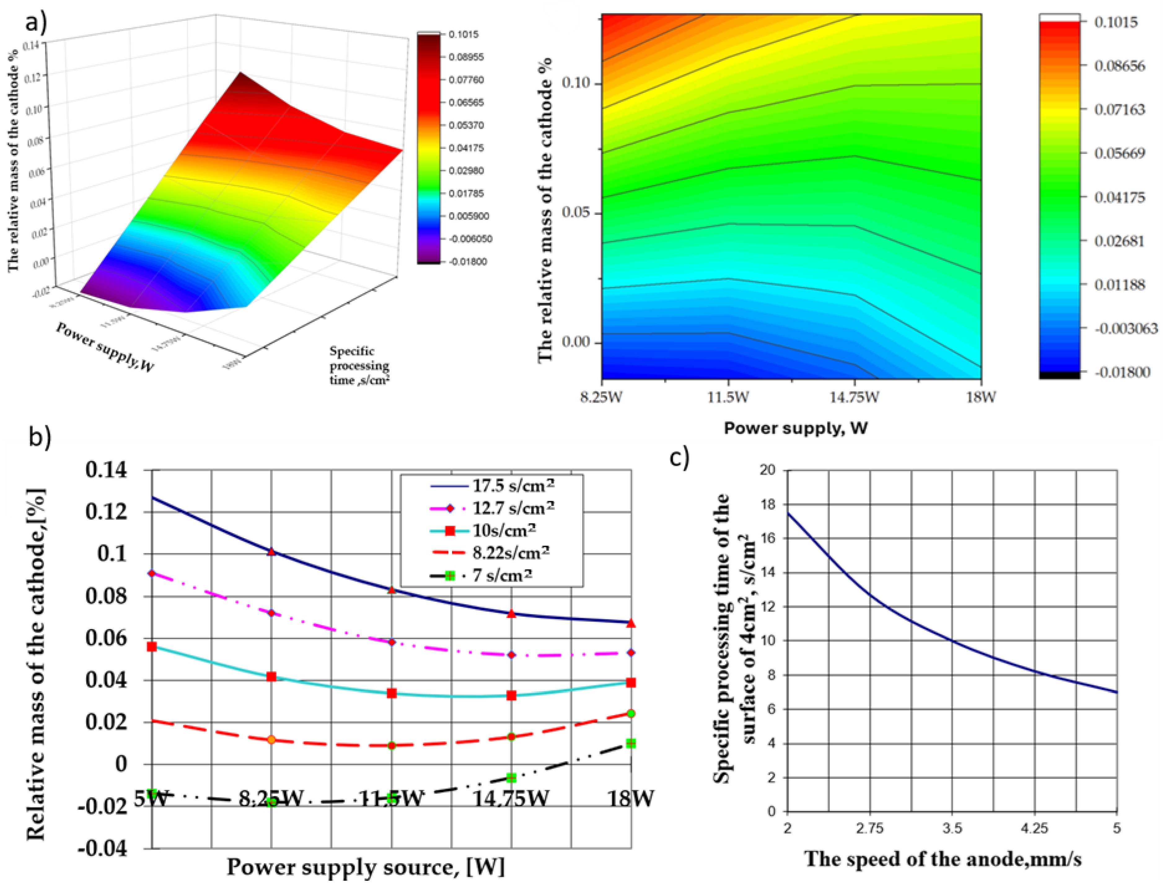
- A high anode traversal velocity over the cathode surface, associated with the lower power values of the source (5 W in this group of experiments), makes it possible to tear off the particles from the surface of the cathode in the interelectrode plasma cloud, resulting in relative mass loss.
- Observation: The power of the source was considerably lower than the energy released during the electrical impulse discharge in the interelectrode plasma cloud.
- The most significant relative mass increase of the cathode corresponds to the lowest power of the power source (5 W in this case) associated with the longest specific processing time of the cathode (the lowest anode traversal velocity over the cathode surface), which increases the probability of redeposition of any detachment from the cathode surface along with the polar transfer and deposition of the products resulting from anodic erosion.
- An increase in the power of the electrical energy supply source affects the relative mass variation of the cathode, which is strictly dependent on the specific time of its surface processing (the velocity of the anode movement on the cathode surface).
- The decrease in the specific time for processing the cathode surface within the limits of 17.5 ÷ 7.0 s/cm2 associated with variations in the power of the energy supply within the limits of 5.0 ÷ 11.5 W implies a decrease in the relative mass of the cathode, which grows more significant as the specific processing time increases.
- When the power of 11.5 W of the supply source is exceeded, the effect is much more attenuated and occurs at specific processing times below 10 s/cm2, even when the relative mass variations of the cathode are increased. The effects are related to, and depend on, the ratio between the rate of particle removal from the cathode’s surface and the rate of deposition on its surface. Regardless of the situation, the most substantial relative mass increase recorded by the cathode was obtained at the reduced values of the power of the electrical energy supply source (at the lower limit of the tested range) and the highest value of the specific processing time.
4. Conclusions
Author Contributions
Funding
Institutional Review Board Statement
Informed Consent Statement
Data Availability Statement
Conflicts of Interest
References
- Cavalu, S.; Fritea, L.; Brocks, M.; Barbaro, K.; Murvai, G.; Costea, T.O.; Antoniac, I.; Verona, C.; Romani, M.; Latini, A.; et al. Novel Hybrid Composites Based on PVA/SeTiO2 Nanoparticles and Natural Hydroxyapatite for Orthopedic Applications: Correlations between Structural, Morphological and Biocompatibility Properties. Materials 2020, 13, 2077. [Google Scholar] [CrossRef] [PubMed]
- Fadeeva, I.V.; Kalita, V.I.; Komlev, D.I.; Radiuk, A.A.; Fomin, A.S.; Davidova, G.A.; Fursova, N.K.; Murzakhanov, F.F.; Gafurov, M.R.; Fosca, M.; et al. In Vitro Properties of Manganese-Substituted Tricalcium Phosphate Coatings for Titanium Biomedical Implants Deposited by Arc Plasma. Materials 2020, 13, 4411. [Google Scholar] [CrossRef] [PubMed]
- Antoniac, I.; Miculescu, F.; Cotrut, C.; Ficai, A.; Rau, J.V.; Grosu, E.; Antoniac, A.; Tecu, C.; Cristescu, I. Controlling the Degradation Rate of Biodegradable Mg–Zn-Mn Alloys for Orthopedic Applications by Electrophoretic Deposition of Hydroxyapatite Coating. Materials 2020, 13, 263. [Google Scholar] [CrossRef]
- Fosca, M.; Streza, A.; Antoniac, I.V.; Vadalà, G.; Rau, J.V. Ion-Doped Calcium Phosphate-Based Coatings with Antibacterial Properties. J. Funct. Biomater. 2023, 14, 250. [Google Scholar] [CrossRef]
- Mocanu, A.M.; Miculescu, F.; Stan, G.E.; Tite, T.; Miculescu, M.; Țierean, M.H.; Pascu, A.; Ciocoiu, R.C.; Butte, T.M.; Ciocan, L.T. Development of ceramic coatings on titanium alloy substrate by laser cladding with pre-placed natural derived-slurry: Influence of hydroxyapatite ratio and beam power. Ceram. Int. 2023, 49, 10445–10454. [Google Scholar] [CrossRef]
- Niakan, A.; Ramesh, S.; Ganesan, P.; Tan, C.Y.; Purbolaksono, J.; Chandran, H.; Ramesh, S.; Teng, W.D. Sintering behaviour of natural porous hydroxyapatite derived from bovine bone. Ceram. Int. 2015, 41, 3024–3029. [Google Scholar] [CrossRef]
- Liu, S.; Shin, Y.C. Additive manufacturing of Ti6Al4V alloy: A review. Mater. Des. 2019, 164, 107552. [Google Scholar] [CrossRef]
- Lin, N.; Li, D.; Zou, J.; Xie, R.; Wang, Z.; Tang, B. Surface Texture-Based Surface Treatments on Ti6Al4V Titanium Alloys for Tribological and Biological Applications: A Mini Review. Materials 2018, 11, 487. [Google Scholar] [CrossRef]
- Mohseni, E.; Zalnezhad, E.; Bushroa, A.R. Comparative Investigation on the Adhesion of Hydroxyapatite coating on Ti-6Al-4V Implant: A Review Paper. Int. J. Adhes. Adhes. 2013, 48, 238–257. [Google Scholar] [CrossRef]
- Gomes, D.S.; Santos, A.M.C.; Neves, G.A.; Menezes, R.R. A brief review on hydroxyapatite production and use in biomedicine. Ceramics 2019, 65, 282–302. [Google Scholar] [CrossRef]
- Vranceanu, D.M.; Ionescu, I.C.; Ungureanu, E.; Cojocaru, M.O.; Vladescu, A.; Cotrut, C.M. Magnesium doped hydroxyapatite-based coatings obtained by pulsed galvanostatic electrochemical deposition with adjustable electrochemical behavior. Materials 2020, 10, 727. [Google Scholar] [CrossRef]
- Surmenev, R.A.; Surmeneva, M.A. A critical review of decades of research on calcium phosphate–based coatings: How far are we from their widespread clinical application? Curr. Opin. Biomed. Eng. 2019, 10, 35–44. [Google Scholar] [CrossRef]
- Safavi, M.S.; Walsh, F.C.; Surmeneva, M.A.; Surmenev, R.A.; Allafi, J.K. Electrodeposited Hydroxyapatite-Based Biocoatings: Recent Progress and Future Challenges. Coatings 2021, 11, 110. [Google Scholar] [CrossRef]
- Beig, B.; Liaqat, U.; Naiazi, M.F.K.; Douna, I.; Zahoor, M.; Niazi, M.B.K. Current challenges and innovative developments in hydroxyapatite based coatings on metallic materials for bone implantation: A review. Coatings 2022, 10, 1249. [Google Scholar] [CrossRef]
- Ong, J.L.; Chan, D.C.N. Hydroxyapatite and its use as coatings in dental implants: A review. Biomed. Eng. 2000, 28, 667–707. [Google Scholar] [CrossRef]
- Pavel, T.; Petru, S. Tehnologii de Prelucrare a Materialelor Conductibile cu Aplicarea Descărcărilor Electrice in Impuls; Tehnica-Info Chișinău: Chișinău, Moldova, 2008. [Google Scholar]
- Cojocaru, M.O.; Brânzei, M.; Cotruț, M.C.; Lăptoiu, Ș.A. Procedeu de Depunere a Hidroxiapatitei prin Metoda Electroeroziunii și Transferului Polar (Aliere prin Scântei Electrice). Patent Application No. A 100455, 16 August 2023. [Google Scholar]
- Barile, C.; Casavola, C.; Pappalettera, G.; Renna, G. Advancements in electrospark deposition (ESD) technique: A short review. Coatings 2022, 2, 1536. [Google Scholar] [CrossRef]
- Salmaliyan, M.; Ghaeni, F.M.; Ebrahimnia, M. Effect of electro spark deposition process parameters on WC-Co coating on H13 steel. Surf. Coat. Technol. 2017, 321, 81–89. [Google Scholar] [CrossRef]
- Pliszka, I.; Radek, N. Corrosion resistance of WC-Cu coatings produced by electrospark deposition. Procedia Eng. 2017, 192, 707–712. [Google Scholar] [CrossRef]
- Hasanabadi, M.F.; Ghaini, F.M.; Ebrahimnia, M.; Shahverdi, H.R. Production of amorphous and nanocrystalline iron based coatings by electro-spark deposition process. Procedia Eng. 2015, 270, 95–101. [Google Scholar] [CrossRef]
- Rukanskis, M. Control of Metal Surface Mechanical and Tribological Characteristics Using Cost Effective Electro-Spark Deposition. Surf. Eng. Appl. Electrochem. 2018, 55, 607–619. [Google Scholar] [CrossRef]
- Cheng, L.; Xiong, X.; Dong, S. TiB2/Ni coatings on surface of copper alloy electrode prepared by electrospark deposition. Trans. Nonferrous Met. Soc. China 2011, 21, 317–321. [Google Scholar] [CrossRef]
- Wei, X.; Chen, Z.; Zhong, J.; Xiang, Y. Feasibility of preparing Mo2FeB2-based cermet coating by electrospark deposition on high speed steel. Surf. Coat. Technol. 2016, 296, 58–64. [Google Scholar] [CrossRef]
- Chen, C.J.; Wang, M.C.; Wang, D.S.; Liang, H.S.; Feng, P. Characterisations of electrospark deposition Stellite 6 alloy coating on 316L sealed valve used in nuclear power plant. Mater. Sci. Technol. 2013, 26, 276–280. [Google Scholar] [CrossRef]
- Ruijun, W.; Weiping, W.; Hehong, T.; Yufen, L. Repair heavy-duty generator rotor shaft by electro spark deposition process. Trans. JWRI 2010, 39, 164–165. [Google Scholar] [CrossRef]
- Kuptsov, K.A.; Antonyuk, M.N.; Bondarev, A.V.; Sheveyko, A.N.; Shtansky, D.V. Electrospark deposition of wear and corrosion resistant Ta(Zr)C-(Fe, Mo, Ni) coatings to protect stainless steel from tribocorrosion in seawater. Wear 2021, 486–487, 204094. [Google Scholar] [CrossRef]
- Dimitriu, S.; Taloi, D. Metode de Modelare Matematica a Proceselor Tehnologice; Printech: Bucharest, Romania, 2014. [Google Scholar]
- Irfan, M.; Waqas, S.; Arshad, U.; Khan, J.A.; Legutko, S.; Kruszelnicka, I.; Ginter-Kramarczyk, D.; Rahman, S.; Skrzypczak, A. Response Surface Methodology and Artificial Neural Network Modelling of Membrane Rotating Biological Contactors for Wastewater Treatment. Materials 2022, 15, 1932. [Google Scholar] [CrossRef]


| Factors | Z1-Power of the Feeding Source, W | The Z2-Moving Velocity of the Anode, mm/s |
|---|---|---|
| Code | X1 | X2 |
| Base Level, Zi0 | 11.5 | 3.5 |
| Level of Variation, Δzi | 6.5 | 1.5 |
| Superior Level (+1); Zi0 + Δzi | 18 | 5 (7 s/cm2) |
| Inferior Level (−1); Zi0 − Δzi | 5 | 2 (17.5 s/cm2) |
| Experiment Number | X0 | X1 | X2 | X1X2 | |||
|---|---|---|---|---|---|---|---|
| 1 | +1 | −1 | −1 | +1 | +1/3 | +1/3 | 0.153 |
| 2 | +1 | −1 | +1 | −1 | +1/3 | +1/3 | −0.005 |
| 3 | +1 | +1 | +1 | +1 | +1/3 | +1/3 | 0.005 |
| 4 | +1 | +1 | −1 | −1 | +1/3 | +1/3 | 0.08 |
| 5 | +1 | +1 | 0 | 0 | +1/3 | −2/3 | 0.052 |
| 6 | +1 | −1 | 0 | 0 | +1/3 | −2/3 | 0.042 |
| 7 | +1 | 0 | +1 | 0 | −2/3 | +1/3 | −0.011 |
| 8 | +1 | 0 | −1 | 0 | −2/3 | +1/3 | 0.053 |
| 9 | +1 | 0 | 0 | 0 | −2/3 | −2/3 | 0.018 |
| Conclusion | ||||
|---|---|---|---|---|
| = 8.0377 · 10−6 | 0.00283 | - | b0 = 0.043; b1 = −0.00883; b2 = −0.00495; b12 = 0.0207; b11 = 0.0138; b22 = 0.0085 | - |
| = 2.411 · 10−5 | 0.00491 | 0.01100 | b0-OK | |
| = 1.205 · 10−5 | 0.00347 | 0.00784 | b1;b2-OK | |
| = 1.808 · 10−5 | 0.00425 | 0.00960 | b12-OK | |
| = 3.617 · 10−5 | 0.00601 | 0.01360 | b11-OK |
| Expression Number | Yu | |||
|---|---|---|---|---|
| 1 | 0.018 | 3.4 · 10−3 | 1.156 · 10−5 | ϑ2 = 3 − 1 = 2 |
| 2 | 0.005 | 9.6 · 10−3 | 9.216 · 10−5 | |
| 3 | 0.021 | 6.4 · 10−3 | 4.096 · 10−5 | |
| = 0.0146 | = 7.234 · 10−5 |
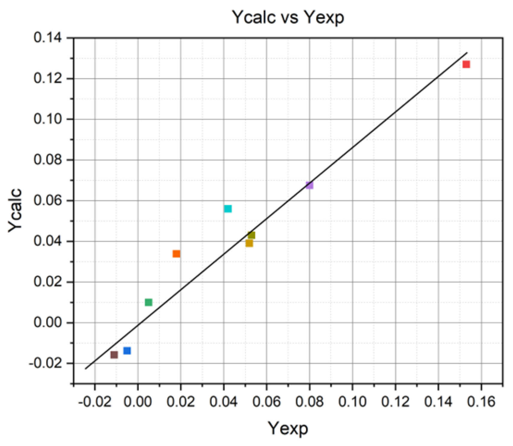
| Number | Yexp | Ycalc | ||
|---|---|---|---|---|
| 1 | +0.153 | +0.127 | 6.76 · 10−4 | = 9 − 5 = 4 |
| 2 | −0.005 | −0.0138 | 7.74 · 10−5 | |
| 3 | +0.005 | +0.0100 | 2.5 · 10−5 | |
| 4 | +0.08 | +0.0675 | 1.56 · 10−4 | |
| 5 | +0.052 | +0.039 | 1.69 · 10−4 | |
| 6 | +0.042 | +0.056 | 1.96 · 10−4 | |
| 7 | −0.011 | −0.0158 | 2.304 · 10−5 | |
| 8 | +0.053 | +0.043 | 1 · 10−4 | |
| 9 | +0.018 | +0.0338 | 2.49 · 10−4 | |
| ΣΔY2 = 16.7 · 10−4 | ||||
Disclaimer/Publisher’s Note: The statements, opinions and data contained in all publications are solely those of the individual author(s) and contributor(s) and not of MDPI and/or the editor(s). MDPI and/or the editor(s) disclaim responsibility for any injury to people or property resulting from any ideas, methods, instructions or products referred to in the content. |
© 2024 by the authors. Licensee MDPI, Basel, Switzerland. This article is an open access article distributed under the terms and conditions of the Creative Commons Attribution (CC BY) license (https://creativecommons.org/licenses/by/4.0/).
Share and Cite
Laptoiu, S.A.; Cojocaru, M.O.; Miculescu, M.; Branzei, M. Parameters Tailoring on the Deposition of Hydroxyapatite by Pulsed Electrical Discharge. Materials 2024, 17, 4583. https://doi.org/10.3390/ma17184583
Laptoiu SA, Cojocaru MO, Miculescu M, Branzei M. Parameters Tailoring on the Deposition of Hydroxyapatite by Pulsed Electrical Discharge. Materials. 2024; 17(18):4583. https://doi.org/10.3390/ma17184583
Chicago/Turabian StyleLaptoiu, Stefan Alexandru, Mihai Ovidiu Cojocaru, Marian Miculescu, and Mihai Branzei. 2024. "Parameters Tailoring on the Deposition of Hydroxyapatite by Pulsed Electrical Discharge" Materials 17, no. 18: 4583. https://doi.org/10.3390/ma17184583