
The Influence of Elastic Support of Component Glass Panes on Deflection and Stress in Insulating Glass Units—Analytical Model


Abstract
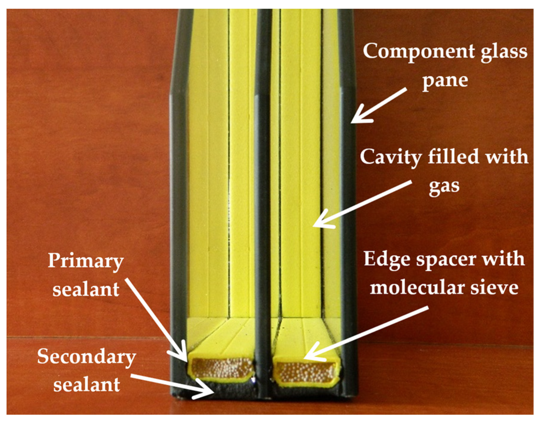
:1. Introduction
2. Materials and Methods
2.1. Base Model
- p0, T0, v0—initial parameters of gas in the cavity: pressure [kPa], temperature [K] and volume [m3]; parameters of the production process; it is assumed that under these conditions, the resultant load equals 0;
- pop, Top—operating parameters: pressure [kPa] and temperature [K] in the cavity;
- pa—current atmospheric pressure [kPa];
- αv,ex, αv,in—proportionality coefficients describing the change in the volume of the cavity caused by the deflection of a given glass under a unit load per area [m5/kN];
- qz,ex—wind load [kN/m2].
- α′v—dimensionless coefficient [−];
- a—width of the glass pane [m];
- D—flexural rigidity of glass pane [kNm];
- E—Young’s modulus of glass [kPa];
- d—glass pane thickness [m];
- μ—Poisson’s ratio of glass [−].
- α′w—dimensionless coefficient [-].
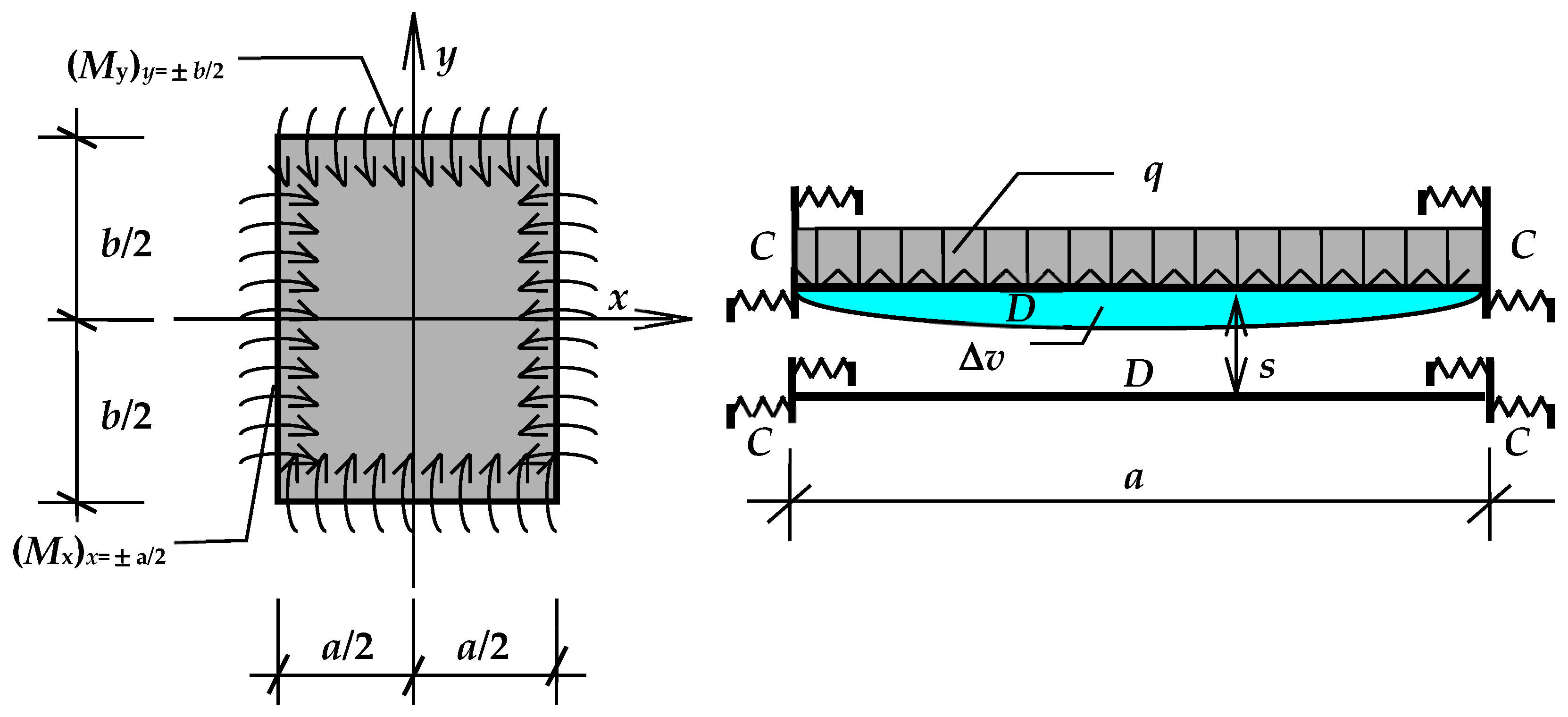
2.2. Deflection and Change of Cavity Volume in IGUs with Elastically Supported Glass Panes
2.3. Stress in Elastically Supported Glass Panes
- wq, wMy, wMx—deflection of a simply supported pane under load q and deflections due to supporting moments My, and Mx [kNm/m].
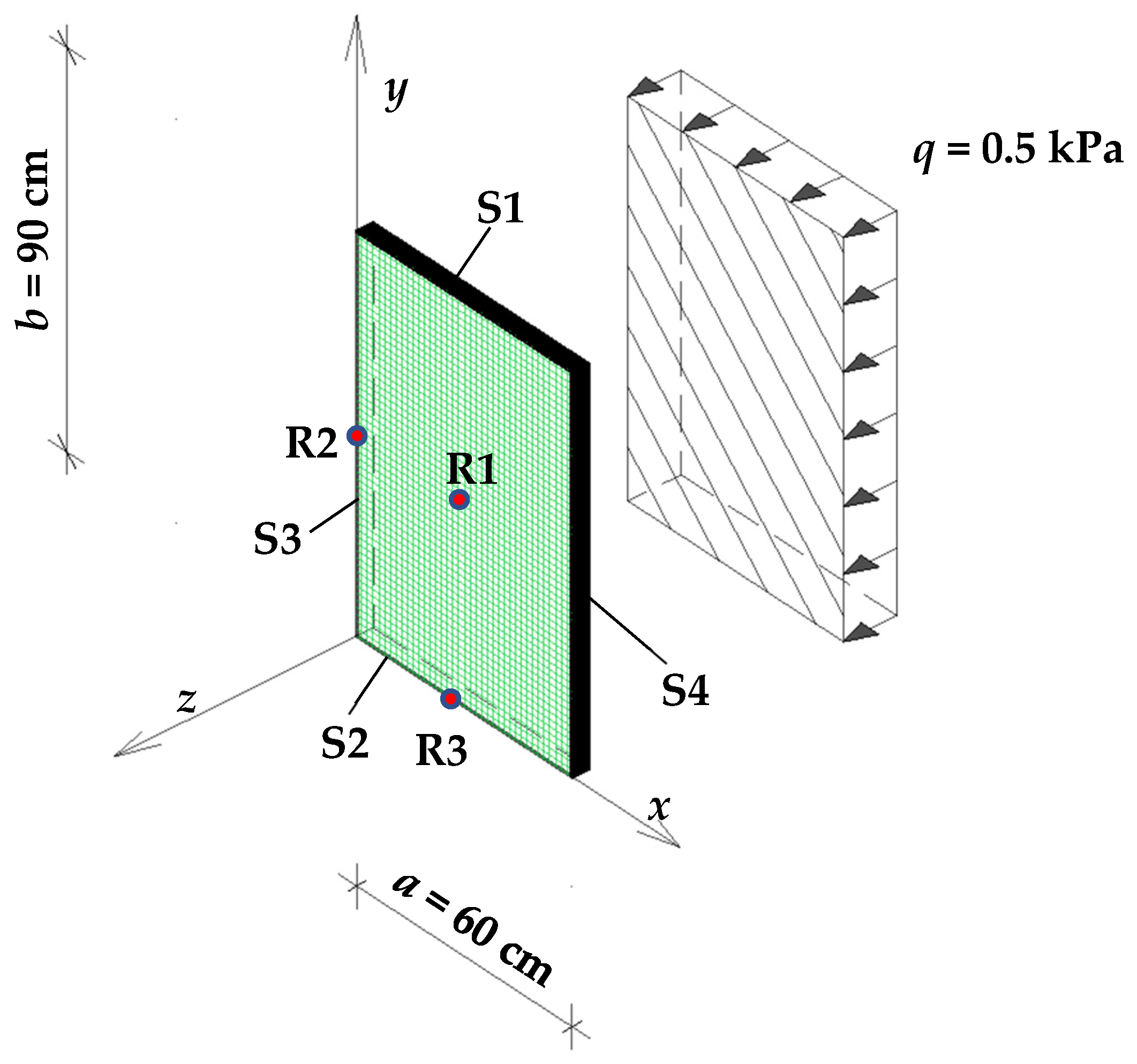
2.4. Reference IGU Parameters
2.5. Numerical Validation of the Analytical Model
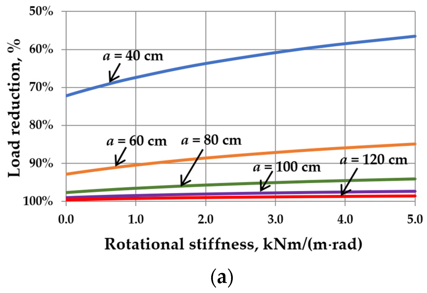
3. Results
3.1. Scope of Analysis
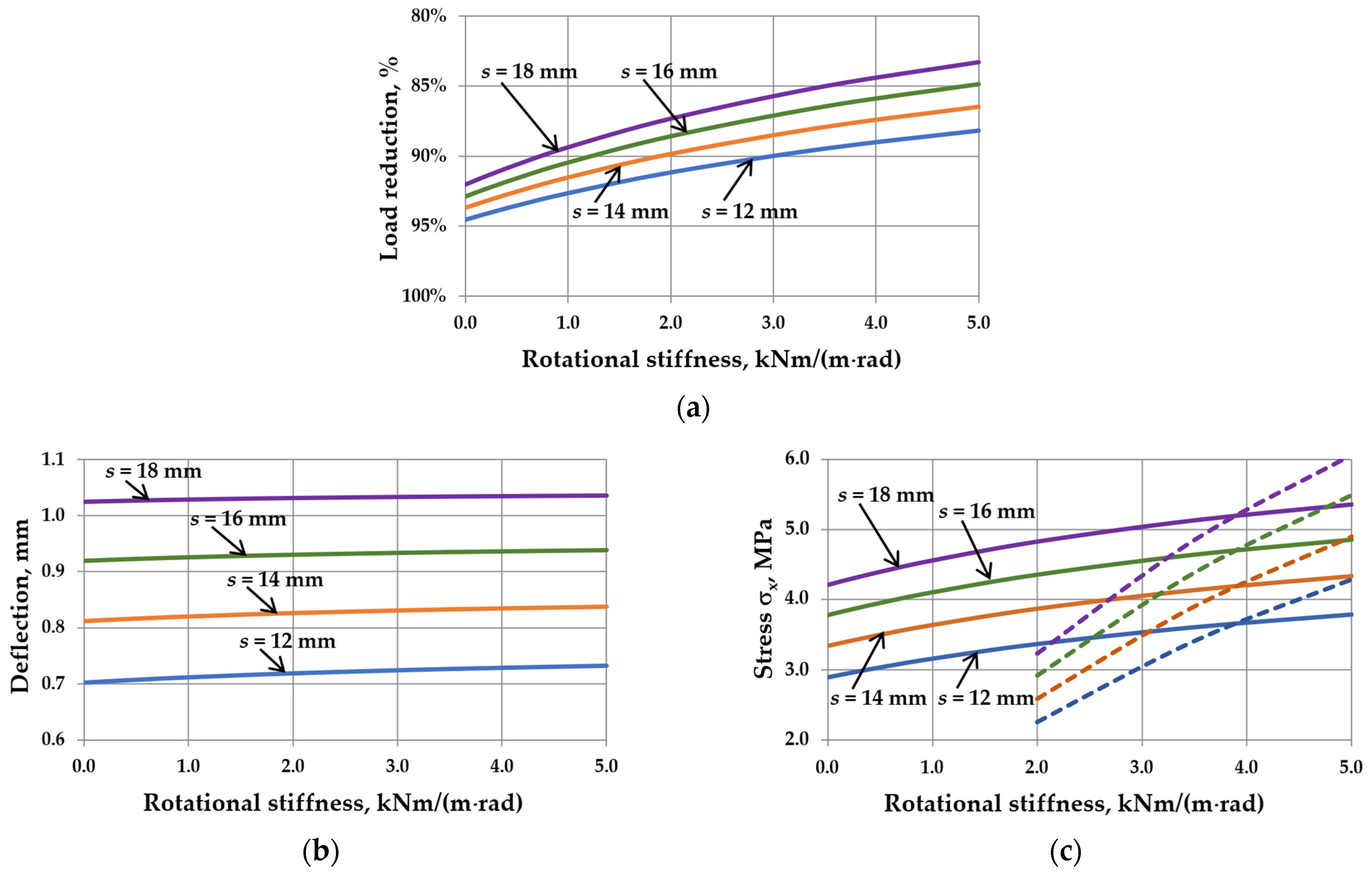
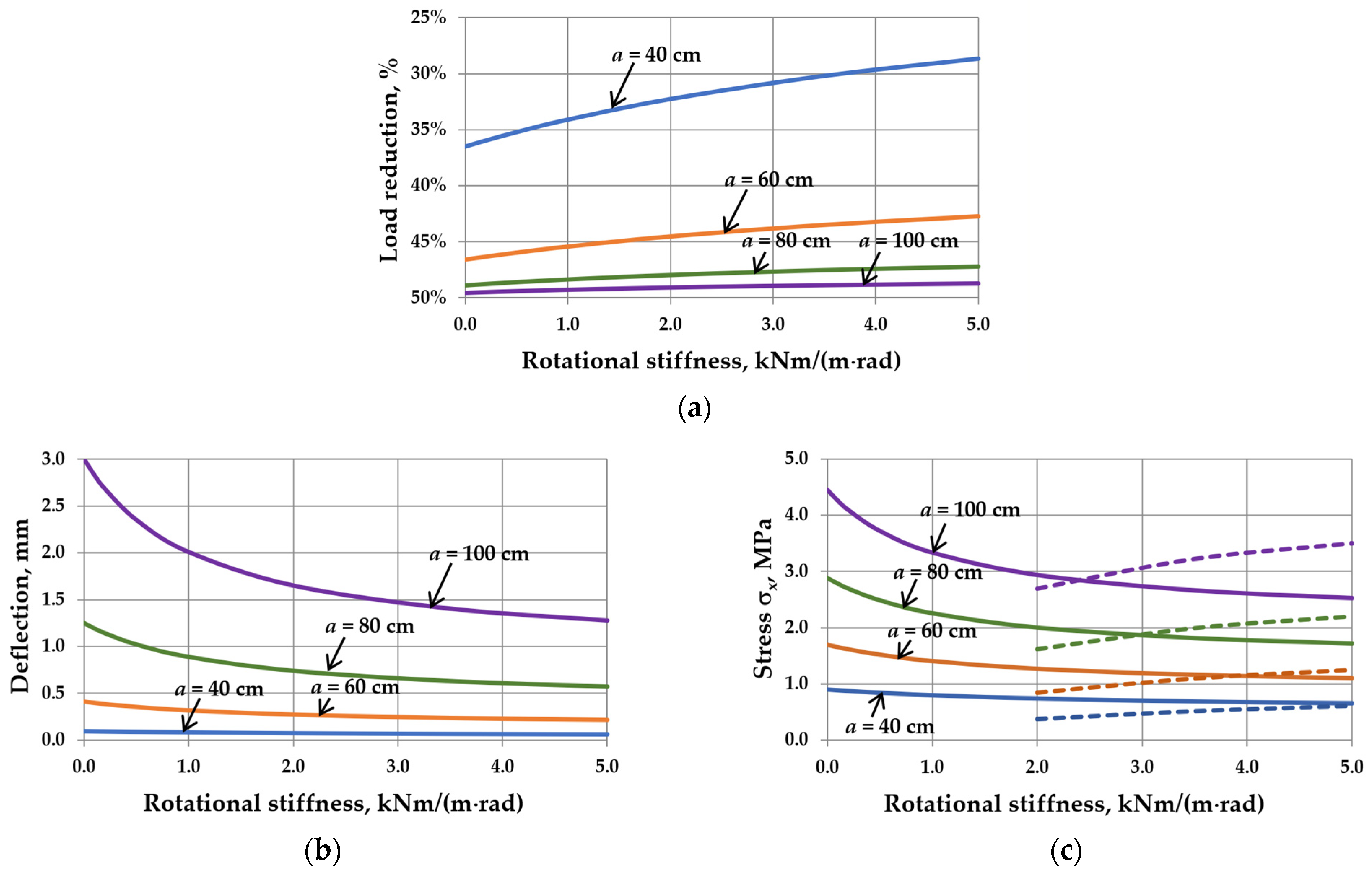
3.2. Symmetrical Load—Atmospheric Pressure Changes
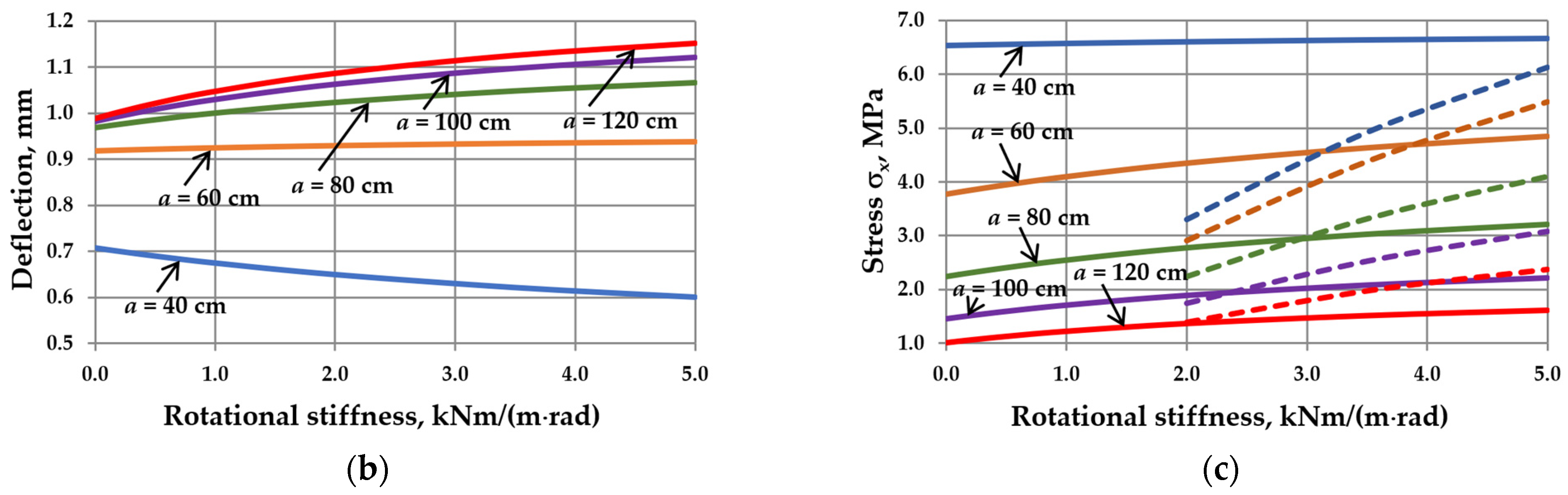
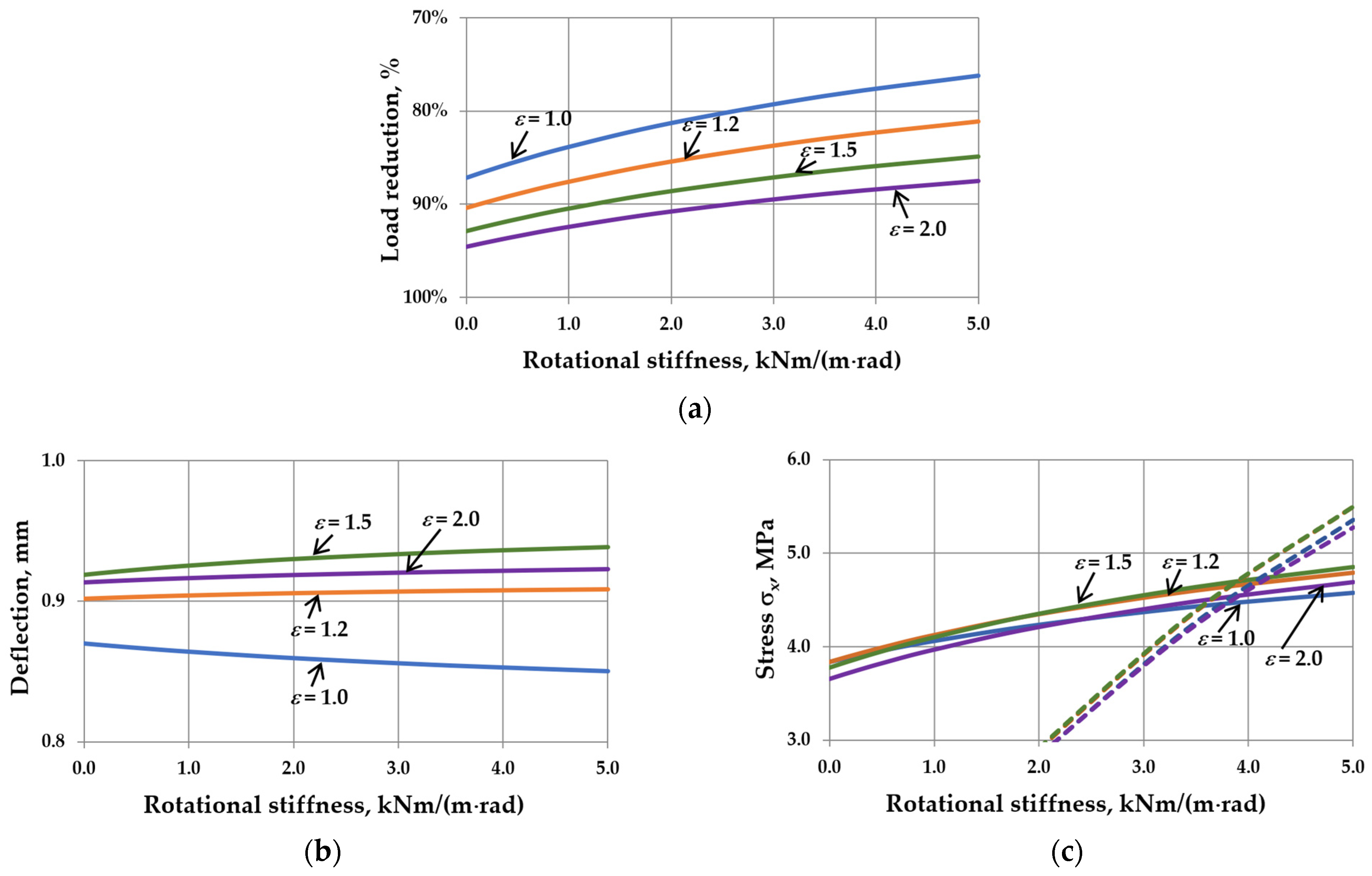
3.3. Asymmetrical Load—Wind Pressure
4. Discussion
5. Conclusions and Further Work
Supplementary Materials
Funding
Institutional Review Board Statement
Informed Consent Statement
Data Availability Statement
Conflicts of Interest
Nomenclature
| A | auxiliary parameter [m3] |
| a | width (of IGU) [m] or [cm] |
| B | auxiliary parameters [m5/kN] |
| b | length (of IGU) [m] or [cm] |
| C | rotational stiffness [kNm/(m·rad)] |
| D | flexural rigidity (of component glass pane) [kNm] |
| d | thickness (of component glass pane) [m] or [mm] |
| E | Young’s modulus [kPa] or [GPa] |
| F | numeric sequence [kNm/m] |
| F′ | numeric sequence [−] |
| G | numeric sequence [kNm/m] |
| G′ | numeric sequence [−] |
| i | consecutive natural number |
| j | consecutive natural number |
| k | dimensionless stress coefficient [−] |
| M | supporting moment (at the edges) [kNm/m] |
| m | flexural moment [kNm/m] |
| p | pressure (absolute) [kPa] |
| q | resultant load (of component glass pane) or outside load [kN/m2] or [kPa] |
| r | load reduction [%] |
| Rc | dimensionless quantity [−] |
| s | thickness (of gas cavity) [mm] |
| T | absolute temperature (of gas in the cavity) [K] |
| v | volume (of the cavity) [m3] |
| w | deflection [m] or [mm] |
| x-y-z | coordinate system |
| Greek letters | |
| α | proportionality factor, [m5/kN] |
| α′ | dimensionless coefficient [−] |
| β | auxiliary parameter [−] |
| γ | auxiliary parameter [−] |
| ∆p | change in atmospheric pressure [kPa] |
| ∆v | change in cavity volume [m3] |
| ε | aspect ratio [−] |
| μ | Poisson’s ratio [−] |
| π | number “pi” |
| σ | stress [kPa or MPa] |
| Subscripts and markings | |
| 0 | initial gas parameters |
| a | atmospheric |
| cen | in the center |
| ed | at the edges |
| ex | exterior glass pane |
| IGU(C0) | IGU with simply supported panes |
| IGU(C5) | IGU with elastically supported panes C = 5 kNm/(m·rad) |
| in | interior glass pane |
| max | maximum |
| op | operating gas parameters |
| q | resultant load |
| R1–R3 | reference points |
| S1–S4 | support beams |
| sym | symmetrical loads |
| v | cavity volume |
| w | deflection |
| win | wind pressure |
| x-y-z | direction |
| z | outside |
References
- Wakili, K.G.; Rädle, W.; Krammer, A.; Uehlinger, A.; Schüler, A.; Stöckli, T. Ug-value and edge heat loss of triple glazed insulating glass units: A comparison between measured and declared values. J. Build. Eng. 2021, 44, 103031. [Google Scholar] [CrossRef]
- Kralj, A.; Drev, M.; Žnidaršič, M.; Černe, B.; Hafner, J.; Jelle, B.P. Investigations of 6-pane glazing: Properties and possibilities. Energy Build. 2019, 190, 61–68. [Google Scholar] [CrossRef]
- Starman, B.; Maček, A.; Rus, P.; Obid, Š.; Kralj, A.; Halilovič, M. Primary Seal Deformation in Multipane Glazing Units. Appl. Sci. 2020, 10, 1390. [Google Scholar] [CrossRef]
- Veršić, Z.; Binički, M.; Nosil Mešić, M.; Galić, J. Passively Maintained Closed Cavity Façade—Experimental Validation of the Mathematical Thermal Model. Buildings 2023, 13, 2031. [Google Scholar] [CrossRef]
- Van Den Bergh, S.; Hart, R.; Jelle, B.P.; Gustavsen, A. Window spacers and edge seals in insulating glass units: A state-of-the-art review and future perspectives. Energy Build. 2013, 58, 263–280. [Google Scholar] [CrossRef]
- Respondek, Z. Heat Transfer Through Insulating Glass Units Subjected to Climatic Loads. Materials 2020, 13, 286. [Google Scholar] [CrossRef] [PubMed]
- Feldmeier, F. Klimabelastung und Lastverteilung bei Mehrscheiben-Isolierglas. Stahlbau 2006, 75, 467–478. [Google Scholar] [CrossRef]
- Feldmeier, F. Bemessung von Dreifach-Isolierglas. Stahlbau Spez. 2011—Glas./Glass Build. 2011, 80, 75–80. [Google Scholar] [CrossRef]
- Curcija, C.; Vidanovic, S. Predicting Thermal Transmittance of IGU Subject to Deflection; Lawrence Berkeley National Laboratory, Environmental Energy Technologies Division: Berkeley, CA, USA, 2012.
- Stratiy, P. Numerical-and-Analytical Method of Estimation Insulated Glass Unit Deformations Caused by Climate Loads. In International Scientific Conference Energy Management of Municipal Transportation Facilities and Transport EMMFT 2017; Murgul, V., Popovic, Z., Eds.; Advances in Intelligent Systems and Computing; Springer: Cham, Switzerland, 2017; Volume 692, pp. 970–979. [Google Scholar]
- Respondek, Z.; Kozłowski, M.; Wiśniowski, M. Deflections and Stresses in Rectangular, Circular and Elliptical Insulating Glass Units. Materials 2022, 15, 2427. [Google Scholar] [CrossRef]
- Velchev, D.; Ivanov, I.V. A finite element for insulating glass units. In Challenging Glass 4 & COST Action TU0905 Final Conference 2014; Louter, C., Bos, F., Belis, J., Lebet, J.P., Eds.; Taylor & Francis Group: London, UK, 2014; pp. 311–318. [Google Scholar]
- Bedon, C.; Amadio, C. A linear formulation for the ULS design of glass elements under combined loads: Application to IGUs. Glass Struct. Eng. 2018, 3, 289–301. [Google Scholar] [CrossRef]
- Galuppi, L.; Royer-Carfagni, G. Betti’s Analytical Method for the load sharing in double glazed units. Compos. Struct. 2020, 235, 111765. [Google Scholar] [CrossRef]
- Galuppi, L.; Royer-Carfagi, G. Green’s functions for the load sharing in multiple insulating glazing units. Int. J. Solids Struct. 2020, 206, 412–425. [Google Scholar] [CrossRef]
- Galuppi, L. Practical expressions for the design of DGUs. The BAM approach. Eng. Struct. 2020, 221, 110993. [Google Scholar] [CrossRef]
- EN 16612:2020; Glass in Building. Determination of the Lateral Load Resistance of Glass Panes by Calculation. CEN: Brussels, Belgium, 2020.
- Halilovič, M.; Maček, A.; Mole, N.; Koc, P.; Plešnik, F.; Rus, P.; Žnidaršič, M.; Kralj, A. Accurate determination of the static equilibrium in insulating glass units under climatic loading. J. Build. Eng. 2023, 80, 107955. [Google Scholar] [CrossRef]
- Hart, R.; Goudey, H.; Arasteh, D.; Curcija, D.C. Thermal performance impacts of center-of-glass deflections in installed insulating glazing units. Energy Build. 2012, 54, 453–460. [Google Scholar] [CrossRef]
- Buddenberg, S.; Hof, P.; Oechsner, M. Climate loads in insulating glass units: Comparison of theory and experimental results. Glass Struct. Eng. 2016, 1, 301–313. [Google Scholar] [CrossRef]
- Kozłowski, M.; Respondek, Z.; Wiśniowski, M.; Cornik, D.; Zemła, K. Experimental and Numerical Simulations of Climatic Loads in Insulating Glass Units by Controlled Change of Pressure in the Gap. Appl. Sci. 2023, 13, 1269. [Google Scholar] [CrossRef]
- Galuppi, L.; Zacchei, E.; Esteves, M.; Ferrão, J.; Simões, N. Experimental validation of the Betti’s Analytical Method for Double Glass Units. Eng. Struct. 2024, 315, 118468. [Google Scholar] [CrossRef]
- McMahon, S.; Norville, H.S.; Morse, S.M. Experimental investigation of load sharing in insulating glass units. J. Archit. Eng. 2018, 24, 04017038. [Google Scholar] [CrossRef]
- Huveners, E.M.P.; Van Herwijnen, F.; Soetens, F. Load sharing in insulated double glass units. Heron 2003, 48, 99–122. [Google Scholar]
- Zacchei, E.; Simões, N.; Vieira, A.; Esteves, M.; Silva, H. Modelling of layers interactions on the structural behaviour of insulating glasses. Vertical deflection analyses. Case Stud. Constr. Mater. 2023, 18, e02129. [Google Scholar] [CrossRef]
- Wang, Z.; Liu, J.; Li, D.; Yang, K.; Chen, M.; Wang, C. Experimental and numerical study on load-bearing performance in triple-glazed insulating glass units. Constr. Build. Mater. 2024, 418, 135385. [Google Scholar] [CrossRef]
- Heiskari, J.; Romanoff, J.; Laakso, A.; Ringsberg, J.W. On the thickness determination of rectangular glass panes in insulating glass units considering the load sharing and geometrically nonlinear bending. Thin-Walled Struct. 2022, 171, 108774. [Google Scholar] [CrossRef]
- Heiskari, J.; Romanoff, J.; Laakso, A.; Ringsberg, J.W. Influence of the design constraints on the thickness optimization of glass panes to achieve lightweight insulating glass units in cruise ships. Mar. Struct. 2023, 89, 103409. [Google Scholar] [CrossRef]
- Bedon, C.; Amadio, C. Mechanical analysis and characterization of IGUs with different silicone sealed spacer connections—Part 1: Experiments. Glass Struct. Eng. 2020, 5, 301–325. [Google Scholar] [CrossRef]
- Bedon, C.; Amadio, C. Mechanical analysis and characterization of IGUs with different silicone sealed spacer connections—Part 2: Modelling. Glass Struct. Eng. 2020, 5, 327–346. [Google Scholar] [CrossRef]
- Respondek, Z. Influence of Insulated Glass Units Thickness and Weight Reduction on their Functional Properties. Open Eng. 2018, 8, 455–462. [Google Scholar] [CrossRef]
- Kozłowski, M.; Respondek, Z.; Wiśniowski, M.; Cornik, D.; Zemła, K. Influence of curvature and geometrical parameters on internal pressure in cylindrical Insulating Glass Units. Thin-Walled Struct. 2023, 188, 110812. [Google Scholar] [CrossRef]
- Cwyl, M.; Michalczyk, R.; Wierzbicki, S. Polyisobutylene and Silicone in Warm Edge Glazing Systems—Evaluation of Long-Term Performance. Materials 2021, 14, 3594. [Google Scholar] [CrossRef]
- Morse, S.M.; Norville, H.S. Comparison of methods to determine load sharing of insulating glass units for environmental loads. Glass Struct. Eng. 2021, 1, 315–329. [Google Scholar] [CrossRef]
- Galuppi, L.; Zacchei, E. Analytical solutions for plates connected by edge beams, under various loading conditions: An application for insulating glass units. Thin-Walled Struct. 2023, 188, 110877. [Google Scholar] [CrossRef]
- Respondek, Z. Gas Interaction in Insulating Glass Units in the Case of Elastic Support of Component Glass Panes. Constr. Optim. Energy Potential 2022, 11, 93–101. [Google Scholar] [CrossRef]
- Timoshenko, S.; Woinowsky-Krieger, S. Theory of Plates and Shells; McGraw-Hill Book Company: New York, NY, USA; Toronto, ON, Canada; London, UK, 1959. [Google Scholar]
- EN 572-1:2012; Glass in Buildings—Basic Soda Lime Silicate Glass Products Part 1: Definitions and General Physical and Mechanical Properties. CEN—European Committee for Standardization: Brussels, Belgium, 2012.
- Dynamic Pressure. Available online: https://en.wikipedia.org/wiki/Dynamic_pressure (accessed on 12 June 2024).
- Ensslen, F.; Becker, H.-R.; Wittwer, W. Modell für den nachgiebigen Randverbund von Mehrscheiben-Isoliergläsern. Stahlbau 2014, 83, 149–169. [Google Scholar] [CrossRef]
- Swisspacer Spacer Bars. Available online: https://www.swisspacer.com/en/products (accessed on 25 June 2024).
- Super Spacer® Premium. Available online: https://www.edgetechig.co.uk/our-products/spacer-bars/premium (accessed on 25 June 2024).
- Centa, U.G.; Oseli, A.; Mihelčič, M.; Kralj, A.; Žnidaršič, M.; Halilovič, M.; Perše, L.S. Long-Term Viscoelastic Behavior of Polyisobutylene Sealants before and after Thermal Stabilization. Polymers 2024, 16, 22. [Google Scholar] [CrossRef] [PubMed]
- Ihara, T.; Gustavsen, A.; Jelle, B.P. Sealant Aging and Its Correlation with Facade Reflectance. Constr. Build. Mater. 2014, 69, 390–402. [Google Scholar] [CrossRef]
- Bonded Windows Put Seal on Thermal Envelope. Available online: https://gbr.sika.com/en/construction/building-components/facades/knowledge-articles/bonded-windows-put-seal-on-thermal-envelope.html (accessed on 25 June 2024).
- Respondek, Z.; Chęciński, K. Design and assembly errors in the realization of post-and-beam glass facades. Constr. Optim. Energy Potential 2020, 9, 71–78. [Google Scholar] [CrossRef]


| Support | Rotational Degree of Freedom | Translational Degree of Freedom | |
|---|---|---|---|
| Direction x | Direction y | Direction z | |
| S1 and S2 | elastic, C (0, ∞) | fixed | fixed |
| S3 and S4 | fixed | elastic, C (0, ∞) | fixed |
| C [kNm/(m·rad)] | Rc | α′w | kx,cen | ky,cen | kx,ed | ky,ed |
|---|---|---|---|---|---|---|
| 0 | →∞ | 0.007724 | 0.078420 | 0.042579 | 0.000000 | 0.000000 |
| 0.2 | 20.36217 | 0.007193 | 0.074308 | 0.040168 | −0.006987 | −0.005086 |
| 1 | 4.07243 | 0.005810 | 0.063601 | 0.033856 | −0.025340 | −0.018403 |
| 2 | 2.03622 | 0.004884 | 0.056447 | 0.029599 | −0.037790 | −0.027422 |
| 3.5 | 1.16355 | 0.004139 | 0.050711 | 0.026148 | −0.047942 | −0.034811 |
| 5 | 0.81449 | 0.003719 | 0.047477 | 0.024182 | −0.053755 | −0.039096 |
| 10 | 0.40724 | 0.003082 | 0.042590 | 0.021173 | −0.062691 | −0.045886 |
| 100 | 0.04072 | 0.002301 | 0.036614 | 0.017414 | −0.073807 | −0.055343 |
| →∞ | 0 | 0.002197 | 0.035817 | 0.016907 | −0.075267 | −0.056765 |
| C [kNm/(m·rad)] | wmax [mm] | σx,cen [MPa] | σy,cen [MPa] | σx,ed [MPa] | σy,ed [MPa] | ||||||||||
|---|---|---|---|---|---|---|---|---|---|---|---|---|---|---|---|
| ANA | NUM | diff. | ANA | NUM | diff. | ANA | NUM | diff. | ANA | NUM | diff. | ANA | NUM | diff. | |
| 0 | 1.287 | 1.287 | 0.00% | 5.293 | 5.290 | −0.06% | 2.874 | 2.874 | −0.01% | 0.000 | 0.022 | - | 0.000 | 0.032 | - |
| 0.2 | 1.199 | 1.199 | 0.01% | 5.016 | 5.013 | −0.06% | 2.711 | 2.711 | −0.01% | −0.472 | −0.493 | 4.60% | −0.343 | −0.376 | 9.52% |
| 1 | 0.968 | 0.968 | 0.01% | 4.293 | 4.290 | −0.06% | 2.285 | 2.285 | −0.01% | −1.710 | −1.729 | 1.10% | −1.242 | −1.269 | 2.19% |
| 2 | 0.814 | 0.814 | 0.02% | 3.810 | 3.808 | −0.07% | 1.998 | 1.998 | −0.01% | −2.551 | −2.569 | 0.69% | −1.851 | −1.875 | 1.28% |
| 3.5 | 0.690 | 0.690 | 0.02% | 3.423 | 3.421 | −0.07% | 1.765 | 1.765 | −0.01% | −3.236 | −3.254 | 0.54% | −2.350 | −2.371 | 0.89% |
| 5 | 0.620 | 0.620 | 0.03% | 3.205 | 3.202 | −0.07% | 1.632 | 1.632 | 0.00% | −3.628 | −3.646 | 0.49% | −2.639 | −2.659 | 0.75% |
| 10 | 0.514 | 0.514 | 0.06% | 2.875 | 2.873 | −0.07% | 1.429 | 1.429 | 0.01% | −4.232 | −4.252 | 0.48% | −3.097 | −3.116 | 0.59% |
| 100 | 0.383 | 0.384 | 0.08% | 2.471 | 2.470 | −0.07% | 1.175 | 1.178 | 0.24% | −4.982 | −5.014 | 0.64% | −3.736 | −3.757 | 0.58% |
| →∞ | 0.3660 | 0.3664 | 0.11% | 2.418 | 2.416 | −0.07% | 1.141 | 1.145 | 0.32% | −5.081 | −5.116 | 0.70% | −3.832 | −3.857 | 0.65% |
Disclaimer/Publisher’s Note: The statements, opinions and data contained in all publications are solely those of the individual author(s) and contributor(s) and not of MDPI and/or the editor(s). MDPI and/or the editor(s) disclaim responsibility for any injury to people or property resulting from any ideas, methods, instructions or products referred to in the content. |
© 2024 by the author. Licensee MDPI, Basel, Switzerland. This article is an open access article distributed under the terms and conditions of the Creative Commons Attribution (CC BY) license (https://creativecommons.org/licenses/by/4.0/).
Share and Cite
Respondek, Z. The Influence of Elastic Support of Component Glass Panes on Deflection and Stress in Insulating Glass Units—Analytical Model. Materials 2024, 17, 4669. https://doi.org/10.3390/ma17184669
Respondek Z. The Influence of Elastic Support of Component Glass Panes on Deflection and Stress in Insulating Glass Units—Analytical Model. Materials. 2024; 17(18):4669. https://doi.org/10.3390/ma17184669
Chicago/Turabian StyleRespondek, Zbigniew. 2024. "The Influence of Elastic Support of Component Glass Panes on Deflection and Stress in Insulating Glass Units—Analytical Model" Materials 17, no. 18: 4669. https://doi.org/10.3390/ma17184669