
A Review of Non-Powder-Bed Metal Additive Manufacturing: Techniques and Challenges


Abstract
:1. Introduction
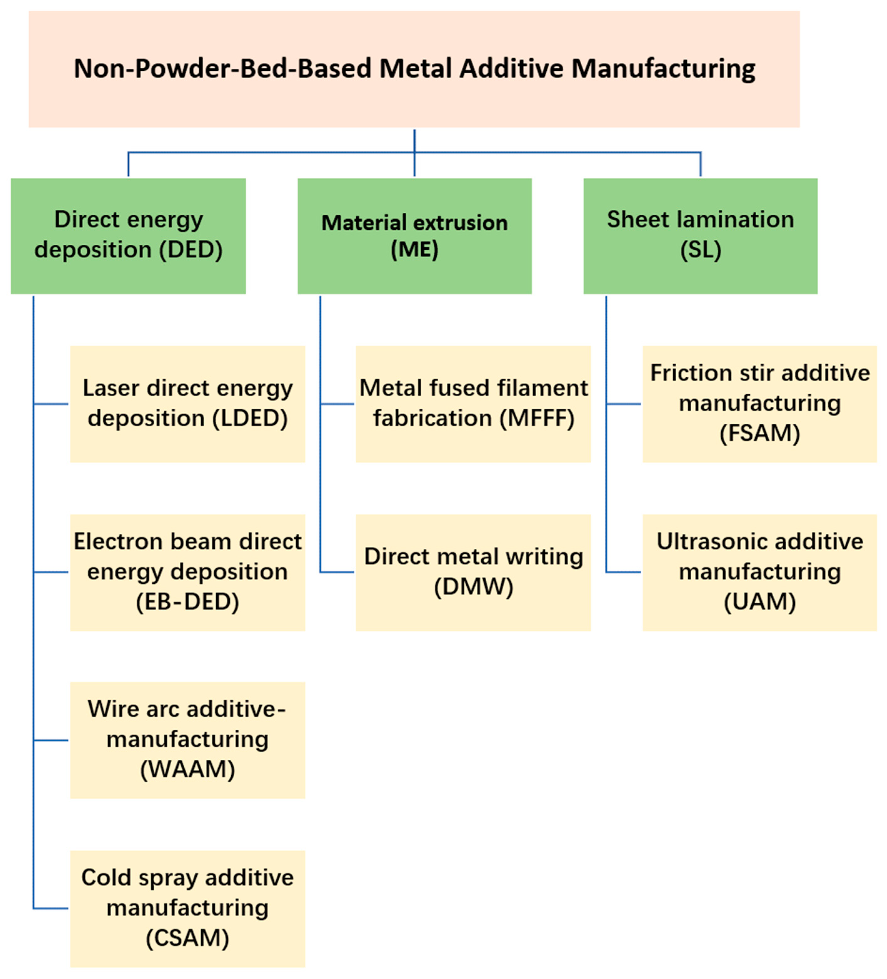
2. Classification of Non-Powder-Bed-Based MAM
3. Direct Energy Deposition
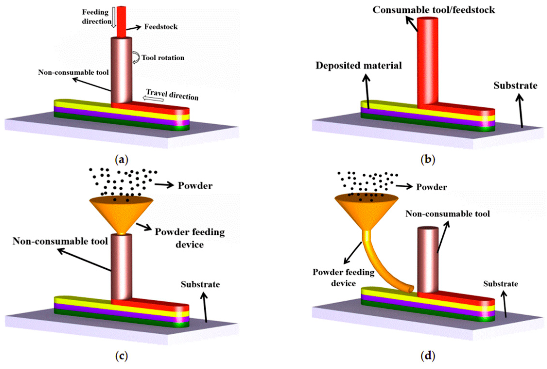
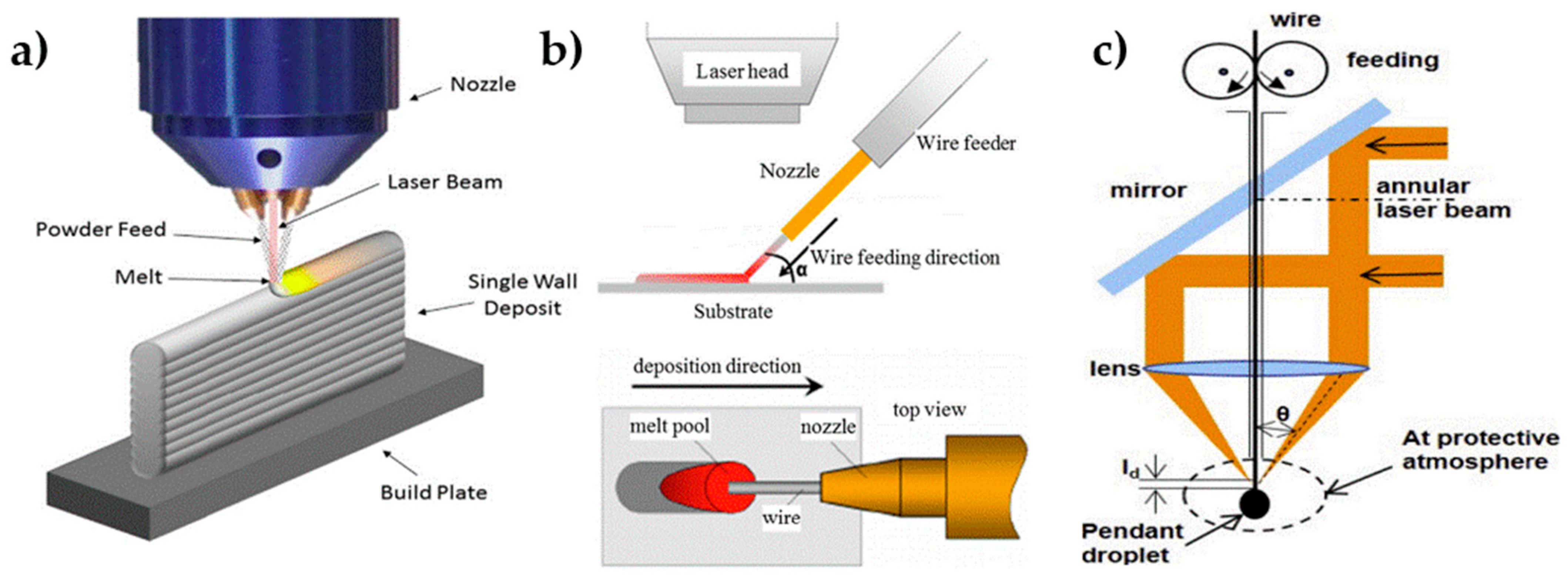
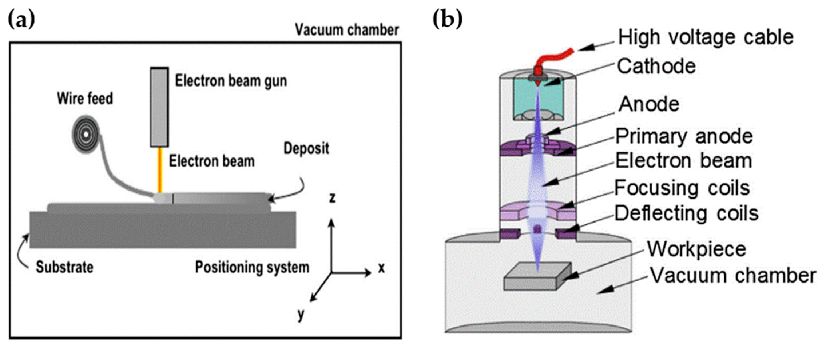
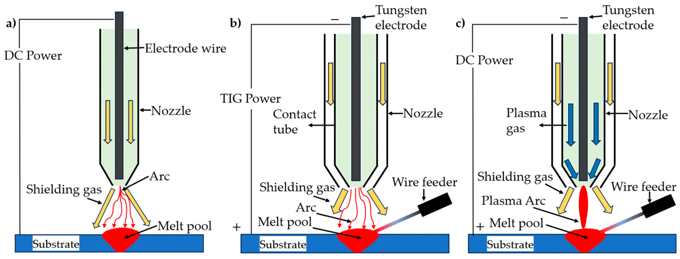
3.1. Method and Mechanism
3.2. Materials, Mechanical Properties, and Defects of DED: The State of the Art
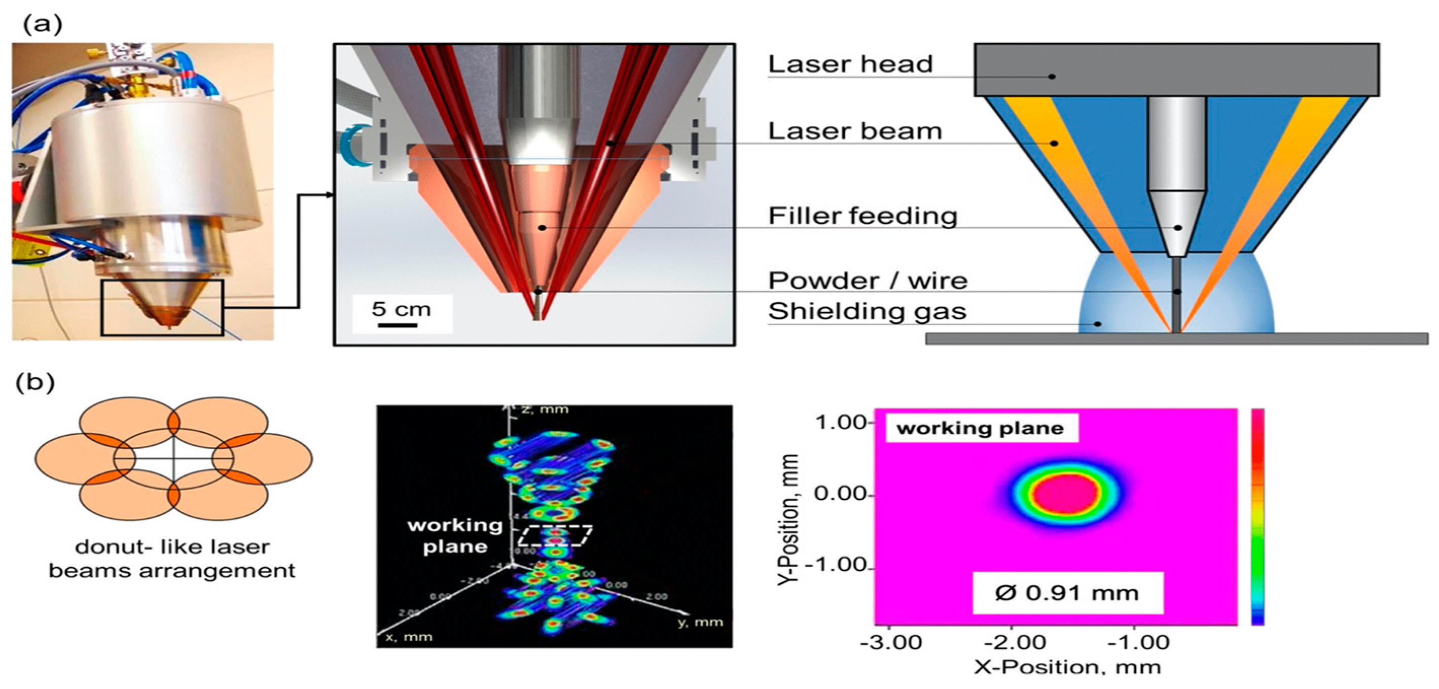
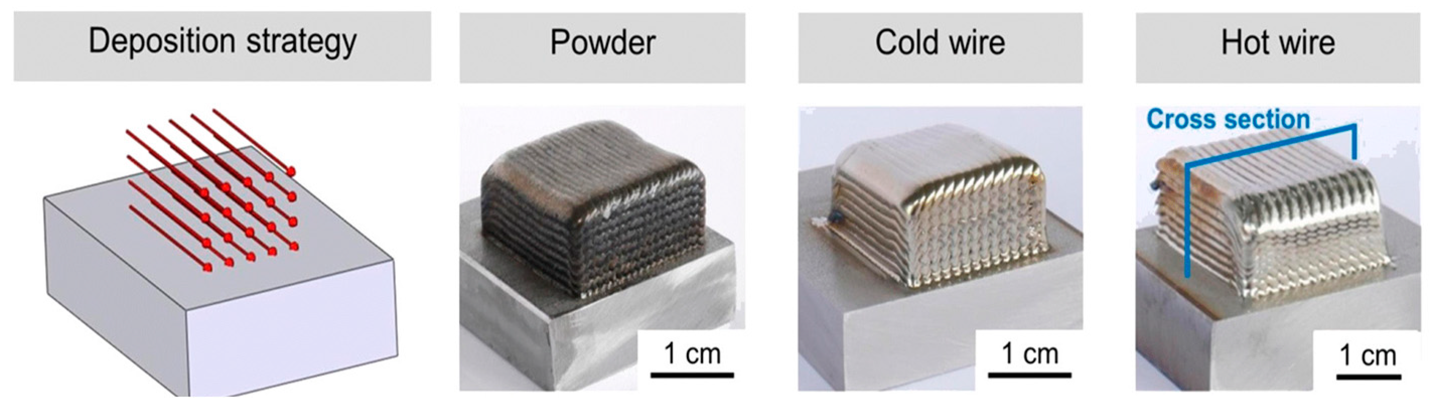
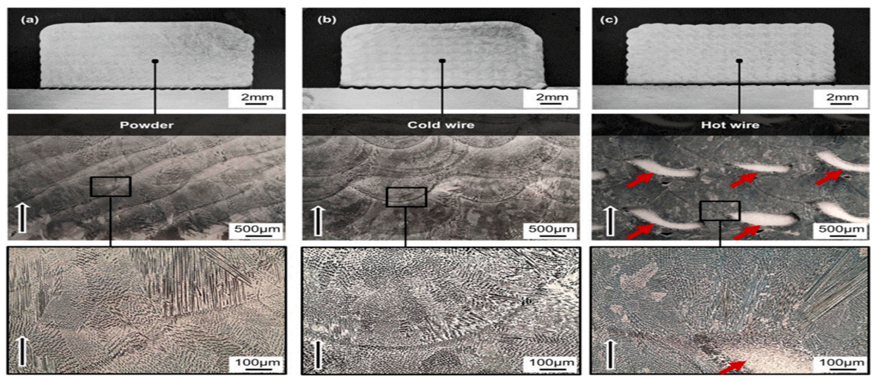
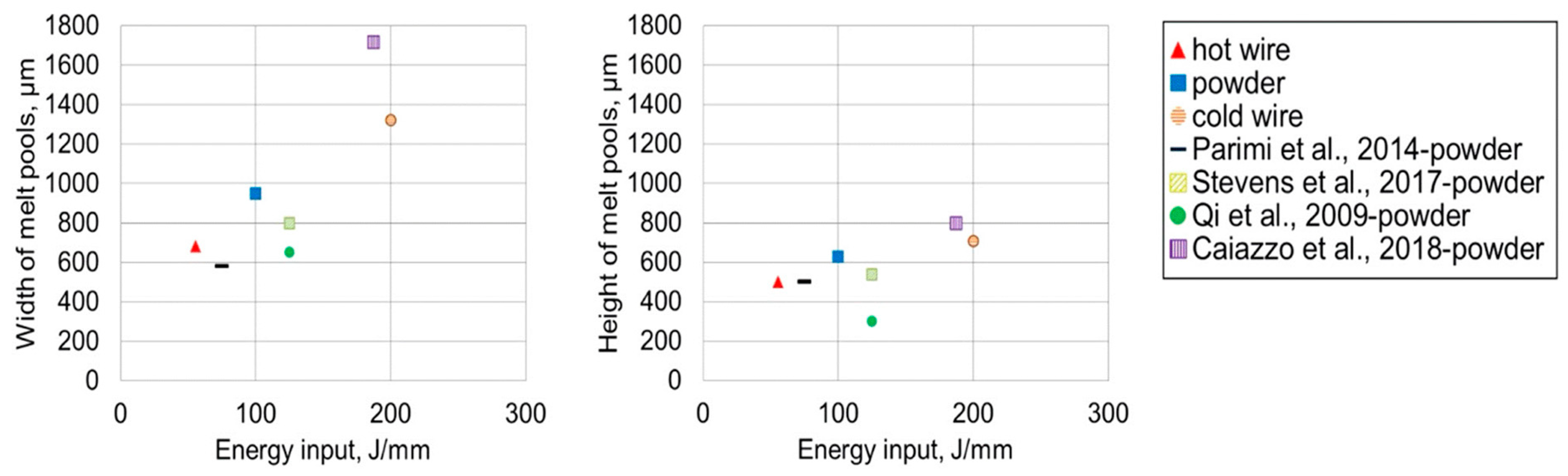
3.3. Six-Beam Direct-Diode LDED
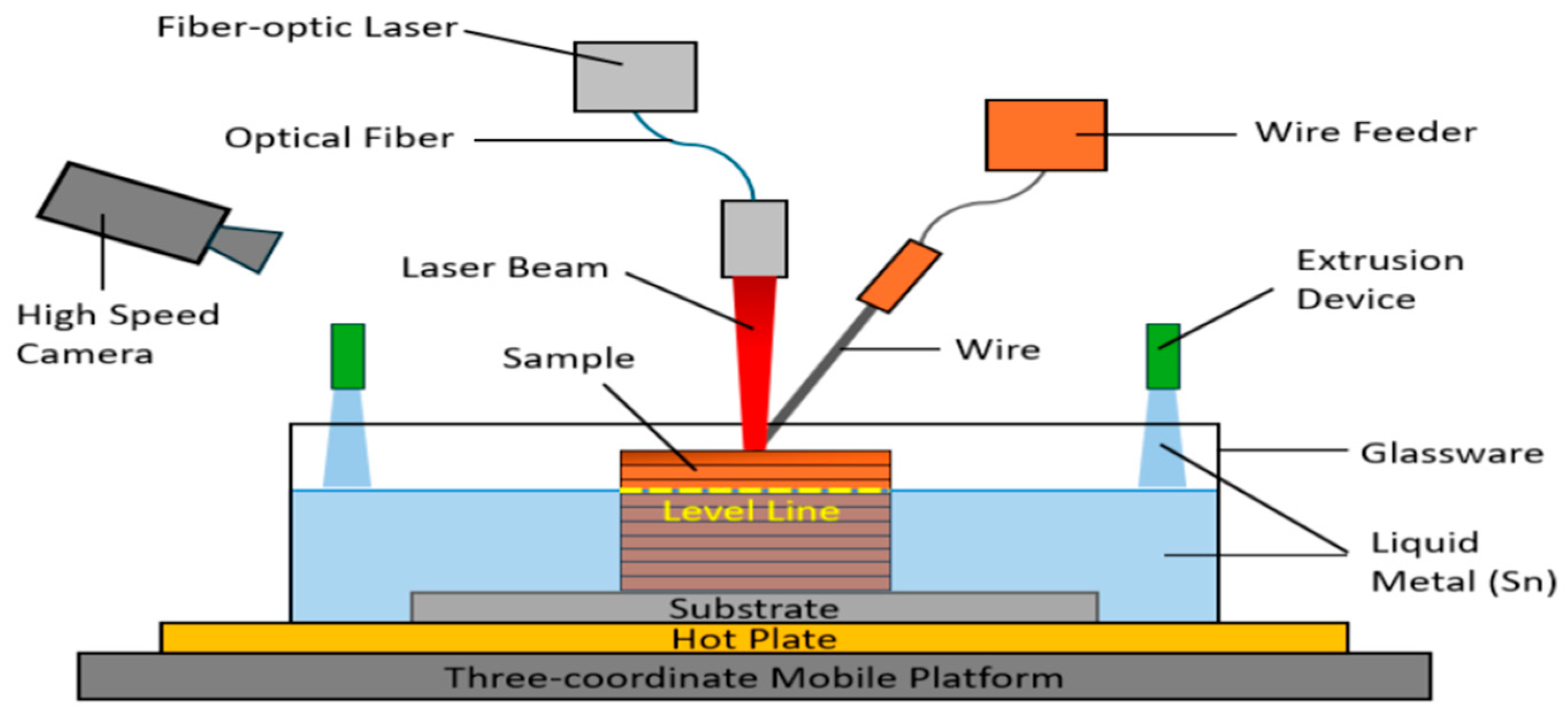
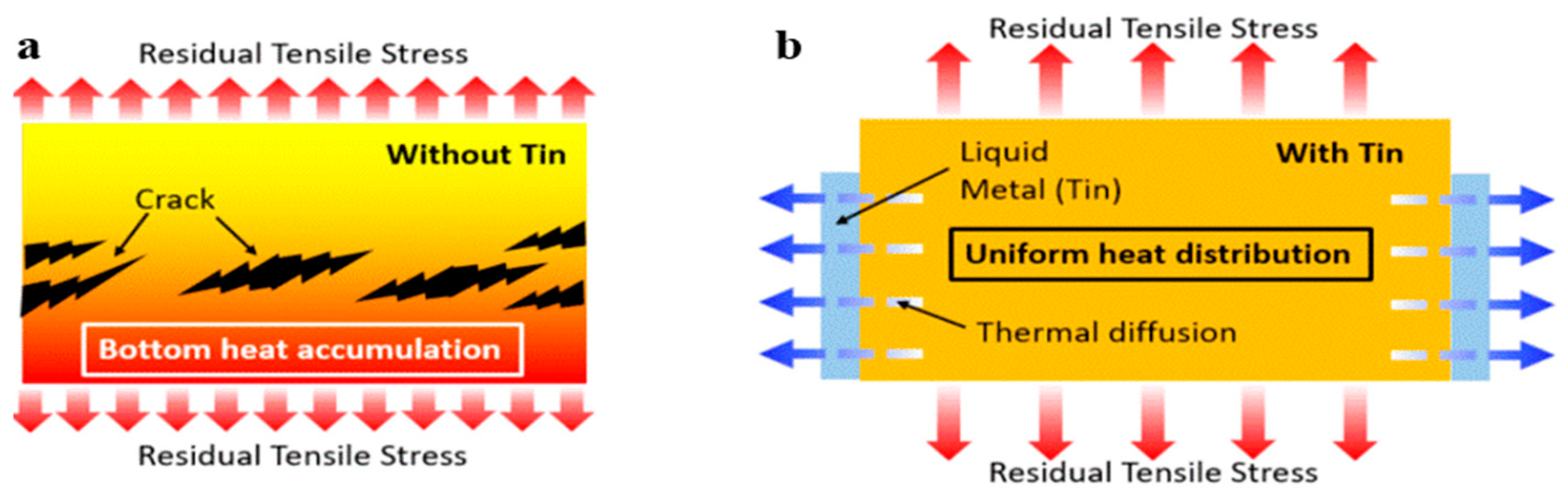
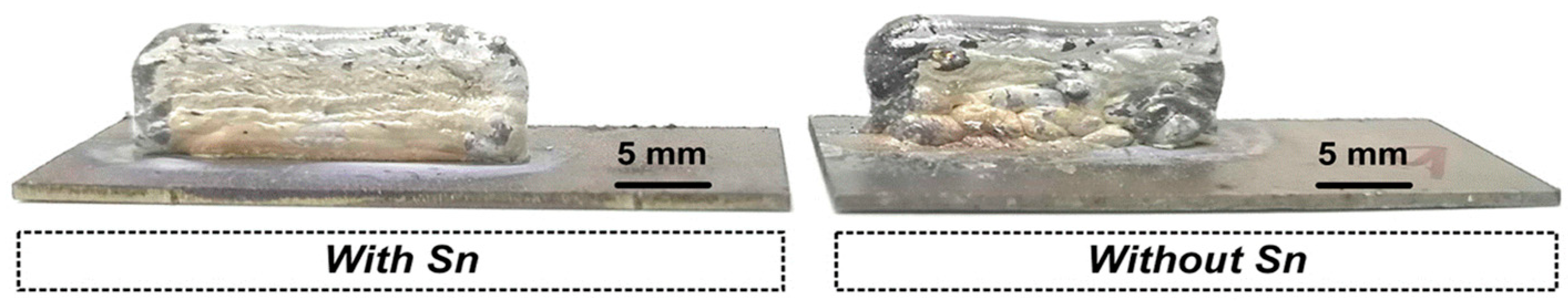
3.4. Liquid-Metal-Assisted DED
3.5. Hot-Forge WAAM
4. Material Extrusion
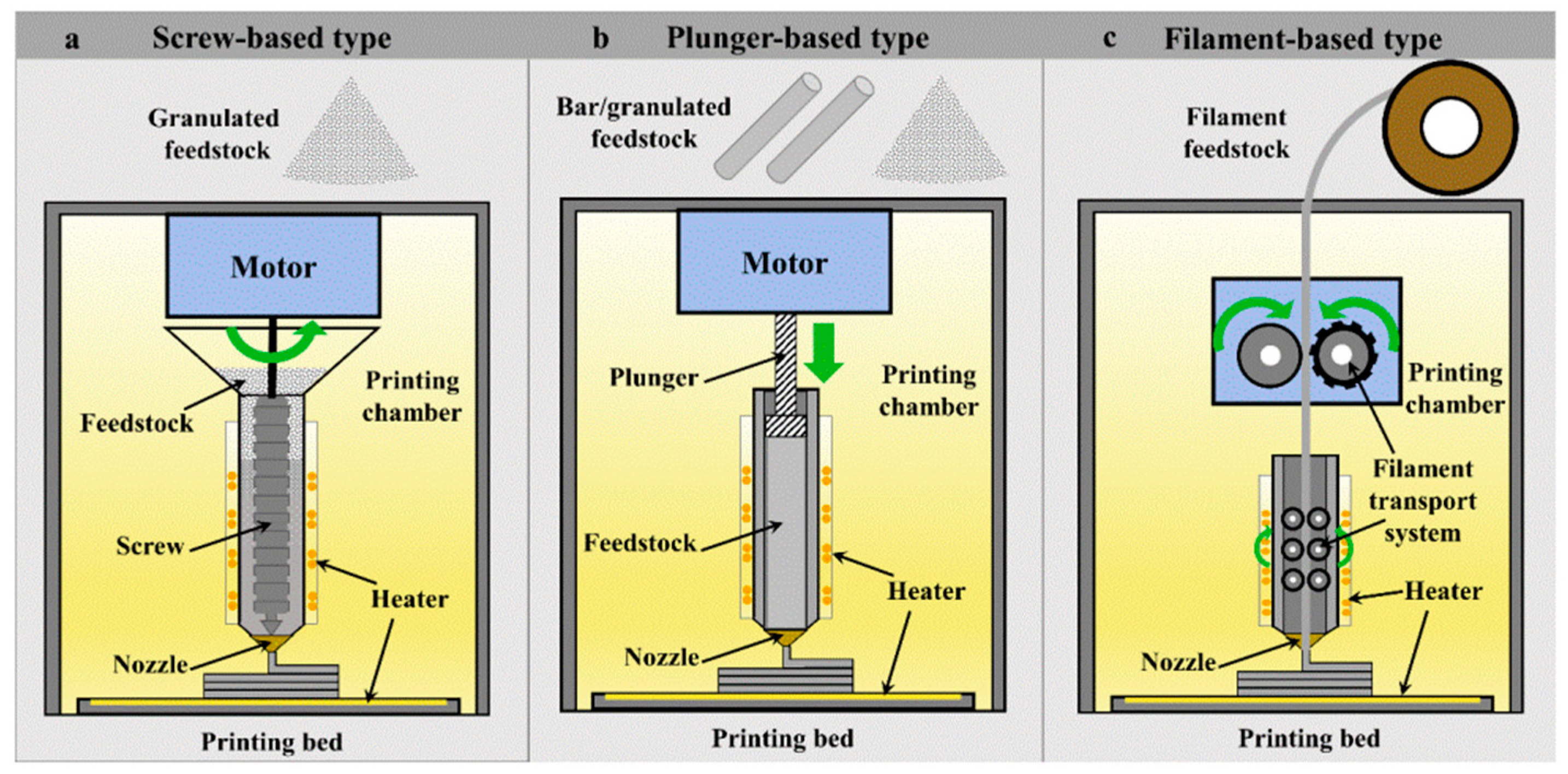
4.1. Method and Mechanism
4.2. Materials, Mechanical Properties, and Defects of ME: The State of the Art
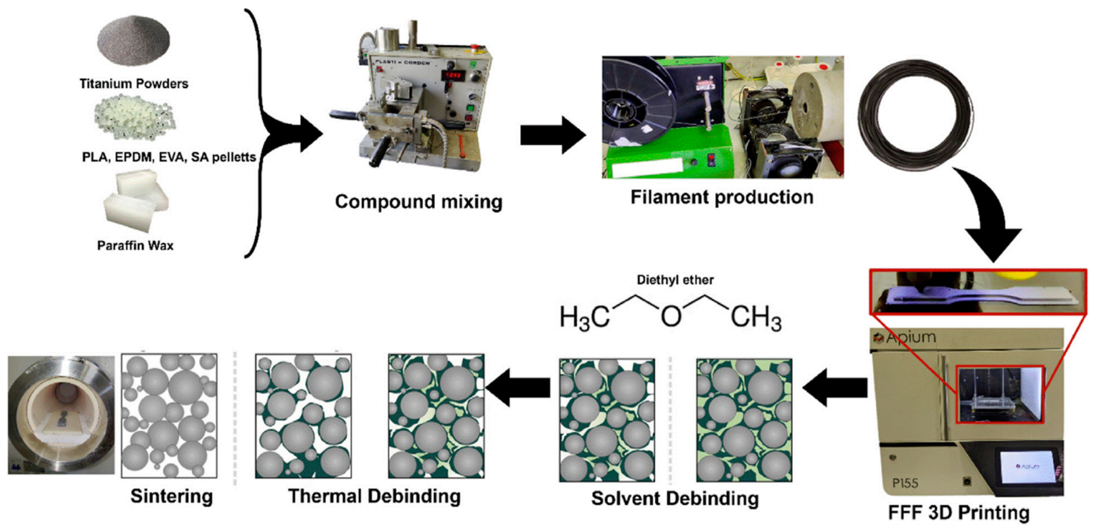
4.3. Bio-Based MFFF
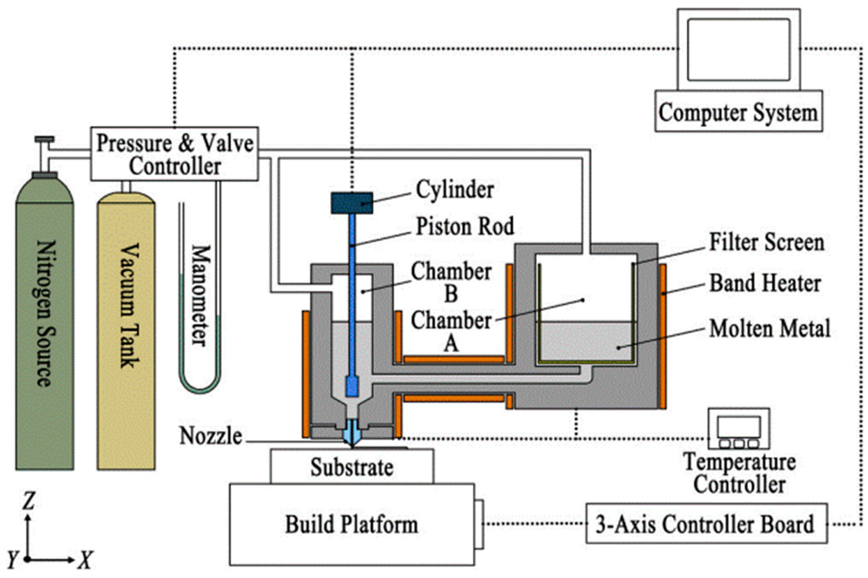
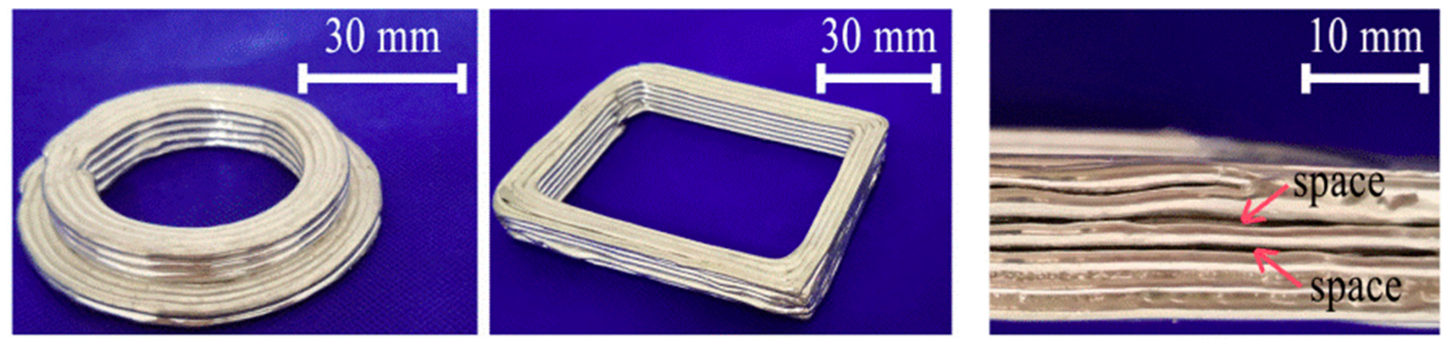
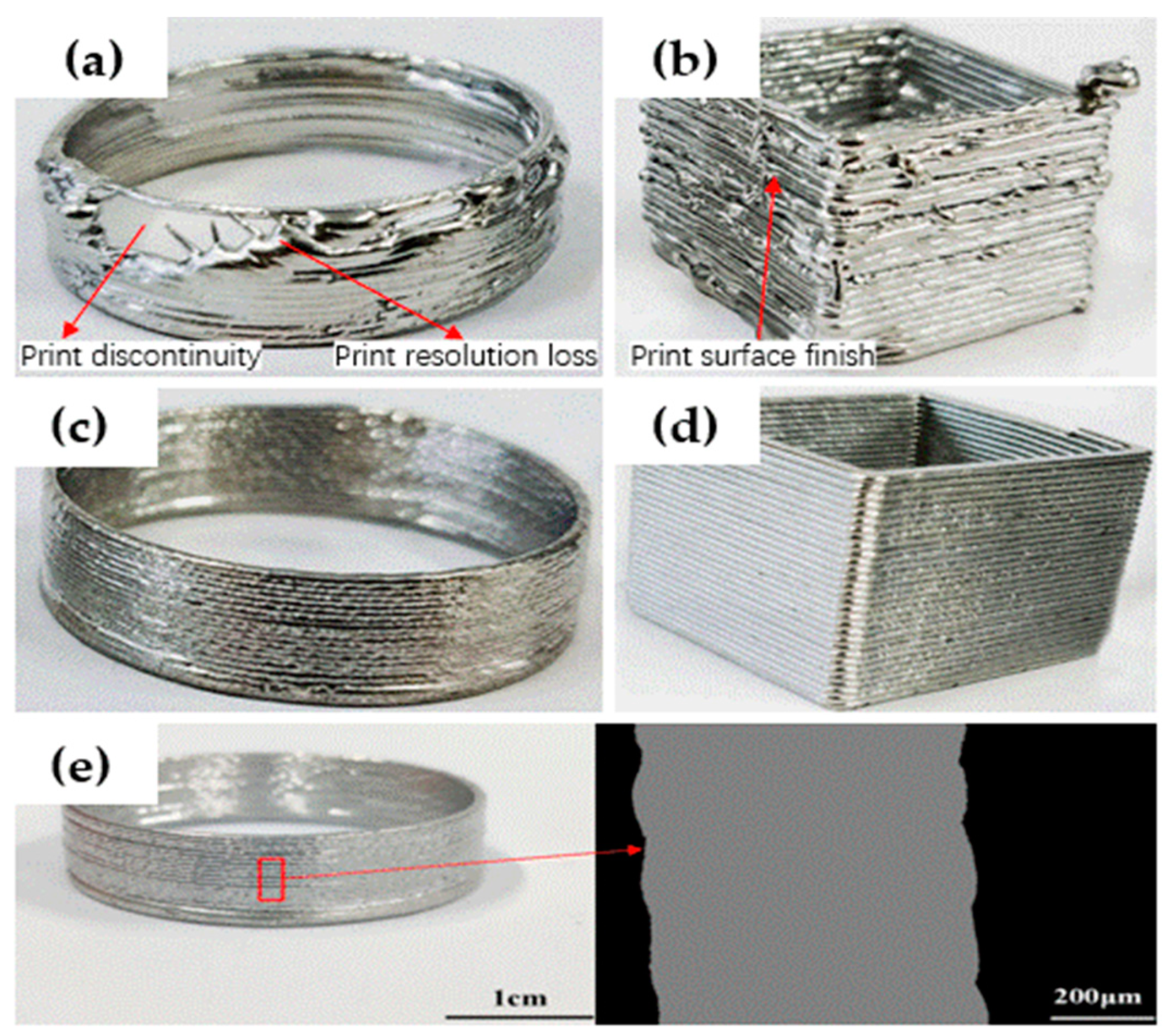
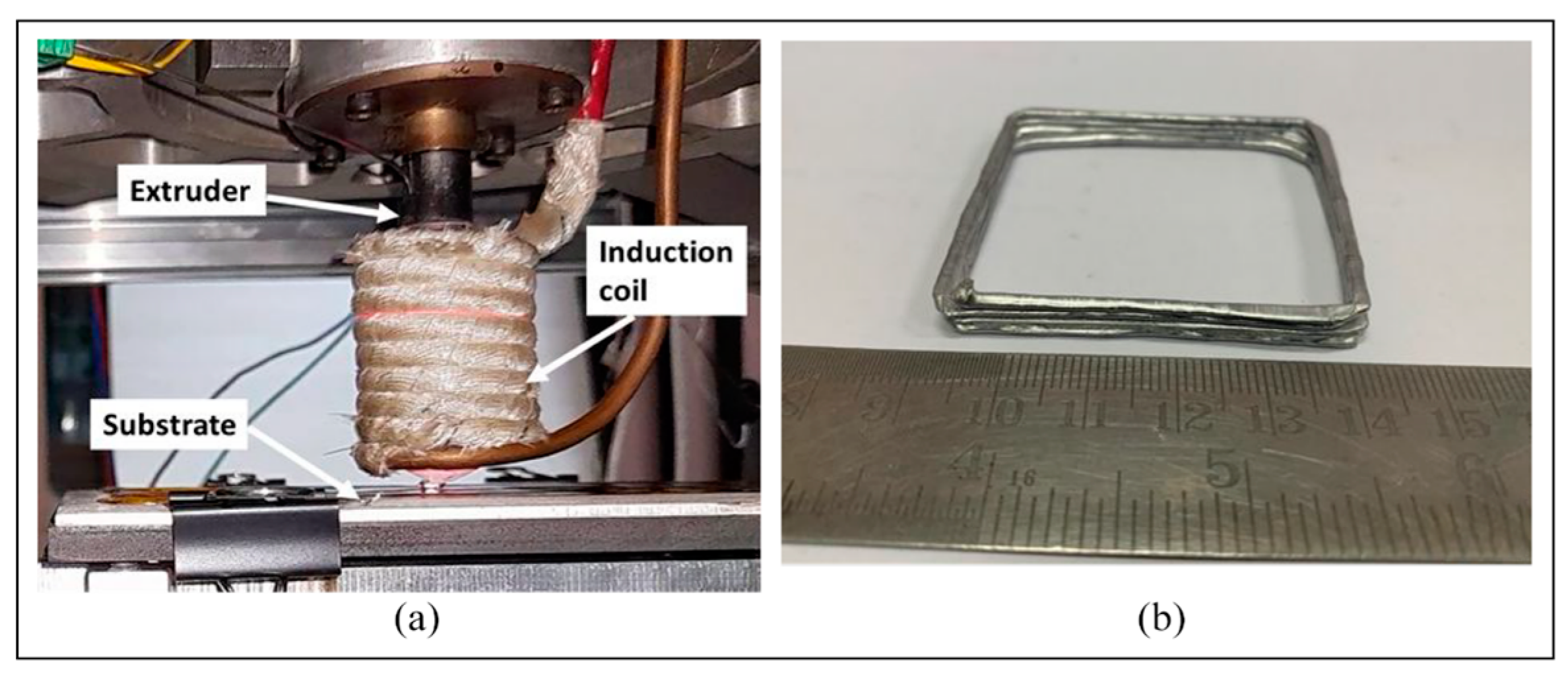
4.4. Thixotropic ME
5. Sheet Lamination
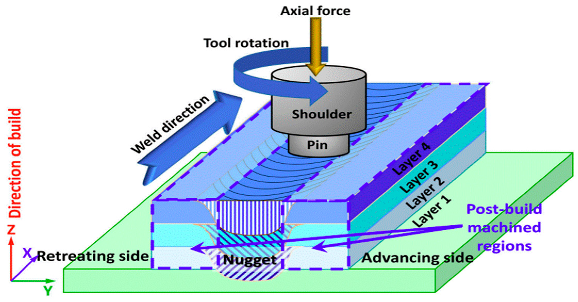
5.1. Method and Mechanism
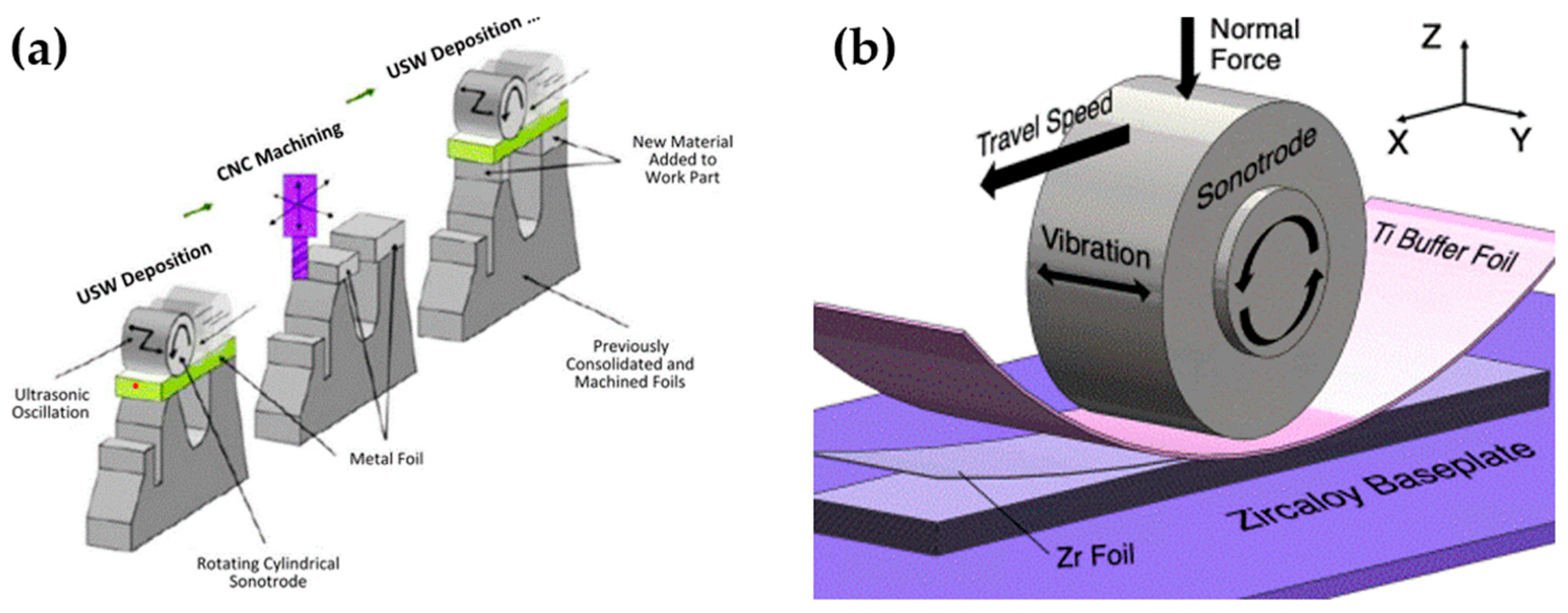
5.2. Materials, Mechanical Properties, and Defects of SL: The State of the Art
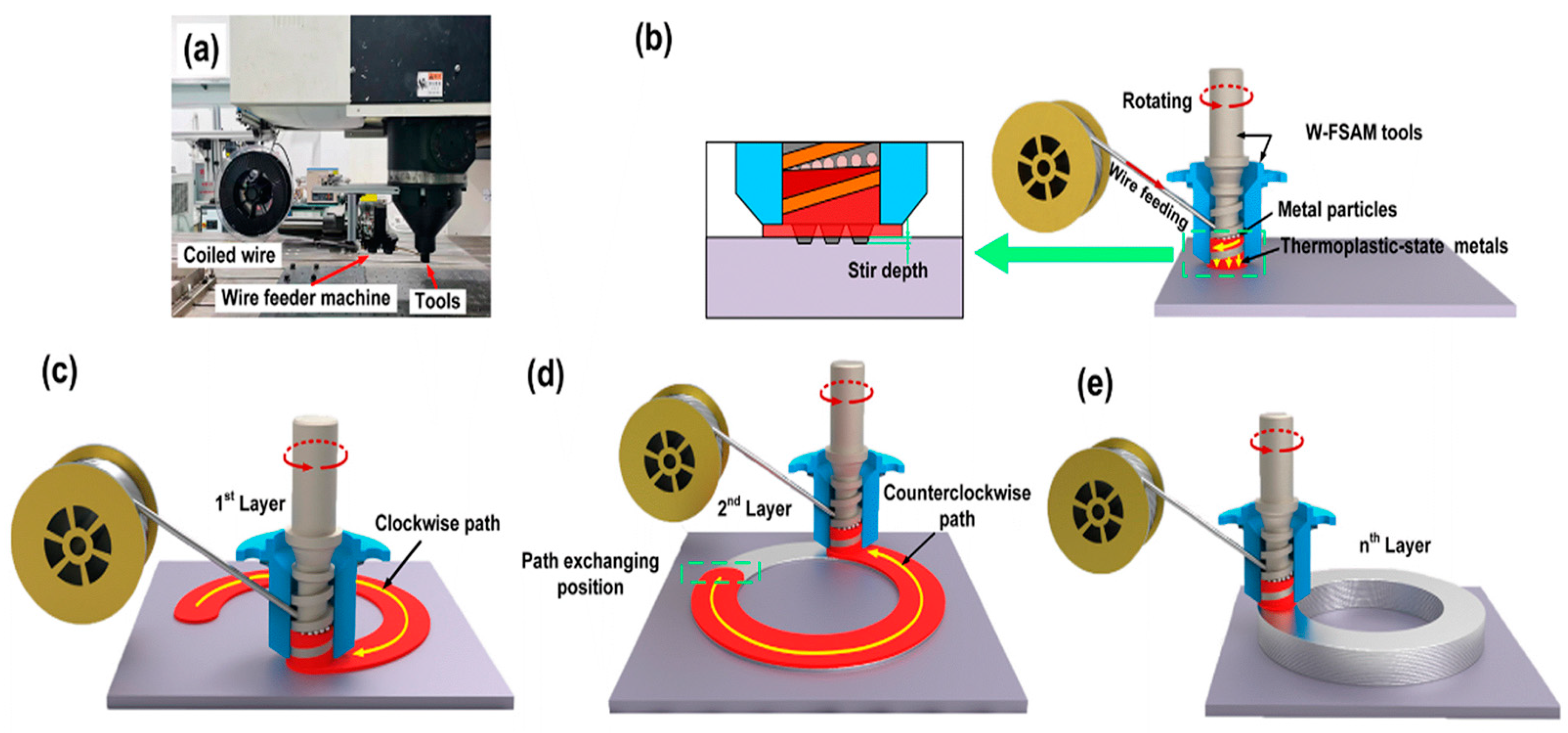
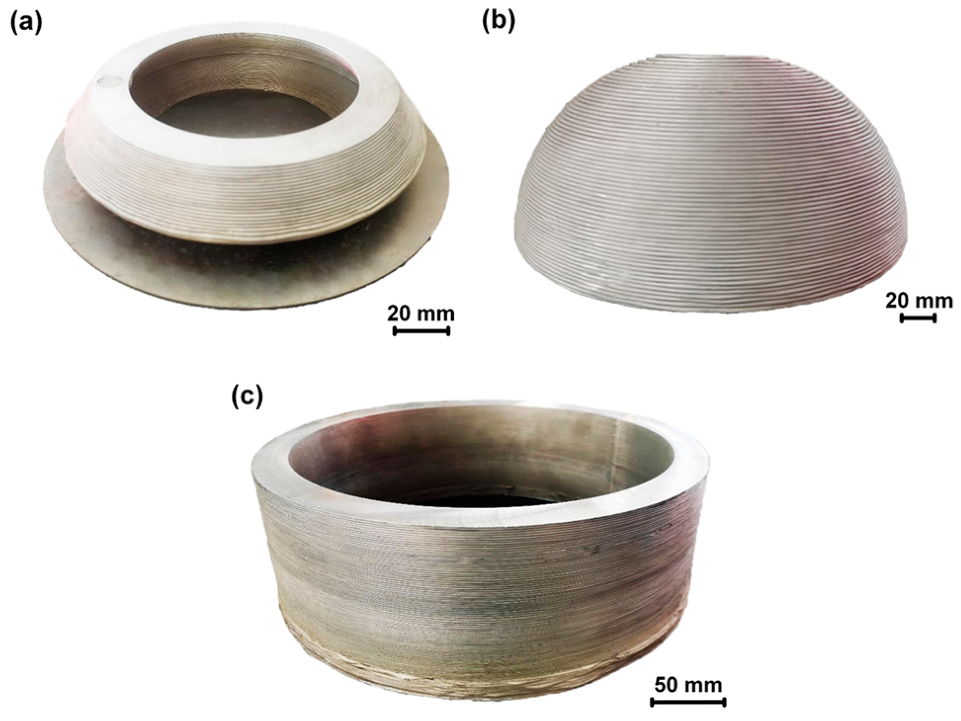
5.3. Wire-Based FSAM
6. Conclusions
Funding
Conflicts of Interest
Abbreviations
| MAM | Metal additive manufacturing |
| PBF | Powder bed fusion |
| BJ | Binder jetting |
| DED | Direct energy deposition |
| ME | Material extrusion |
| SL | Sheet lamination |
| LDED | Laser direct energy deposition |
| EB-DED | Electron beam direct energy deposition |
| WAAM | Wire-arc additive manufacturing |
| CSAM | Cold spray additive manufacturing |
| SR | Surface roughness |
| Ra | Roughness average |
| MIG | Metal inert gas welding |
| PAW | Plasma arc welding |
| TIG | Tungsten inert gas welding |
| YS | Yield stress |
| UTS | Ultimate tensile strength |
| MFFF | Metal fused-filament fabrication |
| EM | Extrusion multiplier |
| FFF | Fused-filament fabrication |
| DMW | Direct metal writing |
| FSAM | Friction stir additive manufacturing |
| UAM | Ultrasonic additive manufacturing |
| HIP | Hot isostatic pressing |
| PLA | Polylactic acid |
| IH | Induction heating |
| CNC | Computer numerical control |
| AFSD | Additive friction stir deposition |
References
- Grand View Research, G.v.r. Metal 3D Printing Market Size & Trends Analysis Report. 2020. Available online: https://www.grandviewresearch.com/industry-analysis/metal-3d-printing-market (accessed on 22 December 2023).
- ISO/ASTM 52900(en); Additive Manufacturing—General Principles—Terminology. Available online: https://www.iso.org/obp/ui/#iso:std:iso-astm:52900:dis:ed-2:v1:en (accessed on 7 May 2024).
- Vafadar, A.; Guzzomi, F.; Rassau, A.; Hayward, K. Advances in metal additive manufacturing: A review of common processes, industrial applications, and current challenges. Appl. Sci. 2021, 11, 1213. [Google Scholar] [CrossRef]
- Wohlers, T. Wohlers Report 2017: 3D Printing and Additive Manufacturing State of the Industry: Annual Worldwide Progress Report; Wohlers Associates: Fort Collins, CO, USA, 2014. [Google Scholar]
- Jiménez, A.; Bidare, P.; Hassanin, H.; Tarlochan, F.; Dimov, S.; Essa, K. Powder-based laser hybrid additive manufacturing of metals: A review. Int. J. Adv. Manuf. Technol. 2021, 114, 63–96. [Google Scholar] [CrossRef]
- Goodwin, A. Porsche Tests 3D-Printed Pistons for Its 911 GT2 RS. Available online: https://www.cnet.com/roadshow/news/porsche-tests-3d-printed-pistons-for-911-gt2-rs/ (accessed on 22 December 2023).
- Heinl, P.; Rottmair, A.; Körner, C.; Singer, R.F. Cellular titanium by selective electron beam melting. Adv. Eng. Mater. 2007, 9, 360–364. [Google Scholar] [CrossRef]
- Aboulkhair, N.T.; Simonelli, M.; Parry, L.; Ashcroft, I.; Tuck, C.; Hague, R. 3D printing of Aluminium alloys: Additive Manufacturing of Aluminium alloys using selective laser melting. Prog. Mater. Sci. 2019, 106, 100578. [Google Scholar] [CrossRef]
- Yin, Y.; Tan, Q.; Bermingham, M.; Mo, N.; Zhang, J.; Zhang, M.-X. Laser additive manufacturing of steels. Int. Mater. Rev. 2022, 67, 487–573. [Google Scholar] [CrossRef]
- Qu, S.; Ding, J.; Fu, J.; Fu, M.; Zhang, B.; Song, X. High-precision laser powder bed fusion processing of pure copper. Addit. Manuf. 2021, 48, 102417. [Google Scholar] [CrossRef]
- Han, X.; Zhu, H.; Nie, X.; Wang, G.; Zeng, X. Investigation on selective laser melting AlSi10Mg cellular lattice strut: Molten pool morphology, surface roughness and dimensional accuracy. Materials 2018, 11, 392. [Google Scholar] [CrossRef]
- Bosio, F.; Shen, H.; Liu, Y.; Lombardi, M.; Rometsch, P.; Wu, X.; Zhu, Y.; Huang, A. Production strategy for manufacturing large-scale AlSi10Mg components by laser powder bed fusion. JOM 2021, 73, 770–780. [Google Scholar] [CrossRef]
- Dutta, B.; Froes, F.S. The additive manufacturing (AM) of titanium alloys. Met. Powder Rep. 2017, 72, 96–106. [Google Scholar] [CrossRef]
- Javaid, M.; Haleem, A.; Singh, R.P.; Suman, R. 3D printing applications for healthcare research and development. Glob. Health J. 2022, 6, 217–226. [Google Scholar] [CrossRef]
- Renderos, M.; Girot, F.; Lamikiz, A.; Torregaray, A.; Saintier, N. Ni based powder reconditioning and reuse for LMD process. Phys. Procedia 2016, 83, 769–777. [Google Scholar] [CrossRef]
- Vock, S.; Klöden, B.; Kirchner, A.; Weißgärber, T.; Kieback, B. Powders for powder bed fusion: A review. Prog. Addit. Manuf. 2019, 4, 383–397. [Google Scholar] [CrossRef]
- Sousa, M.; Arezes, P.; Silva, F. Nanomaterials exposure as an occupational risk in metal additive manufacturing. J. Phys. Conf. Ser. 2019, 1323, 012013. [Google Scholar] [CrossRef]
- Chen, R.; Yin, H.; Cole, I.S.; Shen, S.; Zhou, X.; Wang, Y.; Tang, S. Exposure, assessment and health hazards of particulate matter in metal additive manufacturing: A review. Chemosphere 2020, 259, 127452. [Google Scholar] [CrossRef]
- Dawes, J.; Bowerman, R.; Trepleton, R. Introduction to the additive manufacturing powder metallurgy supply chain. Johns. Matthey Technol. Rev. 2015, 59, 243–256. [Google Scholar] [CrossRef]
- Ceccanti, F.; Giorgetti, A.; Arcidiacono, G.; Citti, P. Laser powder bed fusion: A review on the design constraints. IOP Conf. Ser. Mater. Sci. Eng. 2021, 1038, 012065. [Google Scholar] [CrossRef]
- Zhang, Y.; Bai, S.; Riede, M.; Garratt, E.; Roch, A. A comprehensive study on fused filament fabrication of Ti-6Al-4V structures. Addit. Manuf. 2020, 34, 101256. [Google Scholar] [CrossRef]
- Liu, T.-S.; Chen, P.; Qiu, F.; Yang, H.-Y.; Jin, N.T.Y.; Chew, Y.; Wang, D.; Li, R.; Jiang, Q.-C.; Tan, C. Review on laser directed energy deposited aluminum alloys. Int. J. Extrem. Manuf. 2024, 6, 022004. [Google Scholar] [CrossRef]
- Zhang, W.; Xu, C.; Li, C.; Wu, S. Advances in Ultrasonic-Assisted Directed Energy Deposition (DED) for Metal Additive Manufacturing. Crystals 2024, 14, 114. [Google Scholar] [CrossRef]
- Srivastava, M.; Rathee, S.; Tiwari, A.; Dongre, M. Wire arc additive manufacturing of metals: A review on processes, materials and their behaviour. Mater. Chem. Phys. 2023, 294, 126988. [Google Scholar] [CrossRef]
- Obiko, J.; Kachomba, T.; Mutua, J.; Ngoret, J.; Jeje, S.; Shongwe, M.; Malatji, N. A brief review on industrial remanufacturing of structural and functional components: Wire-Arc Additive Manufacturing Technique. Eng. Solid Mech. 2024, 12, 363–386. [Google Scholar] [CrossRef]
- Yin, S.; Fan, N.; Huang, C.; Xie, Y.; Zhang, C.; Lupoi, R.; Li, W. Towards high-strength cold spray additive manufactured metals: Methods, mechanisms, and properties. J. Mater. Sci. Technol. 2024, 170, 47–64. [Google Scholar] [CrossRef]
- Sadaf, M.; Bragaglia, M.; Slemenik Perše, L.; Nanni, F. Advancements in metal additive manufacturing: A comprehensive review of material extrusion with highly filled polymers. J. Manuf. Mater. Process. 2024, 8, 14. [Google Scholar] [CrossRef]
- Bankapalli, N.K.; Gupta, V.; Saxena, P.; Bajpai, A.; Lahoda, C.; Polte, J. Filament fabrication and subsequent additive manufacturing, debinding, and sintering for extrusion-based metal additive manufacturing and their applications: A review. Compos. Part B Eng. 2023, 264, 110915. [Google Scholar] [CrossRef]
- Chen, B.; Wang, T.; Xi, X.; Tan, C.; Song, X. Additive manufacturing of Ti-Al functionally graded material by laser based directed energy deposition. Rapid Prototyp. J. 2023, 29, 558–568. [Google Scholar] [CrossRef]
- Tarasov, S.Y.; Filippov, A.; Shamarin, N.; Fortuna, S.; Maier, G.; Kolubaev, E. Microstructural evolution and chemical corrosion of electron beam wire-feed additively manufactured AISI 304 stainless steel. J. Alloys Compd. 2019, 803, 364–370. [Google Scholar] [CrossRef]
- Gibson, I.; Rosen, D.; Stucker, B.; Khorasani, M.; Gibson, I.; Rosen, D.; Stucker, B.; Khorasani, M. Sheet lamination. In Additive Manufacturing Technologies; Springer: Cham, Switzerland, 2021; pp. 253–283. [Google Scholar]
- Tebianian, M.; Aghaie, S.; Razavi Jafari, N.S.; Elmi Hosseini, S.R.; Pereira, A.B.; Fernandes, F.A.; Farbakhti, M.; Chen, C.; Huo, Y. A Review of the Metal Additive Manufacturing Processes. Materials 2023, 16, 7514. [Google Scholar] [CrossRef]
- Gonzalez-Gutierrez, J.; Cano, S.; Schuschnigg, S.; Kukla, C.; Sapkota, J.; Holzer, C. Additive manufacturing of metallic and ceramic components by the material extrusion of highly-filled polymers: A review and future perspectives. Materials 2018, 11, 840. [Google Scholar] [CrossRef] [PubMed]
- Alkindi, T.; Alyammahi, M.; Susantyoko, R.A.; Atatreh, S. The effect of varying specimens’ printing angles to the bed surface on the tensile strength of 3D-printed 17-4PH stainless-steels via metal FFF additive manufacturing. MRS Commun. 2021, 11, 310–316. [Google Scholar] [CrossRef]
- Oh, W.J.; Son, Y.; Shim, D.S. Effect of in-situ post heating on repairing STS316L built by laser powder bed fusion using direct energy deposition. Korean J. Met. Mater. 2019, 57, 543–553. [Google Scholar] [CrossRef]
- Careri, F.; Imbrogno, S.; Umbrello, D.; Attallah, M.M.; Outeiro, J.; Batista, A.C. Machining and heat treatment as post-processing strategies for Ni-superalloys structures fabricated using direct energy deposition. J. Manuf. Process. 2021, 61, 236–244. [Google Scholar] [CrossRef]
- Jandyal, A.; Chaturvedi, I.; Wazir, I.; Raina, A.; Haq, M.I.U. 3D printing—A review of processes, materials and applications in industry 4.0. Sustain. Oper. Comput. 2022, 3, 33–42. [Google Scholar] [CrossRef]
- Yao, X.; Ge, P.; Li, J.; Wang, Y.; Li, T.; Liu, W.; Zhang, Z. Controlling the solidification process parameters of direct energy deposition additive manufacturing considering laser and powder properties. Comput. Mater. Sci. 2020, 182, 109788. [Google Scholar] [CrossRef]
- Singh, P.; Balla, V.K.; Gokce, A.; Atre, S.V.; Kate, K.H. Additive manufacturing of Ti-6Al-4V alloy by metal fused filament fabrication (MF 3): Producing parts comparable to that of metal injection molding. Prog. Addit. Manuf. 2021, 6, 593–606. [Google Scholar] [CrossRef]
- Zhang, Y.; Wu, L.; Guo, X.; Kane, S.; Deng, Y.; Jung, Y.-G.; Lee, J.-H.; Zhang, J. Additive manufacturing of metallic materials: A review. J. Mater. Eng. Perform. 2018, 27, 1–13. [Google Scholar] [CrossRef]
- Haddad, M.; Nixon, K.B.; Wolff, S. Sheet Lamination. In Springer Handbook of Additive Manufacturing; Springer: Cham, Switzerland, 2023; pp. 407–423. [Google Scholar]
- Bambach, M.; Sizova, I.; Kies, F.; Haase, C. Directed energy deposition of Inconel 718 powder, cold and hot wire using a six-beam direct diode laser set-up. Addit. Manuf. 2021, 47, 102269. [Google Scholar] [CrossRef]
- Caiazzo, F. Laser-aided Directed Metal Deposition of Ni-based superalloy powder. Opt. Laser Technol. 2018, 103, 193–198. [Google Scholar] [CrossRef]
- Parimi, L.L.; Attallah, M.M.; Gebelin, J.-C.; Reed, R.C. Direct laser fabrication of Inconel-718: Effects on distortion and microstructure. Proc. Superalloys 2012, 12, 1–9. [Google Scholar]
- Nurhudan, A.I.; Supriadi, S.; Whulanza, Y.; Saragih, A.S. Additive manufacturing of metallic based on extrusion process: A review. J. Manuf. Process. 2021, 66, 228–237. [Google Scholar] [CrossRef]
- Strano, M.; Rane, K.; Farid, M.A.; Mussi, V.; Zaragoza, V.; Monno, M. Extrusion-based additive manufacturing of forming and molding tools. Int. J. Adv. Manuf. Technol. 2021, 117, 2059–2071. [Google Scholar] [CrossRef]
- Matsuzaki, R.; Kanatani, T.; Todoroki, A. Multi-material additive manufacturing of polymers and metals using fused filament fabrication and electroforming. Addit. Manuf. 2019, 29, 100812. [Google Scholar] [CrossRef]
- Mousapour, M.; Salmi, M.; Klemettinen, L.; Partanen, J. Feasibility study of producing multi-metal parts by Fused Filament Fabrication (FFF) technique. J. Manuf. Process. 2021, 67, 438–446. [Google Scholar] [CrossRef]
- Bhatt, P.M.; Kabir, A.M.; Peralta, M.; Bruck, H.A.; Gupta, S.K. A robotic cell for performing sheet lamination-based additive manufacturing. Addit. Manuf. 2019, 27, 278–289. [Google Scholar] [CrossRef]
- Ehmsen, S.; Glatt, M.; Aurich, J.C. Influence of process parameters on the power consumption of high-speed laser directed energy deposition. Procedia CIRP 2023, 116, 89–94. [Google Scholar] [CrossRef]
- Sæterbø, M.; Solvang, W.D. Evaluating the cost competitiveness of metal additive manufacturing—A case study with metal material extrusion. CIRP J. Manuf. Sci. Technol. 2023, 45, 113–124. [Google Scholar] [CrossRef]
- Chen, H.; Meng, X.; Chen, J.; Xie, Y.; Wang, J.; Sun, S.; Zhao, Y.; Li, J.; Wan, L.; Huang, Y. Wire-based friction stir additive manufacturing. Addit. Manuf. 2023, 70, 103557. [Google Scholar] [CrossRef]
- Sreekanth, S.; Ghassemali, E.; Hurtig, K.; Joshi, S.; Andersson, J. Effect of direct energy deposition process parameters on single-track deposits of alloy 718. Metals 2020, 10, 96. [Google Scholar] [CrossRef]
- Sampson, R.; Lancaster, R.; Sutcliffe, M.; Carswell, D.; Hauser, C.; Barras, J. The influence of key process parameters on melt pool geometry in direct energy deposition additive manufacturing systems. Opt. Laser Technol. 2021, 134, 106609. [Google Scholar] [CrossRef]
- Chaurasia, J.K.; Jinoop, A.; Paul, C.; Bindra, K.; Balla, V.K.; Bontha, S. Effect of deposition strategy and post processing on microstructure and mechanical properties of serviced Inconel 625 parts repaired using laser directed energy deposition. Opt. Laser Technol. 2024, 168, 109831. [Google Scholar] [CrossRef]
- Lieberwirth, C.; Harder, A.; Seitz, H. Extrusion based additive manufacturing of metal parts. J. Mech. Eng. Autom 2017, 7, 79–83. [Google Scholar]
- Rane, K.; Strano, M. A comprehensive review of extrusion-based additive manufacturing processes for rapid production of metallic and ceramic parts. Adv. Manuf. 2019, 7, 155–173. [Google Scholar] [CrossRef]
- Miclette, O.; Côté, R.; Demers, V.; Brailovski, V. Material extrusion additive manufacturing of low-viscosity metallic feedstocks: Performances of the plunger-based approach. Addit. Manuf. 2022, 60, 103252. [Google Scholar] [CrossRef]
- Hang, Z.Y.; Jones, M.E.; Brady, G.W.; Griffiths, R.J.; Garcia, D.; Rauch, H.A.; Cox, C.D.; Hardwick, N. Non-beam-based metal additive manufacturing enabled by additive friction stir deposition. Scr. Mater. 2018, 153, 122–130. [Google Scholar]
- Xometry. Selecting Right Surface Roughness for CNC Machining. Available online: https://xometry.pro/en/articles/cnc-machining-surface-roughness/ (accessed on 22 December 2023).
- Khanna, N.; Salvi, H.; Karaş, B.; Fairoz, I.; Shokrani, A. Cost Modelling for Powder Bed Fusion and Directed Energy Deposition Additive Manufacturing. J. Manuf. Mater. Process. 2024, 8, 142. [Google Scholar] [CrossRef]
- Kalami, H.; Urbanic, J. Exploration of surface roughness measurement solutions for additive manufactured components built by multi-axis tool paths. Addit. Manuf. 2021, 38, 101822. [Google Scholar] [CrossRef]
- Mao, Y.; Chen, H.; Xiong, J. Microstructural characteristics and mechanical properties of Al-Cu alloys fabricated via 8-shaped oscillating laser wire additive manufacturing. Mater. Sci. Eng. A 2024, 914, 147101. [Google Scholar] [CrossRef]
- Singh, G.; Missiaen, J.-M.; Bouvard, D.; Chaix, J.-M. Copper extrusion 3D printing using metal injection moulding feedstock: Analysis of process parameters for green density and surface roughness optimization. Addit. Manuf. 2021, 38, 101778. [Google Scholar] [CrossRef]
- Dogea, R.; Yan, X.T.; Millar, R. An extended cost analysis method for complex lightweight aircraft components manufactured with selective laser melting. SN Appl. Sci. 2023, 5, 182. [Google Scholar] [CrossRef]
- Mandolini, M.; Sartini, M.; Favi, C.; Germani, M. An analytical cost model for laser-directed energy deposition (L-DED). In Proceedings of the International Joint Conference on Mechanics, Design Engineering & Advanced Manufacturing, Ischia, Italy, 1–3 June 2022; pp. 993–1004. [Google Scholar]
- Kokare, S.; Oliveira, J.; Santos, T.; Godina, R. Environmental and economic assessment of a steel wall fabricated by wire-based directed energy deposition. Addit. Manuf. 2023, 61, 103316. [Google Scholar] [CrossRef]
- Navarro, M.; Matar, A.; Diltemiz, S.F.; Eshraghi, M. Development of a low-cost wire arc additive manufacturing system. J. Manuf. Mater. Process. 2021, 6, 3. [Google Scholar] [CrossRef]
- Ding, D.; Pan, Z.; Cuiuri, D.; Li, H. Wire-feed additive manufacturing of metal components: Technologies, developments and future interests. Int. J. Adv. Manuf. Technol. 2015, 81, 465–481. [Google Scholar] [CrossRef]
- Heralic, A. Monitoring and Control of Robotized Laser Metal-Wire Deposition; Chalmers Tekniska Hogskola (Sweden): Gothenburg, Sweden, 2012. [Google Scholar]
- Svetlizky, D.; Zheng, B.; Vyatskikh, A.; Das, M.; Bose, S.; Bandyopadhyay, A.; Schoenung, J.M.; Lavernia, E.J.; Eliaz, N. Laser-based directed energy deposition (DED-LB) of advanced materials. Mater. Sci. Eng. A 2022, 840, 142967. [Google Scholar] [CrossRef]
- Reichardt, A.; Dillon, R.P.; Borgonia, J.P.; Shapiro, A.A.; McEnerney, B.W.; Momose, T.; Hosemann, P. Development and characterization of Ti-6Al-4V to 304L stainless steel gradient components fabricated with laser deposition additive manufacturing. Mater. Des. 2016, 104, 404–413. [Google Scholar] [CrossRef]
- Kuznetsov, A.; Jeromen, A.; Govekar, E. Droplet detachment regimes in annular laser beam droplet generation from a metal wire. CIRP Ann. 2014, 63, 225–228. [Google Scholar] [CrossRef]
- Shi, Y.; Gong, S.; Xu, H.; Yang, G.; Qiao, J.; Wang, Z.; Zhang, J.; Qi, B. Electron beam metal additive manufacturing: Defects formation and in-process control. J. Manuf. Process. 2023, 101, 386–431. [Google Scholar] [CrossRef]
- Dugdale, R. Soft vacuum processing of materials with electron beams. J. Mater. Sci. 1975, 10, 896–904. [Google Scholar] [CrossRef]
- Liang, Z.; Zhang, H.; Li, Z.; Du, D.; Wang, L. In situ monitoring of beam current in electron beam directed energy deposition based on adsorbed electrons. J. Phys. Conf. Ser. 2022, 2369, 012086. [Google Scholar] [CrossRef]
- Węglowski, M.S.; Błacha, S.; Phillips, A. Electron beam welding–Techniques and trends–Review. Vacuum 2016, 130, 72–92. [Google Scholar] [CrossRef]
- Li, J.Z.; Alkahari, M.R.; Rosli, N.A.B.; Hasan, R.; Sudin, M.N.; Ramli, F.R. Review of wire arc additive manufacturing for 3D metal printing. Int. J. Autom. Technol. 2019, 13, 346–353. [Google Scholar] [CrossRef]
- Chaturvedi, M.; Scutelnicu, E.; Rusu, C.C.; Mistodie, L.R.; Mihailescu, D.; Subbiah, A.V. Wire arc additive manufacturing: Review on recent findings and challenges in industrial applications and materials characterization. Metals 2021, 11, 939. [Google Scholar] [CrossRef]
- Yuan, L.; Ding, D.; Pan, Z.; Yu, Z.; Wu, B.; van Duin, S.; Li, H.; Li, W. Application of multidirectional robotic wire arc additive manufacturing process for the fabrication of complex metallic parts. IEEE Trans. Ind. Inform. 2019, 16, 454–464. [Google Scholar] [CrossRef]
- Assadi, H.; Kreye, H.; Gärtner, F.; Klassen, T. Cold spraying—A materials perspective. Acta Mater. 2016, 116, 382–407. [Google Scholar] [CrossRef]
- Rokni, M.; Nutt, S.; Widener, C.; Champagne, V.; Hrabe, R. Review of relationship between particle deformation, coating microstructure, and properties in high-pressure cold spray. J. Therm. Spray Technol. 2017, 26, 1308–1355. [Google Scholar] [CrossRef]
- Wang, Z.; Lu, G.; Bian, H.; Lu, H.; Luo, K.; Lu, J. Parameter optimization and anisotropy mechanism in different build directions of the microstructures and mechanical properties for laser directed energy deposited Ti6Al4V alloy. Mater. Sci. Eng. A 2024, 911, 146906. [Google Scholar] [CrossRef]
- Sun, J.; Lu, H.; Zhang, H.; Luo, K.; Lu, J. Effect of thermal exposure on microstructure and mechanical properties of Ti65 high-temperature titanium alloy deposited by laser direct energy deposition. Mater. Sci. Eng. A 2024, 908, 146757. [Google Scholar] [CrossRef]
- Hu, L.; Li, Y.; Wei, Q.; Wang, A.; Wang, Y.; Cui, Y.; Wang, H.; Chen, Z. Microstructure evolution in AlSi10Mg alloy fabricated by laser-based directed energy deposition. Vacuum 2024, 228, 113478. [Google Scholar] [CrossRef]
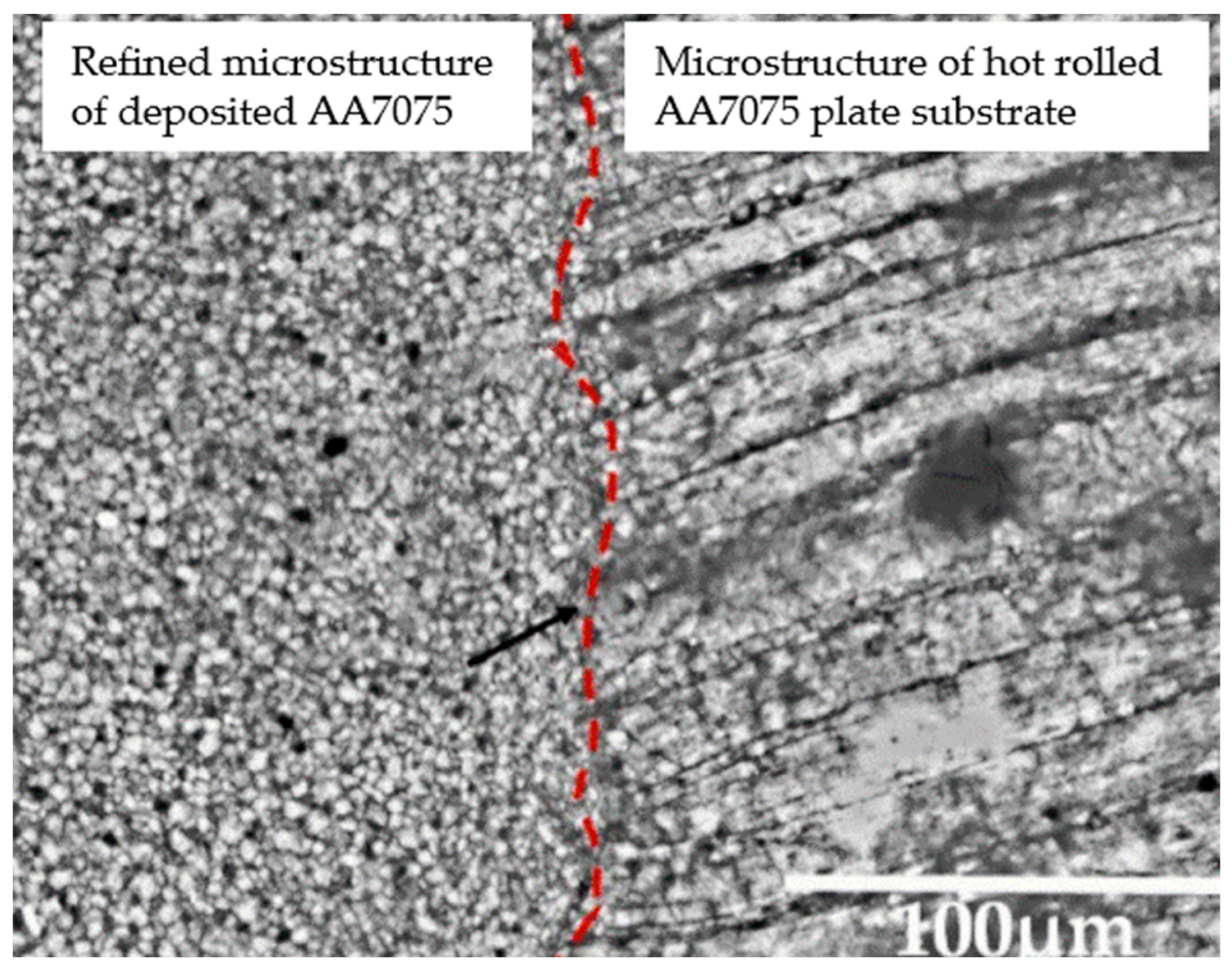
- Wang, M.; Ventzke, V.; Kashaev, N. Wire-based laser directed energy deposition of AA7075: Effect of process parameters on microstructure and mechanical properties. J. Mater. Res. Technol. 2022, 21, 388–403. [Google Scholar] [CrossRef]
- Liu, G.; Su, Y.; Pi, X.; Xin, S.; Li, K.; Liu, D.; Lin, Y. Achieving high strength 316L stainless steel by laser directed energy deposition-ultrasonic rolling hybrid process. Mater. Sci. Eng. A 2024, 903, 146665. [Google Scholar] [CrossRef]
- Wang, J.; Wang, Y.; Su, Y.; Shi, J. Evaluation of in-situ alloyed Inconel 625 from elemental powders by laser directed energy deposition. Mater. Sci. Eng. A 2022, 830, 142296. [Google Scholar] [CrossRef]
- Cen, L.; Zhou, S.; Gao, M. Controlling macroscopic segregation of the directed energy deposited Cu–Fe alloy by laser oscillation. Mater. Sci. Eng. A 2023, 886, 145637. [Google Scholar] [CrossRef]
- Zhang, X.; Li, W.; Liou, F. Additive manufacturing of cobalt-based alloy on tool steel by directed energy deposition. Opt. Laser Technol. 2022, 148, 107738. [Google Scholar] [CrossRef]
- Pixner, F.; Warchomicka, F.; Peter, P.; Steuwer, A.; Colliander, M.H.; Pederson, R.; Enzinger, N. Wire-based additive manufacturing of Ti-6Al-4V using electron beam technique. Materials 2020, 13, 3310. [Google Scholar] [CrossRef]
- Zhang, G.; Liu, W.; Zhang, P.; Xiong, H.; Gao, J.; Yu, H.; Yuan, H. Chemical composition, microstructure, tensile and creep behavior of Ti60 alloy fabricated via electron beam directed energy deposition. Materials 2022, 15, 3109. [Google Scholar] [CrossRef] [PubMed]
- Zhao, C.; Wang, L.; Wang, B.; Yao, L.; Jiang, B.; Luo, L.; Chen, R.; Su, Y.; Guo, J. Microstructure evolution and mechanical properties of wire-fed electron beam directed energy deposition repaired GH4169 superalloy. J. Mater. Res. Technol. 2023, 27, 7259–7270. [Google Scholar] [CrossRef]
- Utyaganova, V.; Filippov, A.V.; Shamarin, N.; Vorontsov, A.; Savchenko, N.; Fortuna, S.; Gurianov, D.; Chumaevskii, A.; Rubtsov, V.; Tarasov, S.Y. Controlling the porosity using exponential decay heat input regimes during electron beam wire-feed additive manufacturing of Al-Mg alloy. Int. J. Adv. Manuf. Technol. 2020, 108, 2823–2838. [Google Scholar] [CrossRef]
- Pu, Z.; Du, D.; Zhang, D.; Xi, R.; Wang, X.; Chang, B. Study on the role of carbon in modifying second phase and improving tensile properties of NiTi shape memory alloys fabricated by electron beam directed energy deposition. Addit. Manuf. 2023, 75, 103733. [Google Scholar] [CrossRef]
- Yu, Z.; Li, C.; Liu, C. Fabricating large scale titanium alloy thin-walled double-sided part by hot-wire arc additive manufacturing. J. Phys. Conf. Ser. 2024, 2671, 012004. [Google Scholar] [CrossRef]
- Yu, B.; Chen, Z.; Wang, P.; Liu, Y.; Song, X.; Dong, P. Fatigue and anisotropic behavior of wire-arc additive manufactured TC17 titanium alloy. J. Mater. Res. Technol. 2024, 28, 3463–3474. [Google Scholar] [CrossRef]
- Dai, H.; Zhao, H.; Xia, Y.; Cai, X.; Dong, B.; Lin, S.; Zhao, Y. Wire arc additive manufacturing of ZL205A: Heat input effect on the forming quality, pore defects and mechanical properties. J. Alloys Compd. 2024, 1005, 175777. [Google Scholar] [CrossRef]
- Fang, X.; Yang, J.; Jiang, X.; Li, X.; Chen, R.; Huang, K. Wire-arc directed energy deposited high-performance AZ31 magnesium alloy via a novel interlayer hammering treatment. Mater. Sci. Eng. A 2024, 889, 145864. [Google Scholar] [CrossRef]
- Xie, J.; Zhou, Y.; Zhou, C.; Li, X.; Chen, Y. Microstructure and mechanical properties of Mg–Li alloys fabricated by wire arc additive manufacturing. J. Mater. Res. Technol. 2024, 29, 3487–3493. [Google Scholar] [CrossRef]
- Karmuhilan, M.; Kumanan, S. Mechanical Anisotropy and Failure Analysis of Inconel 625 Parts Manufactured Using Wire and Arc Additive Manufacturing (WAAM). J. Fail. Anal. Prev. 2024, 24, 583–590. [Google Scholar] [CrossRef]
- Chen, L.; Oliveira, J.P.; Yan, X.; Pang, B.; Ke, W.; Shen, J.; Teshome, F.B.; Schell, N.; Zhou, N.; Peng, B. Microstructure and Phase Transformation Behavior of NiTiCu Shape Memory Alloys Produced Using Twin-Wire Arc Additive Manufacturing. Addit. Manuf. Front. 2024, 3, 200132. [Google Scholar] [CrossRef]
- Lett, S.; Cormier, J.; Quet, A.; Villechaise, P.; Meillot, E.; Hémery, S. Microstructure Optimization of Cold Sprayed Ti-6Al-4V using Post-Process Heat Treatment for Improved Mechanical Properties. Addit. Manuf. 2024, 86, 104168. [Google Scholar] [CrossRef]
- Kondas, J.; Guagliano, M.; Bagherifard, S.; Singh, R.; Cizek, J.; Lukac, F.; Konopik, P.; Rzepa, S. Importance of feedstock powder selection for mechanical properties improvement of cold spray additively manufactured Ti6Al4V deposits. Addit. Manuf. Lett. 2024, 9, 100199. [Google Scholar] [CrossRef]
- Hutasoit, N.; Rashid, R.A.R.; Palanisamy, S.; Duguid, A. Effect of build orientation and post-build heat treatment on the mechanical properties of cold spray additively manufactured copper parts. Int. J. Adv. Manuf. Technol. 2020, 110, 2341–2357. [Google Scholar] [CrossRef]
- Hutasoit, N.; Javed, M.A.; Rashid, R.A.R.; Wade, S.; Palanisamy, S. Effects of build orientation and heat treatment on microstructure, mechanical and corrosion properties of Al6061 aluminium parts built by cold spray additive manufacturing process. Int. J. Mech. Sci. 2021, 204, 106526. [Google Scholar] [CrossRef]
- Huang, C.J.; Chen, T.; Fu, B.L.; Zhang, Z.M.; List, A.; Wiehler, L.; Klusemann, B.; Li, W.Y.; Gärtner, F.; Klassen, T. Ductility and fracture behavior of cold spray additive manufactured zinc. Addit. Manuf. 2024, 89, 104310. [Google Scholar] [CrossRef]
- Vaz, R.F.; Luzin, V.; Salvemini, F.; Ribamar, G.G.; Ávila, J.A.; Albaladejo, V.; Sanchez, J.; Cano, I.G. The effect of the deposition strategy and heat treatment on cold spray additive manufactured 316L stainless steel. Adv. Eng. Mater. 2024, 26, 2302156. [Google Scholar] [CrossRef]
- Elangovan, S.; VK, M.J.; Saravanan, M.; Subash, P. Wire Arc Additive Manufacturing of Aluminium Alloys using GTAW-A Review. In Proceedings of the International Conference on Advancements in Materials, Design and Manufacturing for Sustainable Development, ICAMDMS 2024, Coimbatore, Tamil Nadu, India, 23–24 February 2024. [Google Scholar]
- Panicker, C.T.J.; Senthilkumar, V. Effect of arc rotation on the enhancement of mechanical properties of ER70S6 in WAAM. Vacuum 2024, 220, 112837. [Google Scholar] [CrossRef]
- Sankar, N.; Malarvizhi, S.; Balasubramanian, V. Effect of Rotating Arc on Mechanical Properties and Microstructural Characteristics of Gas Metal Arc Welded Carbon Steel Joints. Metallogr. Microstruct. Anal. 2021, 10, 541–559. [Google Scholar] [CrossRef]
- Sankar, N.; Malarvizhi, S.; Balasubramanian, V. Performance and Characteristics of Stationary Arc and Rotating Arc-Gas Metal Arc Welded DMR 249 Naval Grade Steel Joints. Mater. Perform. Charact. 2022, 11, 170–192. [Google Scholar] [CrossRef]
- Yin, S.; Cavaliere, P.; Aldwell, B.; Jenkins, R.; Liao, H.; Li, W.; Lupoi, R. Cold spray additive manufacturing and repair: Fundamentals and applications. Addit. Manuf. 2018, 21, 628–650. [Google Scholar] [CrossRef]
- Xia, C.; Pan, Z.; Polden, J.; Li, H.; Xu, Y.; Chen, S.; Zhang, Y. A review on wire arc additive manufacturing: Monitoring, control and a framework of automated system. J. Manuf. Syst. 2020, 57, 31–45. [Google Scholar] [CrossRef]
- Qi, H.; Azer, M.; Ritter, A. Studies of standard heat treatment effects on microstructure and mechanical properties of laser net shape manufactured Inconel 718. Metall. Mater. Trans. A 2009, 40, 2410–2422. [Google Scholar] [CrossRef]
- Stevens, E.L.; Toman, J.; To, A.C.; Chmielus, M. Variation of hardness, microstructure, and Laves phase distribution in direct laser deposited alloy 718 cuboids. Mater. Des. 2017, 119, 188–198. [Google Scholar] [CrossRef]
- Neikter, M.; Bhaskar, P.; Singh, S.; Kadoi, K.; Lyphout, C.; Svahn, F.; Pederson, R. Tensile properties of laser powder bed fusion built JBK-75 austenitic stainless steel. Mater. Sci. Eng. A 2023, 874, 144911. [Google Scholar] [CrossRef]
- Chen, X.; Xie, X.; Wu, H.; Ji, X.; Shen, H.; Xue, M.; Wu, H.; Chao, Q.; Fan, G.; Liu, Q. In-situ control of residual stress and its distribution in a titanium alloy additively manufactured by laser powder bed fusion. Mater. Charact. 2023, 201, 112953. [Google Scholar] [CrossRef]
- Chen, Y.; Xiao, C.; Zhu, S.; Li, Z.; Yang, W.; Zhao, F.; Yu, S.; Shi, Y. Microstructure characterization and mechanical properties of crack-free Al-Cu-Mg-Y alloy fabricated by laser powder bed fusion. Addit. Manuf. 2022, 58, 103006. [Google Scholar] [CrossRef]
- Li, M.; Yao, S.; Wang, J.; Chen, Z.; Zhang, G.; Zhang, S.; Li, Y. Role of Er on the densification, microstructure and mechanical properties of 7075 aluminium alloys manufactured by laser powder bed fusion. J. Mater. Res. Technol. 2022, 20, 2021–2033. [Google Scholar] [CrossRef]
- Li, R.; Kong, D.; He, K.; Dong, C. Superior thermal stability and strength of additively manufactured CoCrFeMnNi high-entropy alloy via NbC decorated sub-micro dislocation cells. Scr. Mater. 2023, 230, 115401. [Google Scholar] [CrossRef]
- Li, X.; Fang, X.; Jiang, X.; Duan, Y.; Li, Y.; Zhang, H.; Li, X.; Huang, K. Additively manufactured high-performance AZ91D magnesium alloys with excellent strength and ductility via nanoparticles reinforcement. Addit. Manuf. 2023, 69, 103550. [Google Scholar] [CrossRef]
- Tumkur, T.U.; Voisin, T.; Shi, R.; Depond, P.J.; Roehling, T.T.; Wu, S.; Crumb, M.F.; Roehling, J.D.; Guss, G.; Khairallah, S.A. Nondiffractive beam shaping for enhanced optothermal control in metal additive manufacturing. Sci. Adv. 2021, 7, eabg9358. [Google Scholar] [CrossRef]
- Roehling, T.T.; Shi, R.; Khairallah, S.A.; Roehling, J.D.; Guss, G.M.; McKeown, J.T.; Matthews, M.J. Controlling grain nucleation and morphology by laser beam shaping in metal additive manufacturing. Mater. Des. 2020, 195, 109071. [Google Scholar] [CrossRef]
- Roehling, J.D.; Smith, W.L.; Roehling, T.T.; Vrancken, B.; Guss, G.M.; McKeown, J.T.; Hill, M.R.; Matthews, M.J. Reducing residual stress by selective large-area diode surface heating during laser powder bed fusion additive manufacturing. Addit. Manuf. 2019, 28, 228–235. [Google Scholar] [CrossRef]
- Zhang, X.; He, Y.; Zhao, S.; Ding, H.; Hu, Y. Innovative liquid metal strategy for real-time thermal control in additive manufacturing. J. Mater. Process. Technol. 2023, 322, 118166. [Google Scholar] [CrossRef]
- Liu, S.; Shin, Y.C. Additive manufacturing of Ti6Al4V alloy: A review. Mater. Des. 2019, 164, 107552. [Google Scholar] [CrossRef]
- Zhong, C.; Liu, J.; Zhao, T.; Schopphoven, T.; Fu, J.; Gasser, A.; Schleifenbaum, J.H. Laser metal deposition of Ti6Al4V—A brief review. Appl. Sci. 2020, 10, 764. [Google Scholar] [CrossRef]
- Harun, W.; Manam, N.; Kamariah, M.; Sharif, S.; Zulkifly, A.; Ahmad, I.; Miura, H. A review of powdered additive manufacturing techniques for Ti-6al-4v biomedical applications. Powder Technol. 2018, 331, 74–97. [Google Scholar] [CrossRef]
- Raami, L.; Peura, P. Influence of initial quenching on the microstructure and mechanical properties of quenched and partitioned ferritic stainless steels. Mater. Sci. Eng. A 2022, 847, 143339. [Google Scholar] [CrossRef]
- Liu, W.; Wu, Y.; He, J.; Nieh, T.; Lu, Z. Grain growth and the Hall–Petch relationship in a high-entropy FeCrNiCoMn alloy. Scr. Mater. 2013, 68, 526–529. [Google Scholar] [CrossRef]
- Flemings, M.C. Behavior of metal alloys in the semisolid state. Metall. Trans. A 1991, 22, 957–981. [Google Scholar] [CrossRef]
- Colegrove, P.A.; Martina, F.; Roy, M.J.; Szost, B.A.; Terzi, S.; Williams, S.W.; Withers, P.J.; Jarvis, D. High pressure interpass rolling of wire+ arc additively manufactured titanium components. Adv. Mater. Res. 2014, 996, 694–700. [Google Scholar] [CrossRef]
- Xie, Y.; Zhang, H.; Zhou, F. Improvement in geometrical accuracy and mechanical property for arc-based additive manufacturing using metamorphic rolling mechanism. J. Manuf. Sci. Eng. 2016, 138, 111002. [Google Scholar] [CrossRef]
- Hai-ou, Z.; Wang, R.; Liang, L.; Gui-lan, W. HDMR technology for the aircraft metal part. Rapid Prototyp. J. 2016, 22, 857–863. [Google Scholar] [CrossRef]
- Duarte, V.R.; Rodrigues, T.A.; Schell, N.; Miranda, R.; Oliveira, J.P.; Santos, T.G. Hot forging wire and arc additive manufacturing (HF-WAAM). Addit. Manuf. 2020, 35, 101193. [Google Scholar] [CrossRef]
- D’Andrea, D. Additive manufacturing of AISI 316L stainless steel: A review. Metals 2023, 13, 1370. [Google Scholar] [CrossRef]
- Majumdar, J.D.; Kumar, A.; Pityana, S.; Manna, I. Laser surface melting of AISI 316L stainless steel for bio-implant application. Proc. Natl. Acad. Sci. India Sect. A Phys. Sci. 2018, 88, 387–403. [Google Scholar] [CrossRef]
- Pradeep, P.; Kumar, V.A.; Sriranganath, A.; Singh, S.K.; Sahu, A.; Kumar, T.S.; Narayanan, P.R.; Arumugam, M.; Mohan, M. Characterization and qualification of LPBF additively manufactured AISI-316L stainless steel brackets for aerospace application. Trans. Indian Natl. Acad. Eng. 2020, 5, 603–616. [Google Scholar] [CrossRef]
- Engström, S. A Review of the MIM Process and Its Optimization. Available online: https://api.semanticscholar.org/CorpusID:173174033 (accessed on 19 August 2024).
- Kukla, C.; Gonzalez-Gutierrez, J.; Duretek, I.; Schuschnigg, S.; Holzer, C. Effect of particle size on the properties of highly-filled polymers for fused filament fabrication. AIP Conf. Proc. 2017, 1914, 190006. [Google Scholar]
- Brostow, W.; Buchman, A.; Buchman, E.; Olea-Mejia, O. Microhybrids of metal powder incorporated in polymeric matrices: Friction, mechanical behavior, and microstructure. Polym. Eng. Sci. 2008, 48, 1977–1981. [Google Scholar] [CrossRef]
- Uhm, Y.R.; Kim, J.; Son, K.J.; Kim, C.S. Effect of particle size, dispersion, and particle–matrix adhesion on W reinforced polymer composites. Res. Chem. Intermed. 2014, 40, 2145–2153. [Google Scholar] [CrossRef]
- González-Gutiérrez, J.; Stringari, G.B.; Emri, I. Powder injection molding of metal and ceramic parts. In Some Critical Issues for Injection Molding; IntechOpen: London, UK, 2012; pp. 65–88. [Google Scholar]
- Ren, L.; Zhou, X.; Song, Z.; Zhao, C.; Liu, Q.; Xue, J.; Li, X. Process parameter optimization of extrusion-based 3D metal printing utilizing PW–LDPE–SA binder system. Materials 2017, 10, 305. [Google Scholar] [CrossRef]
- Bragaglia, M.; Mariani, M.; Sergi, C.; Sarasini, F.; Tirillo, J.; Nanni, F. Polylactic acid as biobased binder for the production of 3D printing filaments for Ti6Al4V alloy manufacturing via bound metal deposition. J. Mater. Res. Technol. 2023, 27, 168–181. [Google Scholar] [CrossRef]
- Suwanpreecha, C.; Manonukul, A. A review on material extrusion additive manufacturing of metal and how it compares with metal injection moulding. Metals 2022, 12, 429. [Google Scholar] [CrossRef]
- Riaz, A.; Töllner, P.; Ahrend, A.; Springer, A.; Milkereit, B.; Seitz, H. Optimization of composite extrusion modeling process parameters for 3D printing of low-alloy steel AISI 8740 using metal injection moulding feedstock. Mater. Des. 2022, 219, 110814. [Google Scholar] [CrossRef]
- Zhang, Y.; Roch, A. Fused filament fabrication and sintering of 17-4PH stainless steel. Manuf. Lett. 2022, 33, 29–32. [Google Scholar] [CrossRef]
- Ma, M.; Hu, Z.; Zhang, K.; Wang, Z.; Zhang, H. A metal additive manufacturing methodology: Pneumatic extruding direct-writing deposition. Addit. Manuf. 2021, 46, 102217. [Google Scholar] [CrossRef]
- Hu, G.; Huang, B.; Xie, H.; Zuo, L.; Wang, N.; Li, D.; Liu, Y.; Zhang, Y. Ultrasonic-assisted direct writing metal additive manufacturing technique. J. Mater. Process. Technol. 2023, 312, 117830. [Google Scholar] [CrossRef]
- Chen, W.; Thornley, L.; Coe, H.G.; Tonneslan, S.J.; Vericella, J.J.; Zhu, C.; Duoss, E.B.; Hunt, R.M.; Wight, M.J.; Apelian, D. Direct metal writing: Controlling the rheology through microstructure. Appl. Phys. Lett. 2017, 110, 094104. [Google Scholar] [CrossRef]
- Fei, Y.; Xu, J.; Yao, D.; Chiou, R.; Zhou, J. Design, simulation, and experiments for direct thixotropic metal 3D printing. Mater. Sci. Addit. Manuf. 2022. [Google Scholar] [CrossRef]
- Altıparmak, S.C.; Yardley, V.A.; Shi, Z.; Lin, J. Extrusion-based additive manufacturing technologies: State of the art and future perspectives. J. Manuf. Process. 2022, 83, 607–636. [Google Scholar] [CrossRef]
- Tateno, T.; Kakuta, A.; Ogo, H.; Kimoto, T. Ultrasonic vibration-assisted extrusion of metal powder suspension for additive manufacturing. Int. J. Autom. Technol. 2018, 12, 775–783. [Google Scholar] [CrossRef]
- Matsusaka, S.; Yamamoto, K.; Masuda, H. Micro-feeding of a fine powder using a vibrating capillary tube. Adv. Powder Technol. 1996, 7, 141–151. [Google Scholar] [CrossRef]
- Thompson, Y.; Zissel, K.; Förner, A.; Gonzalez-Gutierrez, J.; Kukla, C.; Neumeier, S.; Felfer, P. Metal fused filament fabrication of the nickel-base superalloy IN 718. J. Mater. Sci. 2022, 57, 9541–9555. [Google Scholar] [CrossRef]
- Yi, S.; Yi, Z.-H.; Ting, S.; Xiong, H.-W.; Xiao, K.; Zhang, L.; Zhou, K.-C. Microstructure and mechanical properties of 7075 aluminum alloy prepared by metal fused deposition modeling. Trans. Nonferr. Met. Soc. China 2024, 34, 2108–2119. [Google Scholar]
- Atatreh, S.; Alyammahi, M.S.; Vasilyan, H.; Alkindi, T.; Susantyoko, R.A. Evaluation of the infill design on the tensile properties of metal parts produced by fused filament fabrication. Results Eng. 2023, 17, 100954. [Google Scholar] [CrossRef]
- Liu, B.; Wang, Y.; Lin, Z.; Zhang, T. Creating metal parts by fused deposition modeling and sintering. Mater. Lett. 2020, 263, 127252. [Google Scholar] [CrossRef]
- Wagner, M.A.; Ocana-Pujol, J.L.; Hadian, A.; Clemens, F.; Spolenak, R. Filament extrusion-based additive manufacturing of NiTi shape memory alloys. Mater. Des. 2023, 225, 111418. [Google Scholar] [CrossRef]
- Yu, Y.; Liu, F.; Liu, J. Direct 3D printing of low melting point alloy via adhesion mechanism. Rapid Prototyp. J. 2017, 23, 642–650. [Google Scholar] [CrossRef]
- Fang, X.; Du, J.; Wei, Z.; Wang, X.; He, P.; Bai, H.; Wang, B.; Chen, J.; Geng, R.; Lu, B. Study on metal deposit in the fused-coating based additive manufacturing. Procedia Cirp 2016, 55, 115–121. [Google Scholar] [CrossRef]
- Oleff, A.; Küster, B.; Stonis, M.; Overmeyer, L. Process monitoring for material extrusion additive manufacturing: A state-of-the-art review. Prog. Addit. Manuf. 2021, 6, 705–730. [Google Scholar] [CrossRef]
- Singh, P.; Balla, V.K.; Atre, S.V.; German, R.M.; Kate, K.H. Factors affecting properties of Ti-6Al-4V alloy additive manufactured by metal fused filament fabrication. Powder Technol. 2021, 386, 9–19. [Google Scholar] [CrossRef]
- Wang, Y.; Zhang, L.; Li, X.; Yan, Z. On hot isostatic pressing sintering of fused filament fabricated 316L stainless steel—Evaluation of microstructure, porosity, and tensile properties. Mater. Lett. 2021, 296, 129854. [Google Scholar] [CrossRef]
- Malagutti, L.; Ronconi, G.; Zanelli, M.; Mollica, F.; Mazzanti, V. A post-processing method for improving the mechanical properties of fused-filament-fabricated 3D-printed parts. Processes 2022, 10, 2399. [Google Scholar] [CrossRef]
- Waalkes, L.; Längerich, J.; Holbe, F.; Emmelmann, C. Feasibility study on piston-based feedstock fabrication with Ti-6Al-4V metal injection molding feedstock. Addit. Manuf. 2020, 35, 101207. [Google Scholar] [CrossRef]
- Tosto, C.; Tirillò, J.; Sarasini, F.; Cicala, G. Hybrid metal/polymer filaments for fused filament fabrication (FFF) to print metal parts. Appl. Sci. 2021, 11, 1444. [Google Scholar] [CrossRef]
- Jiang, D.; Ning, F. Fused filament fabrication of biodegradable PLA/316L composite scaffolds: Effects of metal particle content. Procedia Manuf. 2020, 48, 755–762. [Google Scholar] [CrossRef]
- Buj-Corral, I.; Sanz-Fraile, H.; Ulldemolins, A.; Tejo-Otero, A.; Domínguez-Fernández, A.; Almendros, I.; Otero, J. Characterization of 3D printed metal-PLA composite scaffolds for biomedical applications. Polymers 2022, 14, 2754. [Google Scholar] [CrossRef]
- Ali, F.; Kalva, S.N.; Koç, M. Additive manufacturing of polymer/Mg-based composites for porous tissue scaffolds. Polymers 2022, 14, 5460. [Google Scholar] [CrossRef]
- Nguyen, H.D.; Pramanik, A.; Basak, A.; Dong, Y.; Prakash, C.; Debnath, S.; Shankar, S.; Jawahir, I.; Dixit, S.; Buddhi, D. A critical review on additive manufacturing of Ti-6Al-4V alloy: Microstructure and mechanical properties. J. Mater. Res. Technol. 2022, 18, 4641–4661. [Google Scholar] [CrossRef]
- Chastand, V.; Quaegebeur, P.; Maia, W.; Charkaluk, E. Comparative study of fatigue properties of Ti-6Al-4V specimens built by electron beam melting (EBM) and selective laser melting (SLM). Mater. Charact. 2018, 143, 76–81. [Google Scholar] [CrossRef]
- Sterling, A.J.; Torries, B.; Shamsaei, N.; Thompson, S.M.; Seely, D.W. Fatigue behavior and failure mechanisms of direct laser deposited Ti–6Al–4V. Mater. Sci. Eng. A 2016, 655, 100–112. [Google Scholar] [CrossRef]
- Thompson, Y.; Polzer, M.; Gonzalez-Gutierrez, J.; Kasian, O.; Heckl, J.P.; Dalbauer, V.; Kukla, C.; Felfer, P.J. Fused Filament Fabrication-Based Additive Manufacturing of Commercially Pure Titanium. Adv. Eng. Mater. 2021, 23, 2100380. [Google Scholar] [CrossRef]
- Zhang, Q.; Li, H.; Han, B.; Huang, K.; Fang, X.; Chen, Z. A distinctive Pb-Sn semi-solid additive manufacturing using wire feeding and extrusion. J. Manuf. Process. 2022, 80, 247–258. [Google Scholar] [CrossRef]
- Nezic, N.; Speth, M.; Rouven Riedmüller, K.; Liewald, M. Development of a new method utilizing semi-solid aluminum wires for extrusion based additive manufacturing. Mater. Form. ESAFORM 2023 2023, 28, 75. [Google Scholar]
- Lima, D.D.; Campo, K.N.; Button, S.T.; Caram, R. 3D thixo-printing: A novel approach for additive manufacturing of biodegradable Mg-Zn alloys. Mater. Des. 2020, 196, 109161. [Google Scholar] [CrossRef]
- de Lima, D.D.; Campo, K.N.; Caram, R. Coupling thermodynamic simulation and thermal analysis to select Sn–Bi alloys for semisolid additive manufacturing. J. Therm. Anal. Calorim. 2023, 148, 9423–9433. [Google Scholar] [CrossRef]
- Hu, Y.; Guo, X.; Qiao, Y.; Wang, X.; Lin, Q. Preparation of medical Mg–Zn alloys and the effect of different zinc contents on the alloy. J. Mater. Sci. Mater. Med. 2022, 33, 9. [Google Scholar] [CrossRef]
- Chen, D.; He, Y.; Tao, H.; Zhang, Y.; Jiang, Y.; Zhang, X.; Zhang, S. Biocompatibility of magnesium-zinc alloy in biodegradable orthopedic implants. Int. J. Mol. Med. 2011, 28, 343–348. [Google Scholar]
- Frongia, F.; Pilloni, M.; Scano, A.; Ardu, A.; Cannas, C.; Musinu, A.; Borzone, G.; Delsante, S.; Novakovic, R.; Ennas, G. Synthesis and melting behaviour of Bi, Sn and Sn–Bi nanostructured alloy. J. Alloys Compd. 2015, 623, 7–14. [Google Scholar] [CrossRef]
- Rong, W.; Shan, Z.; Wang, B.; Wang, Y.; Wang, J. Microstructure evolution of 2A12 aluminum alloy under isothermal heat treatment direct writing process. Materials 2022, 15, 6279. [Google Scholar] [CrossRef] [PubMed]
- Saklakoglu, N.; Saklakoglu, I.E.; Tanoglu, M.; Oztas, O.; Cubukcuoglu, O. Mechanical properties and microstructural evaluation of AA5013 aluminum alloy treated in the semi-solid state by SIMA process. J. Mater. Process. Technol. 2004, 148, 103–107. [Google Scholar] [CrossRef]
- Janudom, S.; Wannasin, J.; Basem, J.; Wisutmethangoon, S. Characterization of flow behavior of semi-solid slurries containing low solid fractions in high-pressure die casting. Acta Mater. 2013, 61, 6267–6275. [Google Scholar] [CrossRef]
- Englert, L.; Klumpp, A.; Ausländer, A.; Schulze, V.; Dietrich, S. Semi-solid wire-feed additive manufacturing of AlSi7Mg by direct induction heating. Addit. Manuf. Lett. 2022, 3, 100067. [Google Scholar] [CrossRef]
- Sharma, G.K.; Pant, P.; Jain, P.K.; Kankar, P.K.; Tandon, P. Analysis of novel induction heating extruder for additive manufacturing using aluminum filament. Proc. Inst. Mech. Eng. Part B J. Eng. Manuf. 2021, 235, 1961–1970. [Google Scholar] [CrossRef]
- Harshavardhana, N.; Sivam, S.P.S.S.; Savio, R.R.; Honymon, A.; Apramayan, V.; Kumar, G.; Saxena, A.K. Effect of Heat Treatment on Wire+ Arc Additive Manufactured Aluminum 5356 Alloy: Mechanical Properties and Microstructure Correlation. Phys. Met. Metallogr. 2023, 124, 1845–1855. [Google Scholar] [CrossRef]
- Rooy, E.L. Introduction to aluminum and aluminum alloys. In Properties and Selection: Nonferrous Alloys and Special-Purpose Materials; ASM International: Materials Park, OH, USA, 1990. [Google Scholar]
- Li, D. A review of microstructure evolution during ultrasonic additive manufacturing. Int. J. Adv. Manuf. Technol. 2021, 113, 1–19. [Google Scholar] [CrossRef]
- Massey, C.P.; Havrilak, C.J.; Gussev, M.N.; Terrani, K.A.; Nelson, A.T. Ultrasonic additive manufacturing of zirconium: Pilot results. Mater. Lett. 2021, 302, 130330. [Google Scholar] [CrossRef]
- Hehr, A.; Dapino, M.J. Dynamics of ultrasonic additive manufacturing. Ultrasonics 2017, 73, 49–66. [Google Scholar] [CrossRef]
- Levy, A.; Miriyev, A.; Sridharan, N.; Han, T.; Tuval, E.; Babu, S.S.; Dapino, M.J.; Frage, N. Ultrasonic additive manufacturing of steel: Method, post-processing treatments and properties. J. Mater. Process. Technol. 2018, 256, 183–189. [Google Scholar] [CrossRef]
- Gussev, M.N.; Sridharan, N.; Thompson, Z.; Terrani, K.A.; Babu, S. Influence of hot isostatic pressing on the performance of aluminum alloy fabricated by ultrasonic additive manufacturing. Scr. Mater. 2018, 145, 33–36. [Google Scholar] [CrossRef]
- Mishra, R.S.; Haridas, R.S.; Agrawal, P. Friction stir-based additive manufacturing. Sci. Technol. Weld. Join. 2022, 27, 141–165. [Google Scholar] [CrossRef]
- Agrawal, P.; Haridas, R.S.; Yadav, S.; Thapliyal, S.; Gaddam, S.; Verma, R.; Mishra, R.S. Processing-structure-property correlation in additive friction stir deposited Ti-6Al-4V alloy from recycled metal chips. Addit. Manuf. 2021, 47, 102259. [Google Scholar] [CrossRef]
- Haridas, R.S.; Gumaste, A.; Varshney, P.; Manu, B.R.; Kandasamy, K.; Kumar, N.; Mishra, R.S. SolidStir additive manufacturing: A novel deformation-based additive manufacturing using friction stir technology. JOM 2023, 75, 4231–4241. [Google Scholar] [CrossRef]
- Dong, H.; Li, X.; Xu, K.; Zang, Z.; Liu, X.; Zhang, Z.; Xiao, W.; Li, Y. A review on solid-state-based additive friction stir deposition. Aerospace 2022, 9, 565. [Google Scholar] [CrossRef]
- Hassan, A.; Pedapati, S.R.; Awang, M.; Soomro, I.A. A comprehensive review of friction stir additive manufacturing (FSAM) of non-ferrous alloys. Materials 2023, 16, 2723. [Google Scholar] [CrossRef]
- Khodabakhshi, F.; Gerlich, A. Potentials and strategies of solid-state additive friction-stir manufacturing technology: A critical review. J. Manuf. Process. 2018, 36, 77–92. [Google Scholar] [CrossRef]
- Hehr, A.; Wenning, J.; Terrani, K.; Babu, S.S.; Norfolk, M. Five-Axis Ultrasonic Additive Manufacturing for Nuclear Component Manufacture. JOM 2017, 69, 485–490. [Google Scholar] [CrossRef]
- Sridharan, N.; Gussev, M.; Seibert, R.; Parish, C.; Norfolk, M.; Terrani, K.; Babu, S.S. Rationalization of anisotropic mechanical properties of Al-6061 fabricated using ultrasonic additive manufacturing. Acta Mater. 2016, 117, 228–237. [Google Scholar] [CrossRef]
- Zhou, Y.; Wang, Z.; Zhao, J.; Jiang, F. Effect of ultrasonic amplitude on interfacial characteristics and mechanical properties of Ti/Al laminated metal composites fabricated by ultrasonic additive manufacturing. Addit. Manuf. 2023, 74, 103725. [Google Scholar] [CrossRef]
- Zhou, Y.; Jiang, F.; Wang, Z.; Chen, J. Microstructure characteristics and mechanical properties of Cu/Al laminated metal composites fabricated by electropulsing assisted ultrasonic additive manufacturing. J. Mater. Process. Technol. 2023, 313, 117884. [Google Scholar] [CrossRef]
- Wang, B.; Ge, F.; Zhang, H.; Du, R.; Fan, Y.; Pan, J. Interface microstructure and mechanical properties of copper-steel joints with nickel transition layer prepared by ultrasonic additive manufacturing. J. Mater. Res. Technol. 2023, 23, 6150–6161. [Google Scholar] [CrossRef]
- Yoder, J.K.; Griffiths, R.J.; Yu, H.Z. Deformation-based additive manufacturing of 7075 aluminum with wrought-like mechanical properties. Mater. Des. 2021, 198, 109288. [Google Scholar] [CrossRef]
- Xiao, Y.; Li, Y.; Shi, L.; Wu, C.; Liu, H.; Sun, Z. Experimental and numerical analysis of friction stir additive manufacturing of 2024 aluminium alloy. Mater. Today Commun. 2023, 35, 105639. [Google Scholar] [CrossRef]
- He, C.; Li, Y.; Zhang, Z.; Wei, J.; Zhao, X. Investigation on microstructural evolution and property variation along building direction in friction stir additive manufactured Al–Zn–Mg alloy. Mater. Sci. Eng. A 2020, 777, 139035. [Google Scholar] [CrossRef]
- Martin, L.P.; Luccitti, A.; Walluk, M. Evaluation of additive friction stir deposition of AISI 316L for repairing surface material loss in AISI 4340. Int. J. Adv. Manuf. Technol. 2022, 121, 2365–2381. [Google Scholar] [CrossRef]
- Nadimpalli, V.K.; Karthik, G.; Janakiram, G.; Nagy, P.B. Monitoring and repair of defects in ultrasonic additive manufacturing. Int. J. Adv. Manuf. Technol. 2020, 108, 1793–1810. [Google Scholar] [CrossRef]
- Qiao, Q.; Zhou, M.; Gong, X.; Jiang, S.; Lin, Y.; Wang, H.; Lam, W.I.; Qian, H.; Guo, D.; Zhang, D.; et al. In-situ monitoring of additive friction stir deposition of AA6061: Effect of layer thickness on the microstructure and mechanical properties. Addit. Manuf. 2024, 84, 104141. [Google Scholar] [CrossRef]
- Griffiths, R.J.; Petersen, D.T.; Garcia, D.; Yu, H.Z. Additive friction stir-enabled solid-state additive manufacturing for the repair of 7075 aluminum alloy. Appl. Sci. 2019, 9, 3486. [Google Scholar] [CrossRef]
- Javidani, M.; Larouche, D. Application of cast Al–Si alloys in internal combustion engine components. Int. Mater. Rev. 2014, 59, 132–158. [Google Scholar] [CrossRef]
- Alpay, N.; Benehkohal, N.P.; Côté, M.-P.; Demopoulos, G.P.; Brochu, M. Anodized aluminum–silicon alloy counter electrode substrates for next generation solar cell applications. Appl. Surf. Sci. 2015, 356, 317–324. [Google Scholar] [CrossRef]


| DED | ME | SL | |||
|---|---|---|---|---|---|
| Unlimited build size | [32] | Flexible build size | [33] | Large build size | [31] |
| High build rate with challenging process control, high residual stress, poor surface roughness, and low print resolution | [30,33,34,35,36,37,38] | Lower build rate with limited print resolution (depending on nozzle radius), support material needed, anisotropy of properties, and reduced residual stress | [33,34,39] | High volumetric build rate with high mechanical properties; ability to avoid solidification defects | [40,41] |
| Various material choices and multi-material print | [42,43,44] | Various material choices and multi-material print | [45,46,47,48] | Limited material choices and multi-material print | [32,33,49] |
| Energy consumption can be high, depending on process parameters | [50] | Less energy consumption | [51] | Less energy consumption; high machining cost with material waste | [32,52] |
| Suitable for repairing high-value components; need for high-value laser or electron beam; safety concerns of metal powder | [53,54,55] | Suitable for rapid prototyping; affordable cost; simpler and safer mechanism | [45,56,57,58] | Suitable for large geometry, affordable cost, and safe mechanism | [31,59] |
| Post-processing required | [33] | Additional debinding and sintering process; shrinkage due to post-processing | [27] | Additional machining processes | [41,59] |
| Cost (USD) | DED | ME | |
|---|---|---|---|
| LDED | WAAM | MFFF | |
| Machine | 204 | 23.5 | 89.9 |
| Material | 66.7 | 4 | 31 |
| Consumable | 12.8 | 0.44 | 24.6 |
| Post-processing | - | 9.33 | - |
| Labor | 45.5 | 29.3 | 100 |
| Energy | 4.6 | - | - |
| Equipment | 4.9 | - | - |
| Debinding | - | - | 11.6 |
| Sintering | - | - | 70.4 |
| ) | 39,366 | 33,781 | 380,952 |
| Total production cost | 339 | 66.6 | 327.5 |
| 8.6 × 10⁻³ | 1.97 × 10⁻³ | 8.6 × 10⁻⁴ | |
| Material/Alloy | DED Technologies | Mechanical Properties | Defects | Ref. | ||
|---|---|---|---|---|---|---|
| Elongation (%) | YS (MPa) | UTS (MPa) | ||||
| Ti6Al4V | LDED | 8 | 932 | 990 | No defects observed | [83] |
| Ti65 | 9.1 | ~920 | 1058 | - | [84] | |
| Al-Cu | 0.12 | 5.5 | Minor porosity and cracks | [63] | ||
| Al-Si | 1.5 | 2.4 | Lack of fusion | [85] | ||
| Al7075 | 1.1 | 3.9 | 1.9 | Cracks and porosity | [86] | |
| 316L stainless steel | 45.5 | 396 | 682 | Porosity | [87] | |
| IN625 | 23.14 | 675.83 | 1020.93 | Lack of fusion | [88] | |
| Cu-Fe | 4.15 | 328 | 393 | No defects observed | [89] | |
| W50(Cobalt) | 0.2 | - | 30.8 | Porosity and cracks | [90] | |
| Ti-6Al-4V | EB-DED | 4.5 | 846 | 953 | Lack of fusion, bonding defect | [91] |
| Ti60 | 7.1 | 863 | 932 | - | [92] | |
| In718 | 4 | 66 | 75 | Cracks | [93] | |
| Al-Mg | 3.5 | 7 | 5 | Porosity, shrinkage | [94] | |
| Low-carbon Ni-Ti | 6.1 | 450 | 534 | No defects observed | [95] | |
| High-carbon Ni-Ti | 12.8 | 316 | 494 | No defects observed | [95] | |
| Ti-6Al-4V | WAAM | 8.5 | 839 | 917 | Collapse and cracks | [96] |
| TC17 | 5.9 | 1007 | 1049 | Porosity and cracks | [97] | |
| Al-Cu | 8.12 | 101.2 | 232.99 | Porosity | [98] | |
| AZ31 | 26.2 | 102.6 | 239.8 | Porosity | [99] | |
| Mg–Li | 12.4 | - | 201.4 | Microporosity | [100] | |
| IN625 | ~55 | ~430 | ~750 | - | [101] | |
| NiTi | 0.7 | - | 11 | No defects observed | [102] | |
| Ti-6Al-4V | CSAM | ~7 | ~1050 | 1110 | Porosity | [103,104] |
| Copper | 1.5 | - | 9 | Voids, fracture, and porosity | [105] | |
| Al6061 | 5.1–6.1 | - | 238–241 | Porosity | [106] | |
| Zn | 18.4 | - | 92.2 | No defects observed | [107] | |
| 316L stainless steel | - | - | ~420 | Porosity | [108] | |
| Material | ME Technologies | Mechanical Properties | Defects | Ref. | ||
|---|---|---|---|---|---|---|
| Elongation (%) | YS (MPa) | UTS (MPa) | ||||
| Ti-6Al-4V | MFFF | 3 | 10 | 15 | Small porosity | [39] |
| IN718 | 0.5 | - | 140 | Porosity | [157] | |
| Al7075 | 1–2.5 | - | 120–140 | Porosity | [158] | |
| 17-4PH SS | 3.3 | 781 | 1018 | Voids | [159] | |
| 316L SS | 3.8 | 19 | 27 | Porosity | [160] | |
| Copper | 50.49 | 31 | 182 | Voids | [159] | |
| Ni-Ti | 9.2 | 476 | 583 | Porosity | [161] | |
| Bi75-Sn25 | DMW | - | - | - | No obvious defects | [152] |
| Sn63-Pb37 | ~25 | - | 92.2 | Porosity | [151] | |
| In61-B26-Sn9-Ga4 | - | - | - | - | [162] | |
| Sn63Pb37 | - | - | - | Porosity | [163] | |
| Material | SL Technology | Mechanical Property | Defects | Ref | ||
|---|---|---|---|---|---|---|
| Elongation (%) | YS (MPa) | UTS (MPa) | ||||
| Zr | UAM | 3.5 | 28 | 24 | Interfacial porosity | [192] |
| Al6061 | - | - | - | - | [202] | |
| 6 | 221 | 224 | Microvoids | [203] | ||
| Ti/Al laminated | 0.4 | 3 | 1 | Defect-free | [204] | |
| Cu/Al laminated | 4.3 | 261 | 285 | Interfacial segregation | [205] | |
| Cu/SS laminated | 1.61% | - | 165 | Microcracks | [206] | |
| Al7075 | FSAM | 8.2 | 477 | 541 | - | [207] |
| Al6061-T6 | 1.6 | 1 | 3 | Defect-free | [198] | |
| Al2024 | 19 | - | 475 | Microvoids | [208] | |
| Ti-6Al-4V | 1 | 25 | 20 | Interfacial segregation | [197] | |
| Al-Zn-Mg | 8.4–22.3 | - | 352.7 | Kissing bond defects | [209] | |
| AISI4340 steel/AISI316L | 11.2 | 1224 | 1912 | - | [210] | |
Disclaimer/Publisher’s Note: The statements, opinions and data contained in all publications are solely those of the individual author(s) and contributor(s) and not of MDPI and/or the editor(s). MDPI and/or the editor(s) disclaim responsibility for any injury to people or property resulting from any ideas, methods, instructions or products referred to in the content. |
© 2024 by the authors. Licensee MDPI, Basel, Switzerland. This article is an open access article distributed under the terms and conditions of the Creative Commons Attribution (CC BY) license (https://creativecommons.org/licenses/by/4.0/).
Share and Cite
Xu, J.; Fei, Y.; Zhu, Y.; Yu, W.; Yao, D.; Zhou, J.G. A Review of Non-Powder-Bed Metal Additive Manufacturing: Techniques and Challenges. Materials 2024, 17, 4717. https://doi.org/10.3390/ma17194717
Xu J, Fei Y, Zhu Y, Yu W, Yao D, Zhou JG. A Review of Non-Powder-Bed Metal Additive Manufacturing: Techniques and Challenges. Materials. 2024; 17(19):4717. https://doi.org/10.3390/ma17194717
Chicago/Turabian StyleXu, Jie, Yifan Fei, Yuanzhe Zhu, Wei Yu, Donggang Yao, and Jack G. Zhou. 2024. "A Review of Non-Powder-Bed Metal Additive Manufacturing: Techniques and Challenges" Materials 17, no. 19: 4717. https://doi.org/10.3390/ma17194717