3.1. Experimental Results
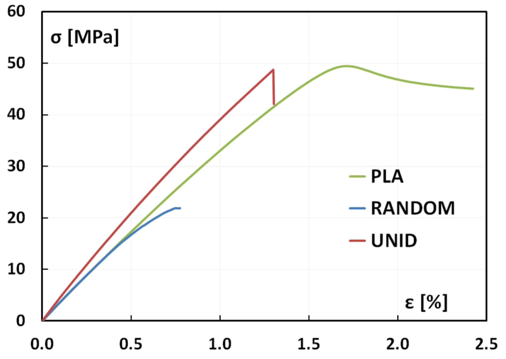
Representative stress-strain curves for each material, shown in
Figure 2, clearly evidence different behaviors between neat PLA and artichoke-based composites, although all of the materials present a very low elongation at break. In particular, PLA exhibits necking before fracture; however, such a phenomenon is only partially observed for the RANDOM composites, and it cannot be evidenced for the UNID composites.
Necking is a mode of ductile flow of a material under tension; thus, the stress-strain curves reported in
Figure 2 suggest that the addition of artichoke fibers reduces the plastic deformation capability of the matrix, thus leading to a more brittle fracture mode.
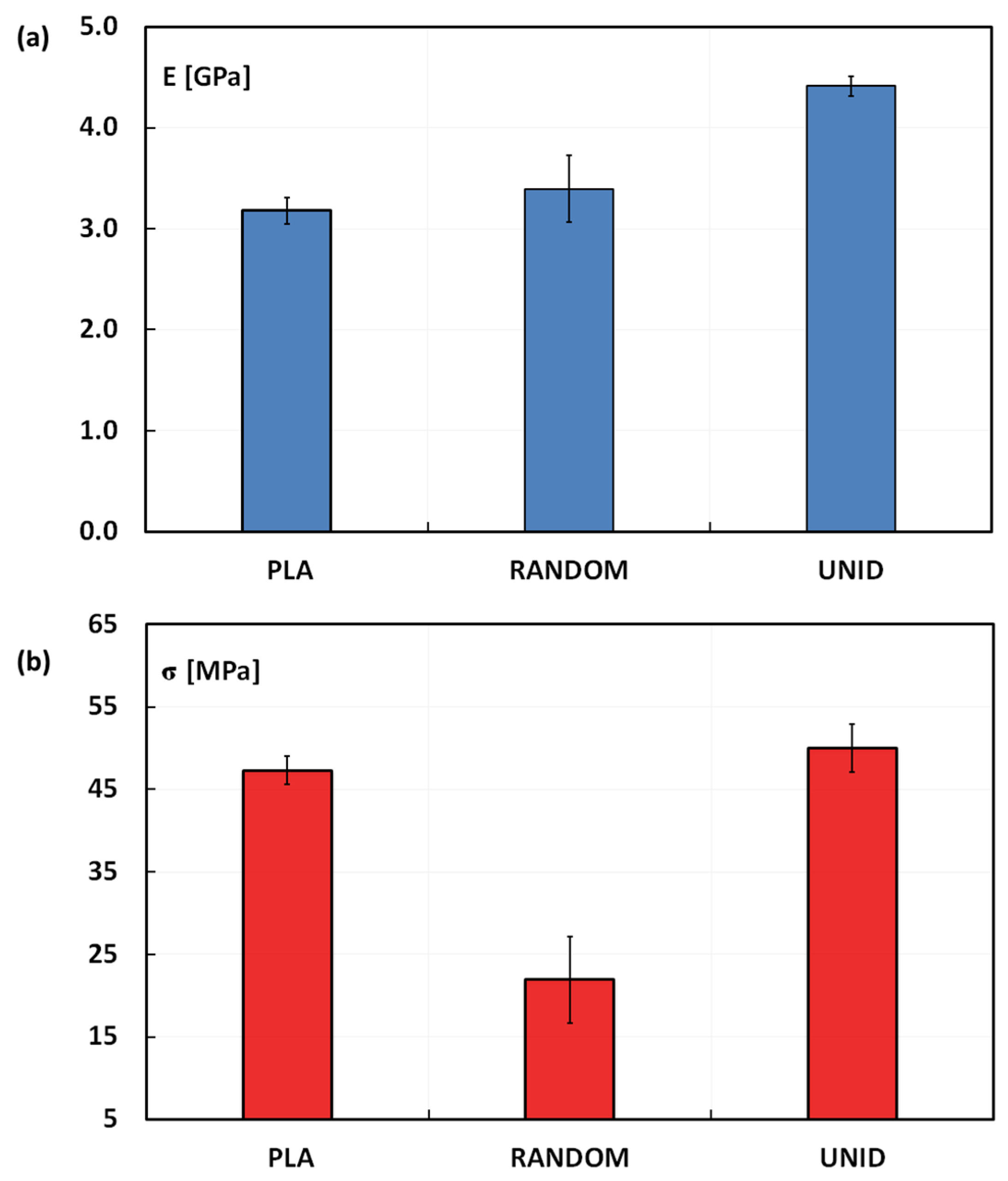
The tensile properties of neat PLA and artichoke composites are reported in
Figure 3. As shown in
Figure 3a, the tensile modulus of UNID composites is significantly higher than that of the neat PLA (
i.e., ~40%), even if the fiber content is just 10% by weight. On the other hand, the composite stiffness is not significantly influenced when the artichoke fibers are randomly disposed within the PLA matrix. As expected, the placement of the fibers along the load direction leads to a better reinforcement effect, since this is the best condition to promote the fiber load carrying. On the other hand, no stiffness improvement was found for RANDOM composites, because just a small portion of the fibers is eventually oriented along the load direction. Moreover, even if oriented along the load direction, the specimen manufacturing (
i.e., dumbbell shape trimming) does not guarantee the fiber continuity, unlike the UNID composites.
Figure 2.
Stress-strain curves obtained from quasi-static tensile tests. UNID, unidirectionally; RANDOM, randomly.
Figure 2.
Stress-strain curves obtained from quasi-static tensile tests. UNID, unidirectionally; RANDOM, randomly.
Figure 3.
(a) Tensile modulus and (b) tensile strength of neat PLA and artichoke composites.
Figure 3.
(a) Tensile modulus and (b) tensile strength of neat PLA and artichoke composites.
As reported in
Figure 3b, the results put into evidence that the UNID composites show an average tensile strength slightly higher than that of neat PLA (50.0 ± 2.9 MPa
vs. 47.3 ± 1.7 MPa). On the contrary, the RANDOM composites experience a tensile strength drop in comparison to neat PLA (
i.e., −53.6%).
In such cases where the fibers mainly bear load (
i.e., UNID composites), the prominent damage modes are fiber fracture, some interface debonding, matrix failure and fiber pull-out [
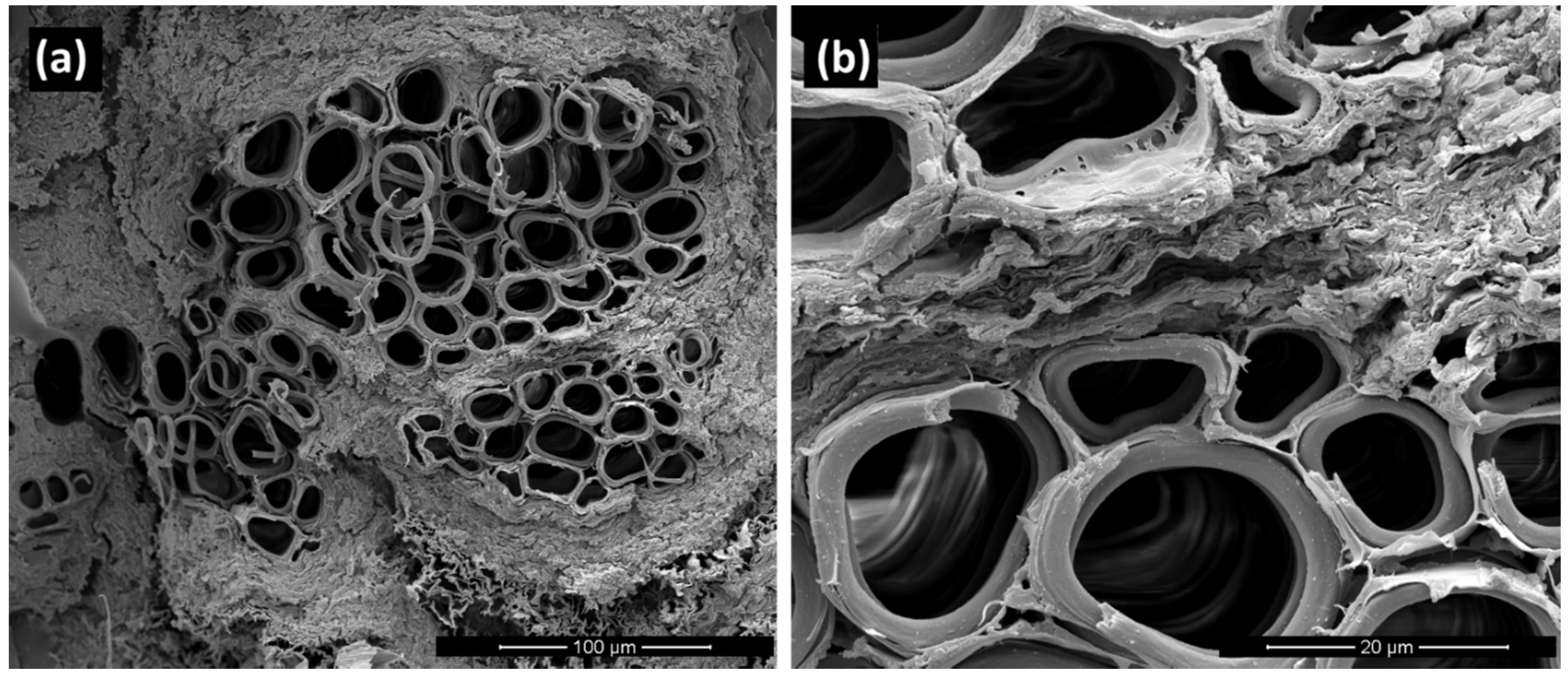
17]. In particular, interface debonding and fiber pull-out are typical failure mechanisms mainly due to the weak fiber-matrix adhesion. The morphology of tensile fractured surfaces reflects the different behaviors of composites prepared by disposing the artichoke fibers randomly or unidirectionally oriented within the PLA matrix.
Indeed, as evidenced by the micrograph of the fracture surface of UNID composites (
Figure 4a), no pull-out damages are visible:
i.e., the specimens fail at one cross-section perpendicular to the loading direction, with all of the fibers failing in the same plane.
This can be attributed to the good fiber-matrix adhesion, as clearly shown in the micrograph at higher magnification, reported in
Figure 4b. This good adhesion does not allow the fibers to rupture at their weakest location above or below the fracture surface, thus not leading to a lower tensile strength of the composites.
Figure 4.
SEM micrographs of the fracture surface of UNID composites at two different magnifications: (a) scale bar 100 µm; (b) scale bar 20 µm.
Figure 4.
SEM micrographs of the fracture surface of UNID composites at two different magnifications: (a) scale bar 100 µm; (b) scale bar 20 µm.
As discussed above, although the fiber-matrix adhesion is obviously not dependent on the orientation of the fibers within the matrix, a decrement was found in the tensile strength of RANDOM composites in comparison with that of neat PLA. This behavior can be attributed to the failure mechanism occurring during the tensile tests of RANDOM composites. In particular, it was observed that the failure of RANDOM composite samples always takes place in correspondence to fibers transversely oriented to the loading direction (see
Figure 5), which represents the weakest point of the whole specimen. Furthermore, it is evident that the fiber is separated into two portions, each remaining joined to the PLA matrix of the two parts of the fractured sample.
Figure 5.
Photograph of a representative fractured RANDOM composite.
Figure 5.
Photograph of a representative fractured RANDOM composite.
This phenomenon can be explained taking into account the typical structure of the artichoke fibers used in this work. Indeed, as is widely known, natural fibers are packed together, forming what are generally called “technical fibers” or “bundles”, composed of several “elementary fibers” glued together mainly by pectin.
The failure mechanism discussed above indicates that the interface strength between the elementary fibers within bundles is weaker than the fiber/PLA matrix adhesion, as already found for similar systems. In particular, Charlet and Béakou [
18] showed that the fiber/fiber interfacial strength within a flax bundle was two- to seven-times lower than those found in the literature for the strength of the interface between flax fibers and classical polymer matrices.
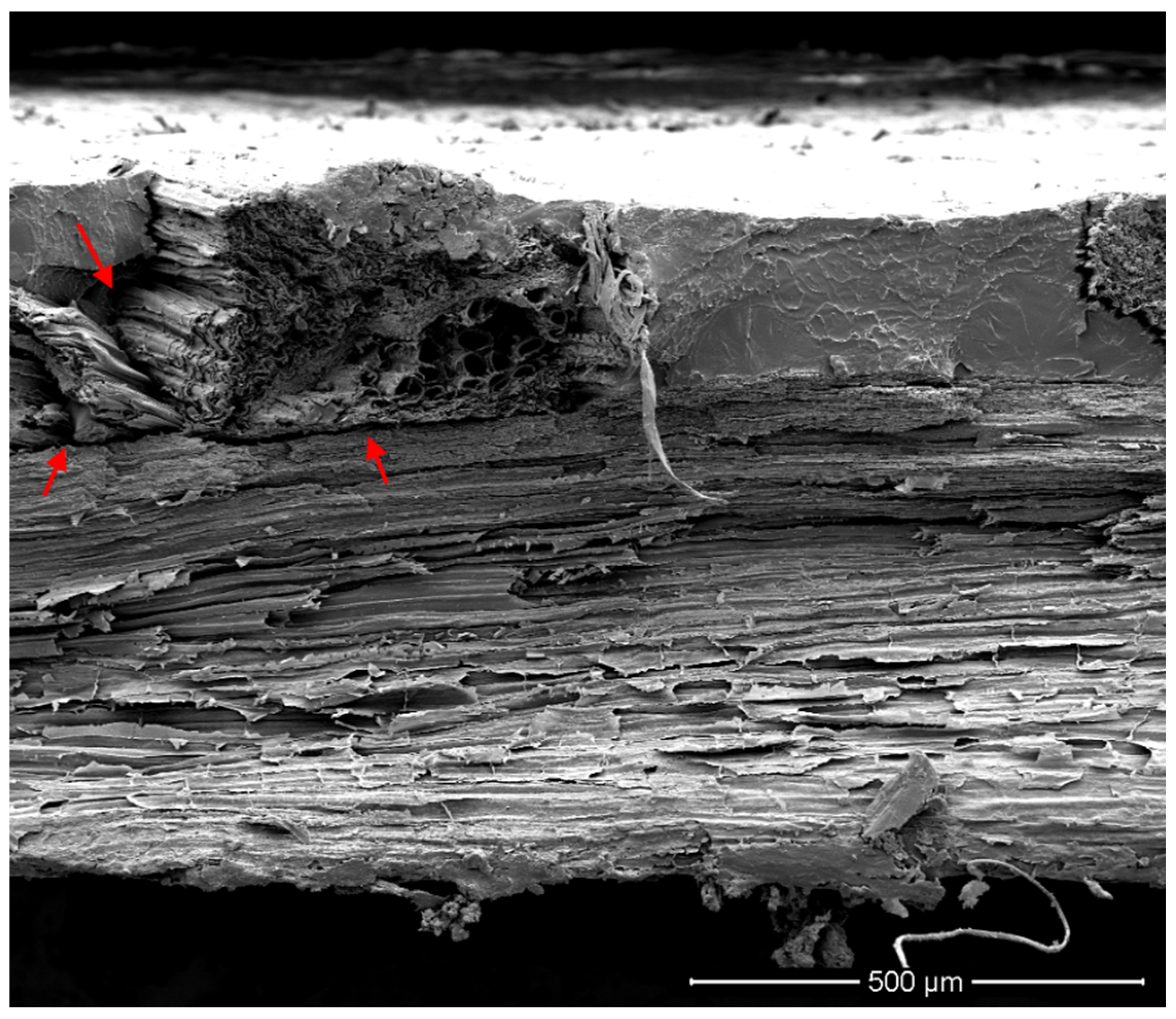
The above observations are corroborated by the SEM micrograph of the fracture surface of RANDOM composites (
Figure 6), which shows the fracture surface of the fiber bundle transversally oriented to the loading direction. Failures occur by transverse shearing of the fiber bundles and inter-fiber shearing:
i.e., the shear stresses overcome inter-fiber frictional forces, leading to the separation of fiber bundles.
Moreover, the same micrograph evidences that the random placement of the fibers within the PLA matrix can lead to their overlapping. This prevents the PLA from properly wetting the fiber surfaces, thus creating some matrix-poor areas, as indicated by red arrows in
Figure 6. Probably, the presence of these voids also contributes to the decrease of the tensile strength of RANDOM composites.
Figure 6.
SEM micrographs of the fracture surface of the RANDOM composite. Red arrows indicate matrix-poor areas.
Figure 6.
SEM micrographs of the fracture surface of the RANDOM composite. Red arrows indicate matrix-poor areas.
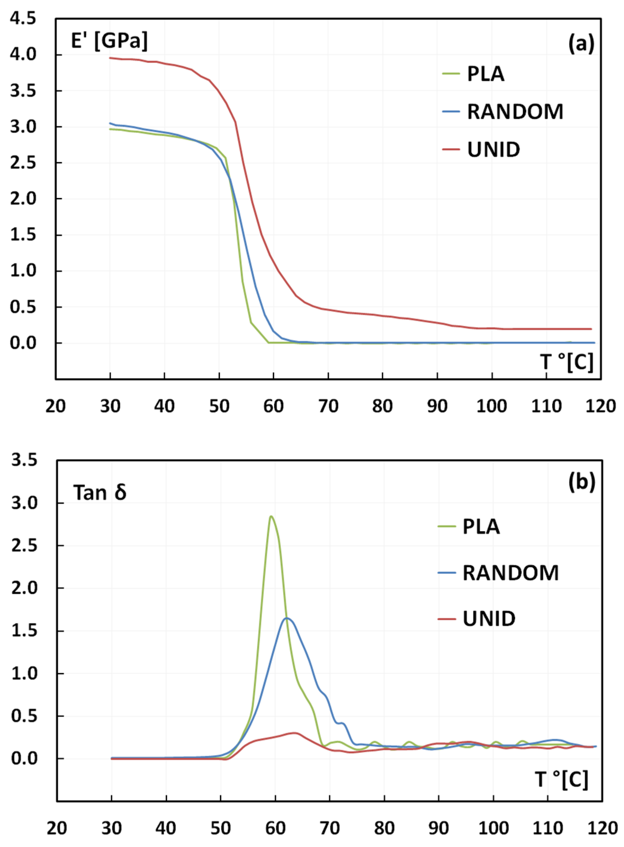
As concerns the dynamic mechanical analysis (DMA), the temperature curves of the storage modulus (
E’) and of the loss factor (tan delta) are shown in
Figure 7. The storage modulus of the UNID composites at room temperature is higher than that of the PLA matrix, because of the reinforcement effect of the aligned artichoke fibers (
Figure 7a). The other way around, the storage modulus of the RANDOM composites is quite similar to that of neat PLA. These data are in agreement with the static tensile results since, as discussed above: the fibers disposed along the load direction reinforce the PLA matrix better in comparison with the random arrangement.
As shown in
Figure 7a, the storage modulus decreases by increasing the temperature for all of the samples, with a significant drop in the range between 50 and 65 °C. Moreover, it is possible to note that the fibers’ placement also influences the softening temperature of the samples. In particular, the drop of E’ occurs at higher temperatures for the UNID composites if compared to the RANDOM composites and the neat PLA, both showing this drop at quite similar temperatures. These results suggest that the unidirectional placement of the fibers implies an extension of the working temperature range of the neat PLA matrix.
Figure 7.
Temperature dependence of (a) storage modulus E’ and (b) tan delta.
Figure 7.
Temperature dependence of (a) storage modulus E’ and (b) tan delta.
Figure 7b shows tan delta factor for neat PLA and its composites as a function of temperature. Incorporation of fibers in a polymeric matrix affects the damping behavior of the composites, which is due both to shear stress concentrations at the fiber-matrix interfaces and to the viscoelastic energy dissipation in the matrix [
19,
20]. Hence, it depends on the fiber-matrix adhesion:
i.e., a weak fiber-matrix adhesion leads to higher values of tan delta [
19,
21], while a good fiber-matrix adhesion limits the mobility of the polymer chains, thus reducing the damping. In particular, low damping means that the composite has good load-bearing capacity.
As reported in
Figure 7b, neat PLA shows a sharp and intense peak, thus indicating no restriction to the macromolecule chain motion. On the contrary, the presence of artichoke fibers hinders the chain mobility, resulting in a broader and larger peak for both the composites,
i.e., UNID and RANDOM. This behavior can be attributed to the good fiber-matrix adhesion, as suggested by the tensile results and confirmed by SEM micrographs. More in detail, UNID composites clearly show a broader and lower tan delta peak than RANDOM ones. This different behavior cannot be addressed by changes in fiber-matrix adhesion, which, as already discussed, is not affected by the arrangement of artichoke fibers within the PLA matrix. On the contrary, the different shape of the tan delta peak can be explained taking into account the random placement of the fibers within the PLA matrix. Indeed, this arrangement leads to the overlapping of the fibers, thus creating some matrix-poor areas, as previously evidenced by SEM micrographs. These zones can favor the PLA chain mobility, thus justifying the higher damping shown by RANDOM composites rather than UNID ones.
The glass transition temperature (
Tg), evaluated as the temperature at which the damping [
19,
22] attains its maximum value, is influenced by the presence of artichoke fibers in the PLA matrix. In particular, the
Tg increases from 59 °C to 61.5 °C and 64 °C for RANDOM and UNID composites, respectively. Again, this trend can be associated with the decreased mobility of the matrix chains, due to the presence of the artichoke fibers [
23].
3.2. Hill’s Method for Tensile Modulus Prediction
Hill’s method was used to calculate Young’s moduli of the PLA composites reinforced with artichoke fibers, with the aim to compare these values with the experimental ones.
Hill’s method refers to the rule of mixtures. In particular, for unidirectionally-reinforced composites, the following equations can be used to evaluate the longitudinal (
EL) and transverse (
ET) moduli, respectively:
where
Ef and
Em are respectively Young’s moduli of the fiber and matrix;
νf and
νm are the volume fractions of the fiber and matrix.
The experimental tensile modulus of PLA matrix (Em) is equal to 3.18 GPa. The tensile modulus of the artichoke fibers (Ef), determined by performing tensile tests on dried long fibers, is equal to 19.7 GPa. The fiber volume fraction (νf), evaluated considering the fiber weigh fraction (i.e., 10% for both composites) and the apparent densities of the PLA matrix and of the artichoke fiber, is equal to 0.081.
For UNID composites, the experimental value of the tensile modulus has to be compared to the theoretical value
EL. On the other hand, Hill’s method allows one to calculate the theoretical Young’s modulus for random fiber-reinforced lamina (
i.e., RANDOM composites) as follows:
It is possible to demonstrate that EL(νf) represents an upper bound in ideal conditions (i.e., perfect bonding, homogenous fiber and matrix, lack of voids), while ET(νf) is a lower bound.
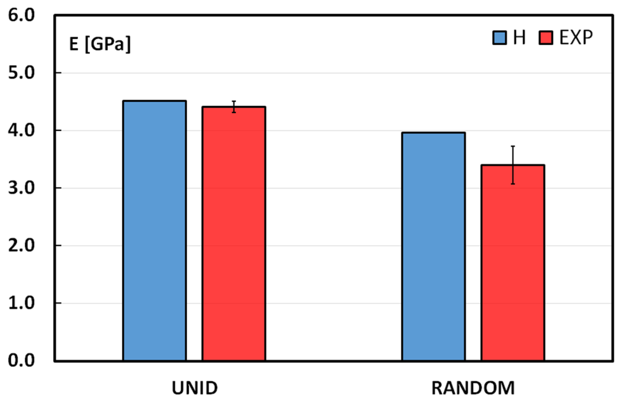
In
Figure 8, a comparison between the experimental and theoretical values of Young’s moduli for UNID and RANDOM composites is shown.
Figure 8.
Comparison between Hill (H) and experimental data (EXP) for tensile moduli.
Figure 8.
Comparison between Hill (H) and experimental data (EXP) for tensile moduli.
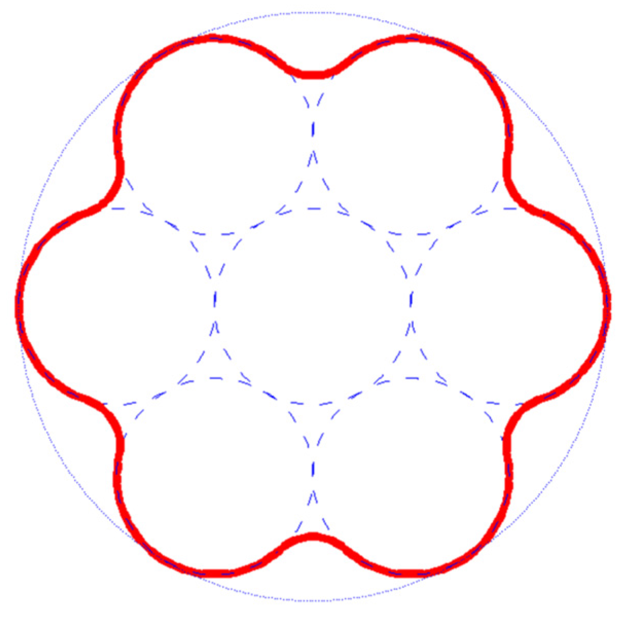
Regarding the UNID composites, even if the raw materials are far from the ideal conditions, the experimental value is quite close to the theoretical one. This good behavior could be explained taking into account the morphology of the single fiber. A simplified representation of the artichoke fiber cross-section, which shows the packing of several cylindrical elementary fibers in a bundle or technical fiber, is reported in
Figure 9.
It is important to note that, taking into account the good fiber/matrix adhesion evidenced by SEM analysis, the bonding surface (highlighted in red in
Figure 9) results in being larger than the ideal cylindrical one, thus reducing the fiber-matrix interface shear stresses. This is confirmed by the absence of the pull-out mechanism during tensile tests, as widely discussed in the previous section of this work. On the other hand, the surface shape of a single fiber may promote mechanical interlocking effects, so increasing the shear stress capability of the fiber-matrix interface.
Figure 9.
Simplified representation of the cross-section of artichoke fiber.
Figure 9.
Simplified representation of the cross-section of artichoke fiber.
As concerns the RANDOM composites, Hill’s method overestimates the experimental values. This is probably due to the fibers overlapping. As discussed above, this arrangement limits the PLA flow during the composite preparation, so the fiber-matrix stress transfer is not guaranteed in some matrix-poor areas: i.e., artichoke fibers produce a low level of reinforcement.


