1. Introduction
Lignite, as an energy resource, still has a significant share in the energy mix of many countries, in Europe and worldwide. It is also expected to make a large contribution to the sustainable and independent energy future of these countries, in the transition period until the renewable resources’ unsolved issues find mature solutions, as backup for periods of low renewable energy output, and as more nuclear power plants are scheduled for decommissioning over time.
Reducing cost and increasing production and efficiency are requested for a sustainable lignite production. To achieve this, optimization of production is necessary, and this can only be achieved by the modernization, revitalization, and maintenance of mining equipment.
A bucket wheel excavator (BWE), along with its transport system (conveyors), is a part of the continuous mining systems that operate in open pit mining. Due to the high costs of its operation, it is important to have it operate flawlessly and avoid unexpected stoppages caused by defects. In order to plan the BWE’s operation for optimal production, it is also important to minimize the maintenance time. Maintenance, including fatigue analysis, needs to be conducted periodically due to the structural damage that may be induced by the harsh conditions that BWEs operate under.
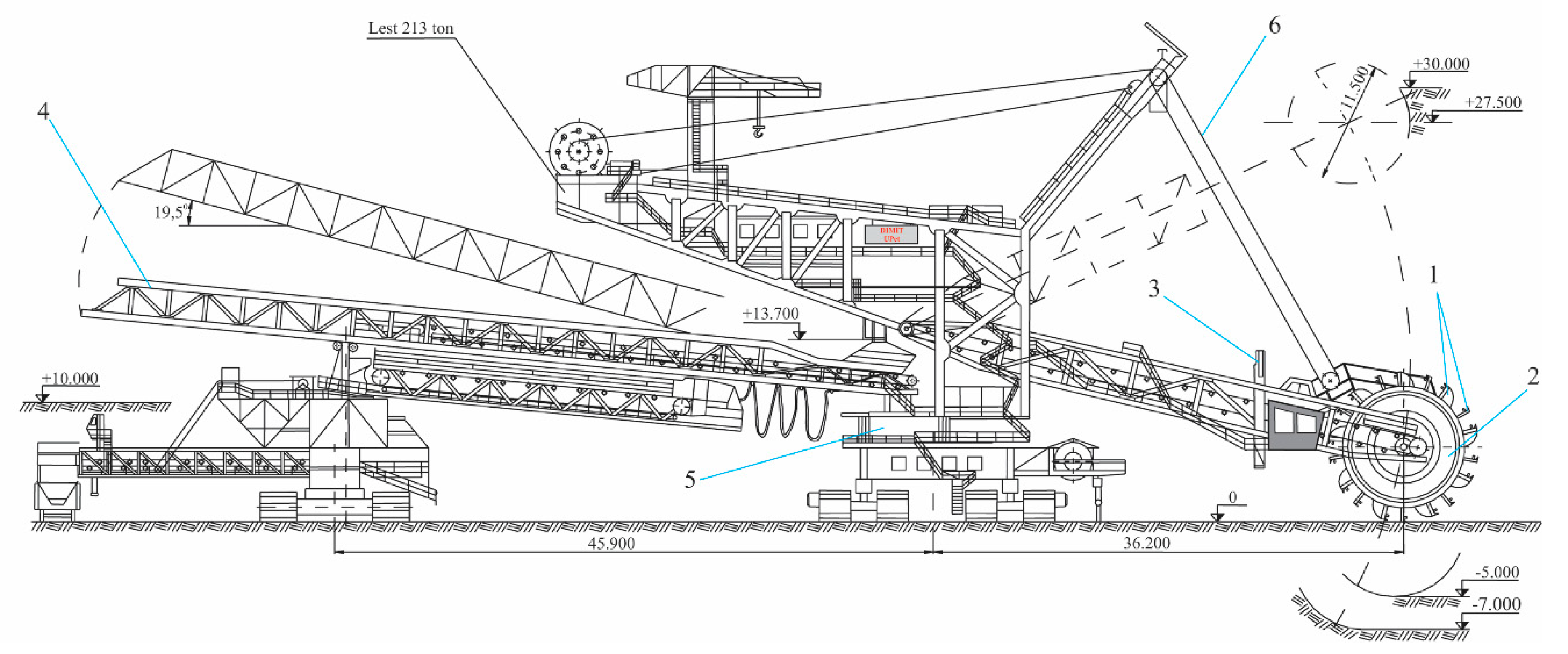
The ERc 1400-30/7 bucket wheel excavator is a machine with continuous operation that excavates the working face with the help of the buckets installed on its rotor. At the same time, it transfers the excavated material to the main conveyor with the help of the conveyor belts installed on its boom (
Figure 1). The operating equipment is the bucket wheel, which performs a rotation movement in the vertical plane and, with the help of the boom, a horizontal slewing movement and a vertical raising–lowering movement [
1,
2].
This paper proposes a new approach, based on a virtual model of the BWE’s boom, to analyzing the time response to the loads generated during the excavation process.
In [
3], an analysis of the vibrations at the level of a BWE’s boom was carried out by measuring the accelerations resulting from the sequence: Starting the bucket wheel, starting the conveyor belt, and stopping both drives. In [
4], vibration measurements were made while the bucket wheel was suspended by hoisting ropes without contact with the working face and while the bucket wheel was borne by the working face. In both scenarios, an impulsive load was simulated by shooting a rope on which a weight was suspended onto the wheel.
In this paper, we analyze the time response of the ERc 1400-30/7 excavator’s boom with the bucket wheel under the action of the excavation forces.
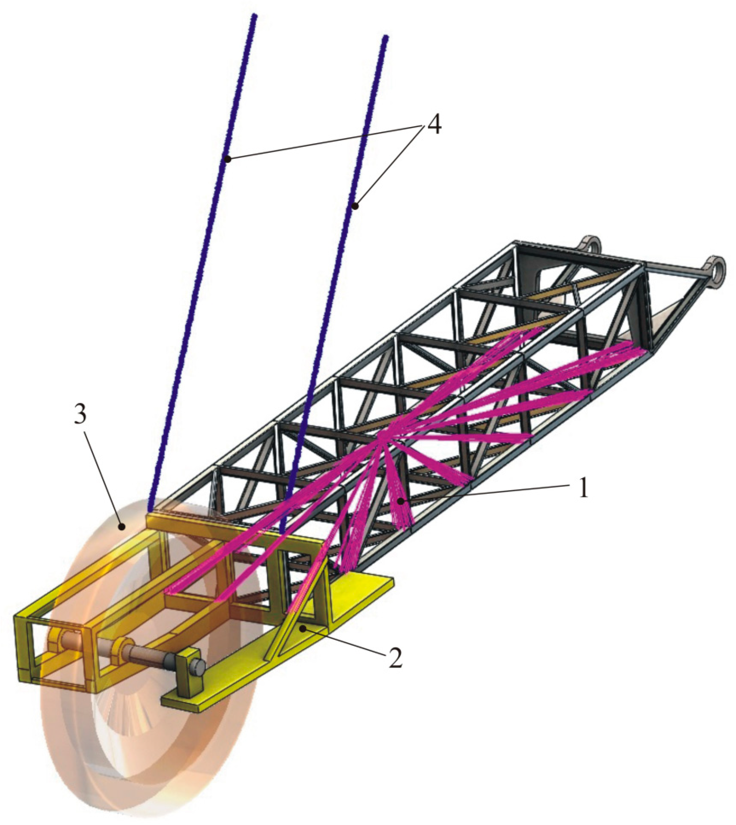
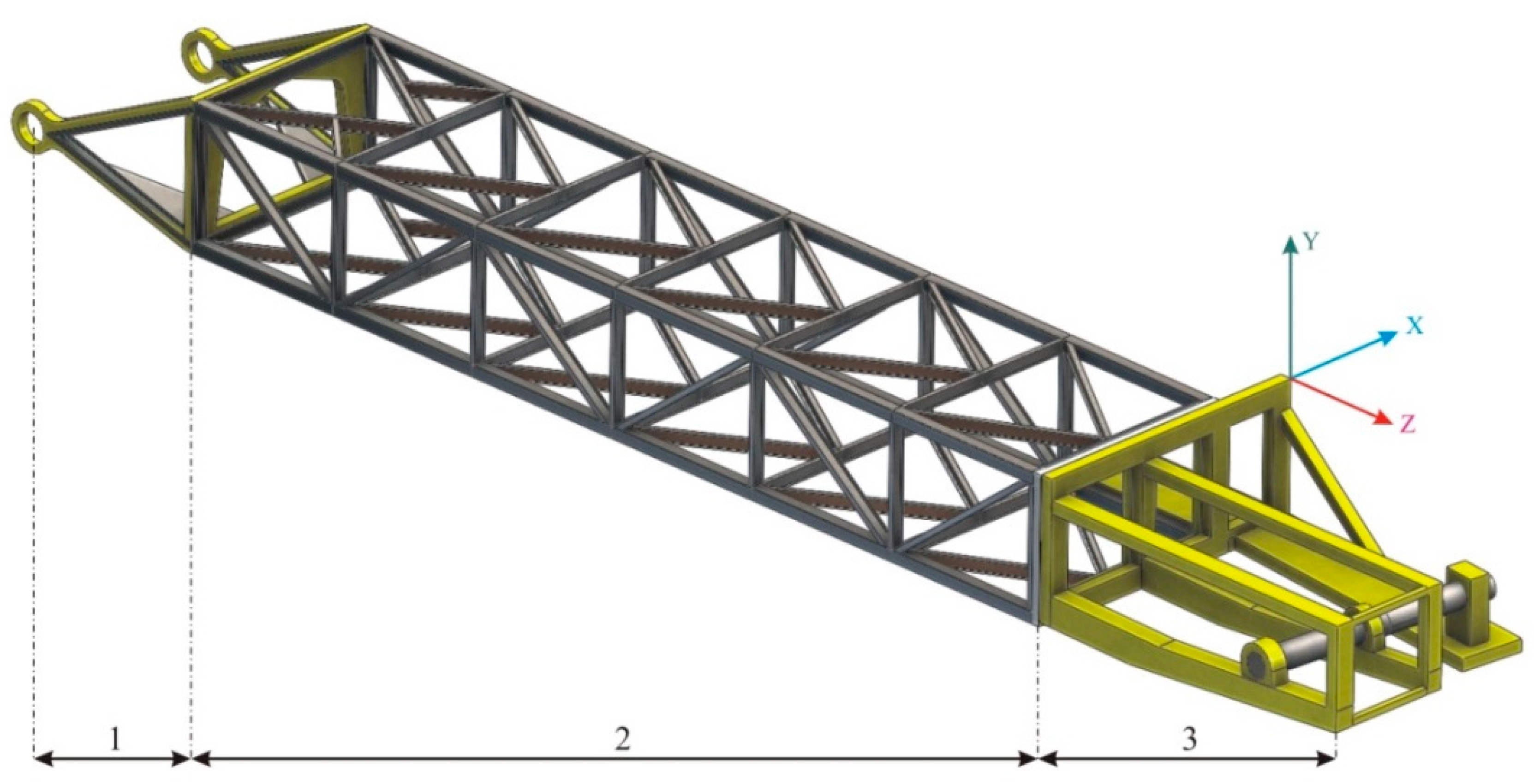
The boom of the ERc 1400-30/7 bucket wheel excavator is a spatial, load-bearing structure that can be divided into three sections (
Figure 2):
The joint section between the boom and the structure, which allows for both vertical and horizontal movement;
The intermediate section on which the conveyor belt is mounted for the discharge of the excavated material; and
The bucket wheel support section on which the drive mechanisms, as well as the boom hoist cable attachment device, are mounted [
5].
During the excavation process, the energy consumption at the level of the bucket wheel has two major components:
Between these two energy consumption components, the energy necessary for cutting the material is predominant, representing 60%–90% [
6] or 70%–90%, according to [
7], of the energy necessary to operate the bucket wheel. Thus, only those forces that correspond to the actual cutting were taken into consideration in the simulation.
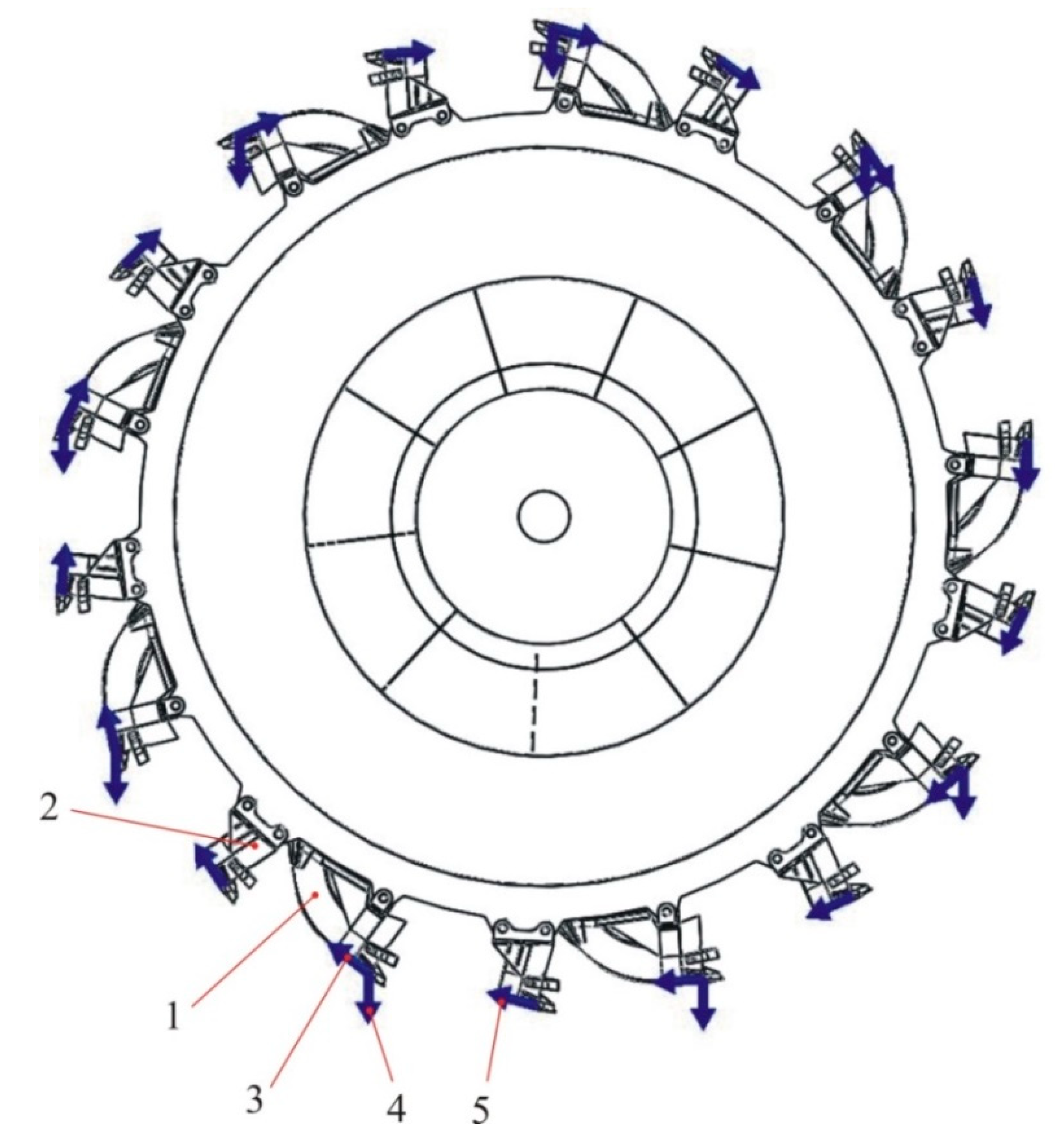
The rotor of the analyzed BWE is equipped with nine cutting–loading buckets and nine cutting buckets (
Figure 3).
On each of these buckets, during excavation, the following forces are acting: The cutting forces, the lateral forces, the advance forces, and the forces corresponding to the weight of the material. Of these, two forces have a periodic character, and represent the input data [
8] for the simulation:
The cutting forces, which are tangential to the circle described by the cutting edges and act both on the cutter–loader and the cutter buckets (
Figure 4a,b); and
Forces corresponding to the weight of the material, the action of which occurs as soon as a cutter–loader bucket enters the excavation process until the material in this bucket is discharged to the conveyor in the boom (
Figure 5). Here, we highlight the time intervals t
1 corresponding to the loading of the cut material, t
2 corresponding to the lifting of the loaded bucket up to the discharge level, and t
3 corresponding to the material’s discharge on the conveyor [
8,
9].
The variation in forces shown in
Figure 4a,b and
Figure 5 corresponds to a single cutter–loader bucket and cutter bucket, respectively, and are plotted for two complete rotations of the bucket wheel, during which each bucket performs cutting twice.
The offset time that occurs between two successive curves in
Figure 4a,b, respectively, is given by the rotation speed of the bucket wheel. For the model of the ERc 1400-30/7 BWE, the speed is 4.33 rpm [
2], which leads to an offset time of 13.86 s between two successive cuts of the same bucket. The time gap between the diagrams in
Figure 4a,b corresponds to an angular distance between two successive buckets (one cutter and one cutter–loader) of
during a 0.77 s time interval. The weight of the loaded material only refers to the cutter–loader buckets at a discharge rate of 39 buckets/min, which means an identical gap of 13.86 s. Only the duration of the process is longer, as to the time of the cut, t
1 the lifting and discharge times (t
2 and t
3) are added. By overlapping the three forces (considering the offset as shown) and reducing them to the bucket wheel’s shaft, the time variation of the resultant force on the shaft is obtained.
The resultant force at the shaft of the bucket wheel represents an excitation force and is the main source of vibration of the boom. These vibrations are transmitted through the boom to the entire structure of the BWE.
2. The Model of the Boom
Based on the constructive characteristics of the ERc 1400-30/7 BWE, we developed a virtual model of the bucket wheel’s boom. This model will be used to analyze the time response to the loads generated during the excavation process.
The main static loads (mass forces) to which the boom and its elements are subjected are presented in
Table 1, where the type of SolidWorks
® Simulation specific load is also defined (
Figure 6) [
10]. It is known that both the conveyor belt mounted on the boom and its kinematic drive chain also generate vibrations. The model adopted in this paper only considers the static effect of their presence according to
Table 1, thus highlighting the dynamic response in time of the boom structure under the action of the excavation forces. The values given in
Table 1 are based on the manufacturer’s specifications [
2].
Based on the constructive characteristics given by the producer [
2], this BWE is equipped with 10 hoisting cables, which have a double role: Vertical positioning of the boom and damping of the boom structure vibrations during excavation. Each cable has an elasticity constant of approximately 7 × 10
6 N/m, so the 10 parallel cables were modelled using two spring-type static loads (a SolidWorks
® software feature) of an equivalent 3.5 × 10
7 N/m each.
3. The Dynamic Regime of Time Response during Excavation
Analyzing a system in the time domain requires a very large computation capacity. For this reason, a solution to solve vibration problems is the method of modal analysis by superposition. Besides the frequency, the percentage of the masses that participate, and the shape of the structure deformation, this analysis is associated with the direction of the deformation as a function of elasticity. Thus, an object in a certain mode of vibration can be represented by a system with a single degree of freedom (DOF) with mass, elasticity, and deformation directions that correspond to the properties of the considered mode. We can represent a system with three oscillators with one DOF each, regardless of its complexity.
Figure 7 shows the principle of the modal analysis by superposition method. This is used in finite elements vibration analysis of linear systems [
11].
The dynamic analysis of the time response implies that the load applied to the structure is an explicit function of time, mass, and damping properties. The characteristic equation is:
where
is the mass matrix;
is the damping matrix;
is the elasticity matrix;
is the vector of nodal loads, expressed as a function of time; and
is the unknown vector of nodal displacements.
The results of the time response analysis will refer to both the time during load and the free vibration after the load has been removed, and will show the deformations and accelerations corresponding to the X, Y, and Z directions (
Figure 2).
We considered the global damping to be variable by frequency [
12,
13]. Its imposed values, as well as the corresponding modal frequencies, are presented in
Table 2. According to [
14], the 15 analyzed modes are sufficient because the cumulative effective mass participation factor (CEMPF) in the X and Y directions, starting with mode 11, exceeds 80% and remains constant for all directions. Directions X and Y are actually expected to present vibration-induced stresses due to the excavation process and also due to the constructive structure of the boom. According to [
4], the natural frequencies of a BWE are low, and the authors suggested that frequencies greater than 20 Hz be filtered during the vibration measurement process. Based on these theoretical and practical considerations, the number of modes considered was limited to 15.
The exciting force is applied to the surface of the bucket wheel’s shaft, as a uniformly distributed force on its support surface (
Figure 8), and is a function of time (
Figure 9). Here, we present the variation in the force at the bucket wheel’s shaft when the excavated material is homogeneous.
The properties of the material considered in the model are based on research conducted by the department in the past, when experimental testing was conducted on actual rock samples taken from open-pit mines [
15]. In order to simulate the response in time corresponding to the free vibrations, the force action ceases at a time of t = 15 s.
The diagrams in
Figure 9 and
Figure 10 represent forces generated by the excavation process (cutting and lifting of the material). Their frequency is determined by the angular rotation speed of the bucket wheel and the number of buckets (both cutter and cutter–loader buckets) fitted to the bucket wheel, while their magnitude is given by the hardness of the excavated material [
8]. To determine the time response of the BWE’s boom, a Workflow Sensitive type virtual sensor was placed exactly at the origin of the coordinate system shown in
Figure 2.
If, during the excavation of homogenous material, a hard material inclusion (boulder) appears, the variation of the vibration-generating force is shown as in
Figure 10 [
8].
3.1. Dynamic Time Response Analysis under Normal Operating Conditions
Figure 11,
Figure 12 and
Figure 13 represent the variation in time of the deformation of the BWE’s boom structure for the X, Y, and Z directions when a force variable, as shown in
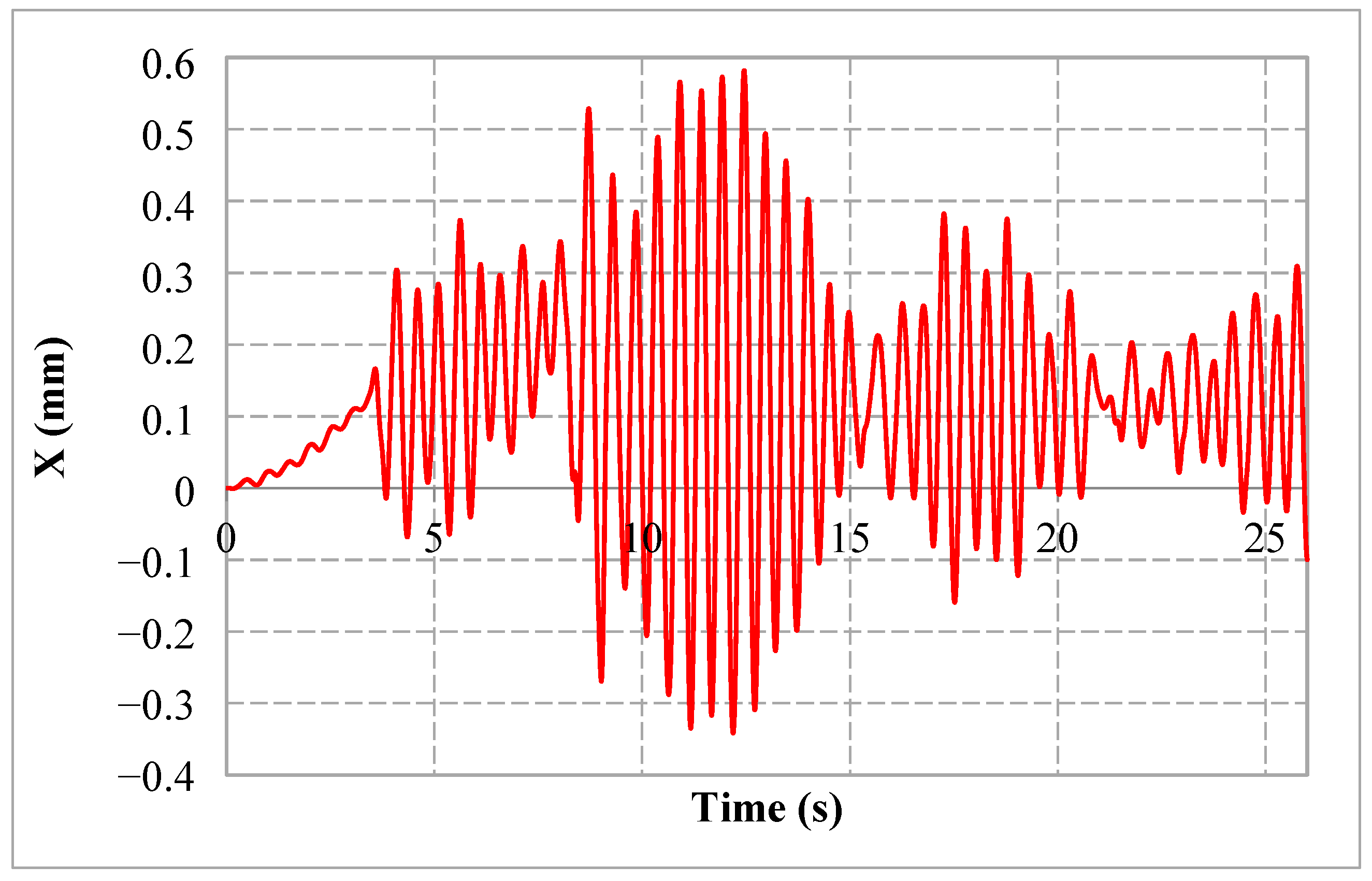
Figure 9, is applied over time. For all considered directions, three distinct parts are visible in the graphs:
The first part corresponds to the time interval (0 ... 4.5) seconds and represents a transient regime due to the start of the excavation process;
The second part corresponds to the time interval (4.5 ... 15) seconds and represents the permanent response of the boom structure to the action of the force; and
The third part corresponds to the free vibration of the structure after the force is stopped at 15 s. It is noticeable that the vibration is damped and the amplitude of the vibrations to the equilibrium position tends to 0.
X-axis oscillations are asymmetric with respect to the balance position of the bucket wheel’s boom. This is due to the eccentric position of the bucket wheel and the angle of its shaft in relation to the X-axis. The values of these deformations in relation to the equilibrium position vary between +0.418 mm and −0.213 mm.
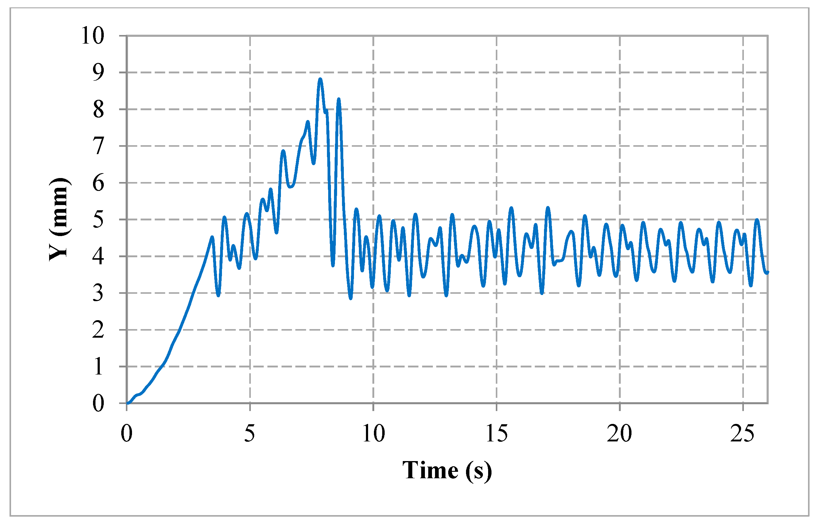
The oscillations have the highest value on the Y-axis, where the oscillations during the permanent regime vary around 4.1 mm of deformation, with the maximum amplitude of 1.1 mm.
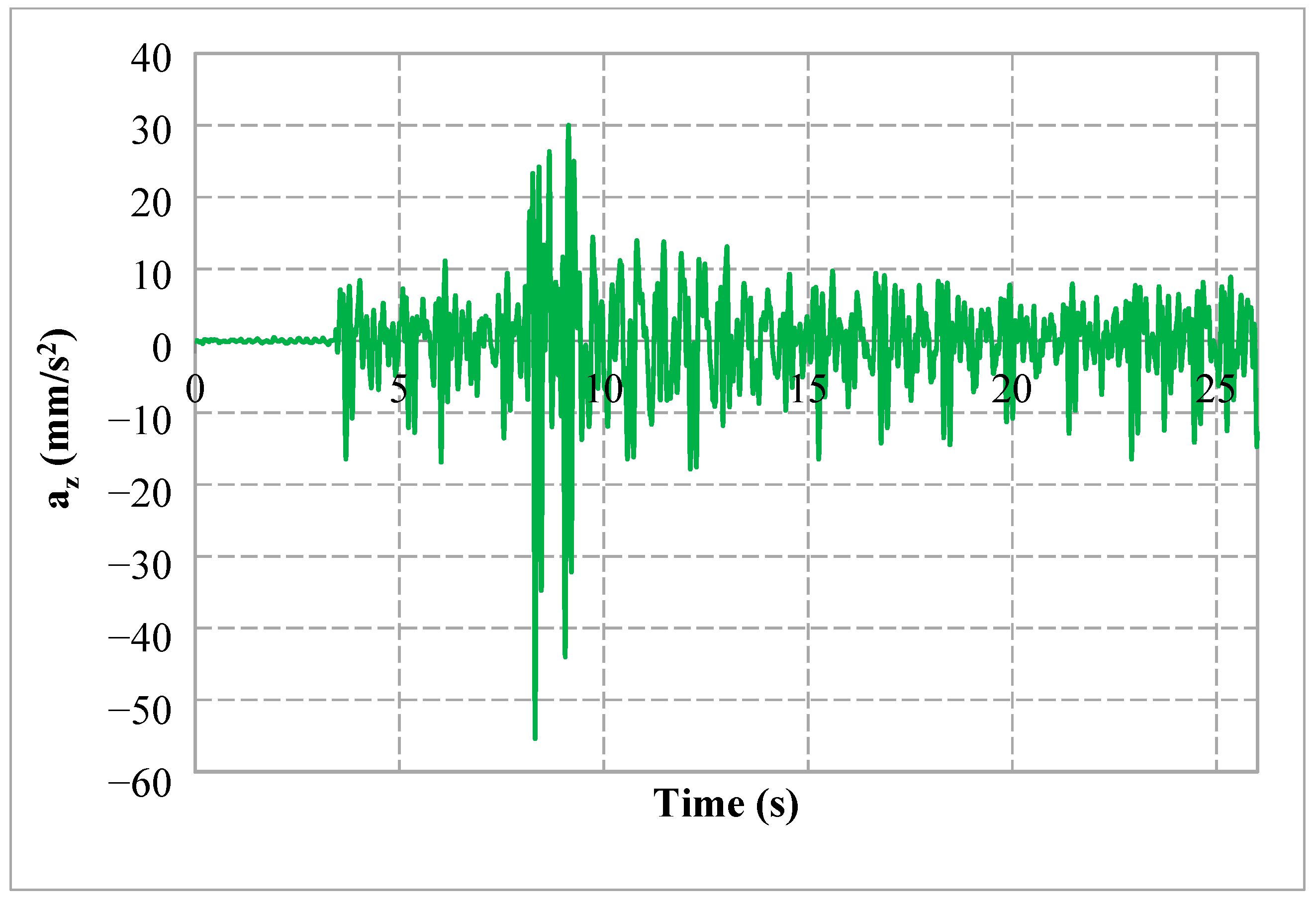
For the Z-axis, the oscillations obtained from the simulation are similar in shape to those corresponding to the Y direction, the oscillations being around 0.09 mm, with the maximum amplitude of 0.053 mm.
Figure 14,
Figure 15 and
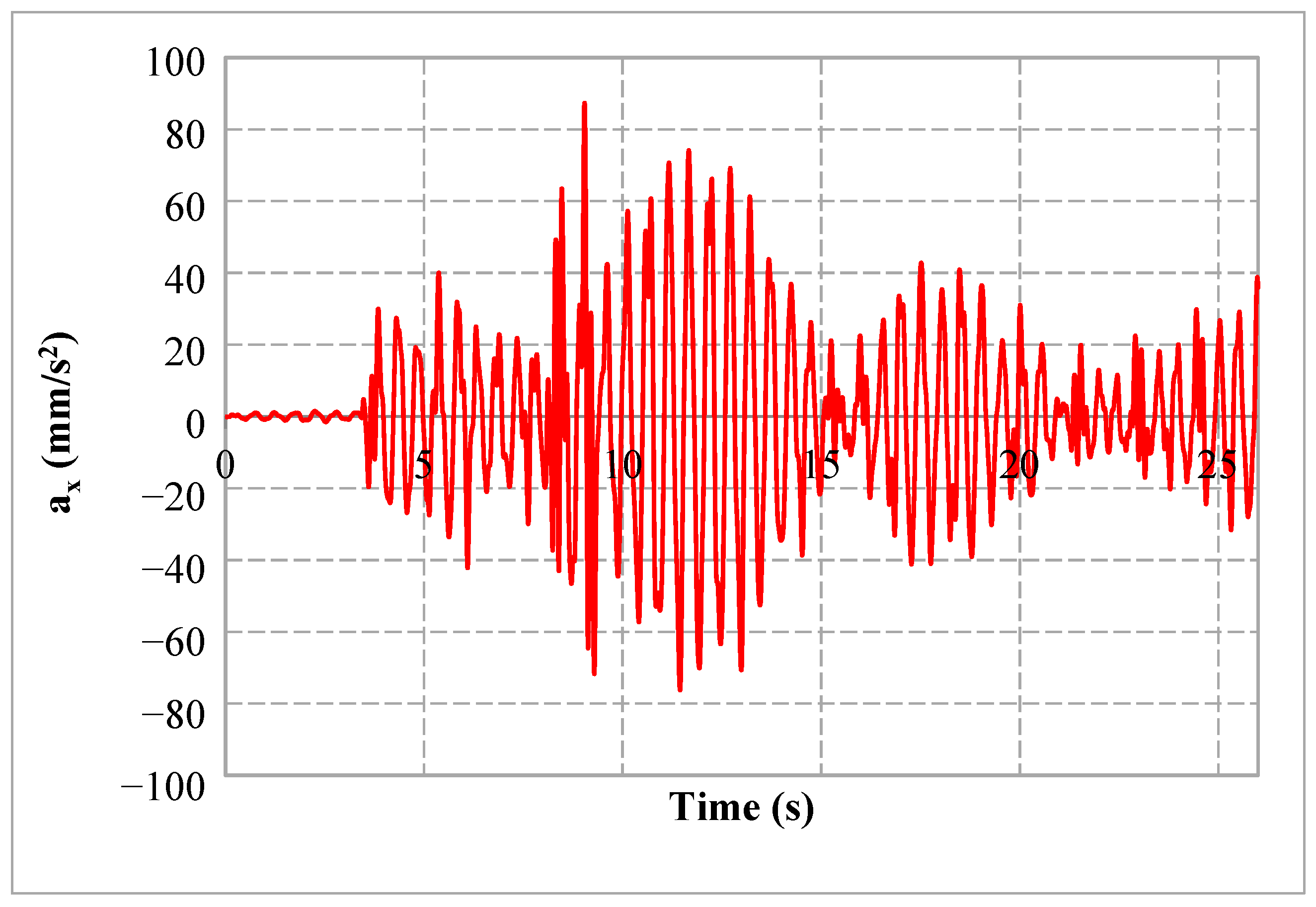
Figure 16 show the variation in time of the accelerations of the BWE’s boom structure for the X, Y, and Z directions.
As in the case of the deformations previously analyzed for the X, Y, and Z directions, it is visible that accelerations tend to 0 after the excitation force disappears. The highest values are obtained for the Y direction.
3.2. Dynamic Time Response Analysis for Shock Load
Figure 17,
Figure 18 and
Figure 19 represent the variation over time in the deformation of the BWE’s boom structure for the X, Y, and Z directions when, as shown in
Figure 10, a shock-type load is applied over time. It can be seen for all directions that the sudden occurrence of hard material inclusions in the homogenous material of the excavated face produces a transient regime, after which the oscillations stabilize in a permanent regime.
For this scenario, too, the direction for which the oscillations have the highest value is Y. The maximum amplitude of the oscillation in this case is 8.7 mm. For the Z direction, the maximum amplitude of the oscillation is 0.21 mm, and for the X direction it is 0.58 mm, as compared to the equilibrium position.
Figure 20,
Figure 21 and
Figure 22 show the variation in time of the accelerations of the excavator’s boom structure for the X, Y, and Z directions in the case of a shock load. In transient mode, the maximum acceleration value is obtained on the Y direction and is 495 mm/s
2.
4. Discussion
A boom model was created for an ERc 1400-30/7 bucket wheel excavator, and was used to analyze the time response of the loads generated by the bucket wheel during excavation. We defined a mathematical model of the resultant of the excavation forces—which are the main source of vibration of the boom structure—and we determined the static loads acting on the boom of the BWE.
We conducted a dynamic analysis of the time response of the bucket wheel excavator’s boom for a global damping variation depending on frequency in two scenarios: Excavating homogenous material and the sudden occurrence of a hard material inclusion in the homogenous material (shock load). For all the analyzed situations, it was found that the time response to the action of the excavation force is characterized by the following aspects:
Transient periods caused by the beginning of the excavation process;
Transient periods caused by the sudden occurrence of hard formation (boulder) in the excavated face; and
Permanent regimes corresponding to the excavation of the homogeneous material.
The free vibrations resulting after the force had stopped became null over time. This period of time was determined by the global damping that was imposed on the model under consideration. Higher damping resulted in a shorter transient period, a faster cancellation of the free vibrations, and an increase in acceleration values for all directions.
The model proposed can be used for different types of BWEs as well as for the analysis of lattice (truss) beam structures, which are subjected to variable loads over time during their operation.
In practice, the expression of vibrations in terms of deformations is suitable for low frequencies, and the expression of vibrations in terms of acceleration is appropriate for high frequencies. The model adopted and presented in this paper allows for a good approximation of both these approaches—deformations or accelerations—and it can be adapted quickly for different types of BWEs.
The results highlight the role of damping in the evaluation of the time response of the excavator’s boom structure. Adopting a variable damping depending on the frequency (and the number of the mode) leads to results that are comparable to measurements made on such machines during actual operation [
16]. We underline that the analysis and simulation were only performed on the time response of the excavator’s boom structure.
The concordance between the simulation results and acceleration measurements performed in situ on the same type of BWE highlights the validity of the adopted model. The simplifications of the model as compared to the real equipment do not lead to a distortion of the results obtained by simulation.
This aspect allows for the use of this model in future research and fatigue studies of the elements of the arm. Fatigue analysis needs to be conducted periodically, at the request of the companies operating BWEs, in view of planning the maintenance of these machines. This method can also be adapted relatively easily and used for different bucket wheel excavators.

 ,
, 


