Article

Will Wind–Sand Activity Bury the Opencut Tunnel along the Linhe–Ceke Railway, China?

Key Laboratory of Aeolian Physics and Desertification Control Engineering from Inner Mongolia Autonomous Region, College of Desert Control Science and Engineering, Inner Mongolia Agricultural University, 29 Erdos East Street, Hohhot 010018, China
*
Author to whom correspondence should be addressed.
Sustainability 2022, 14(18), 11684; https://doi.org/10.3390/su141811684
Submission received: 16 August 2022 / Revised: 4 September 2022 / Accepted: 13 September 2022 / Published: 17 September 2022

Abstract

:
The opencut tunnel is a kind of linear arch construction and a new linear sand-prevention structure. In order to clarify the wind-proof mechanism of the opencut tunnel, this paper seeks to answer the question of whether the opencut tunnel of the Lin–Ce railway will be buried. In this paper, a wind tunnel experiment combined with field investigation and testing is used to systematically study the mechanism of wind and sand resistance in an opencut tunnel, and it is verified whether the sand burial of the opencut tunnel is possible. The results show that the airflow greater than 0.7 times of the height is in a state of acceleration and uplift, and no sand-filling phenomenon occurs at the ventilation vent at the top of the opencut tunnel. More than 85% of the sediment transport on the windward side was within the height of 0–10 cm, and 80% on the leeward side was concentrated in the height of 30–70 cm; the greater the angle between the opencut tunnel and the wind direction, the higher the potential of wind and sand resistance. In the past 20 years, no mass accumulation of shifting sand occurred along the opencut tunnel. Furthermore, the shifting sand could not bury the opencut tunnel in the small-scale time range. Wind-field characteristics determine angle between the opencut tunnel and wind direction as 75°−90°, setting the optimal scope of protection. However, different angles can effectively prevent and control sand flow hazards in railways, ensuring smooth railway operation.

1. Introduction

Currently, most of the in-service railway lines crossing deserts and arid regions are located in northwestern China. Approximately 18,000 km of railway lines face sandstorm hazards or potential sandstorm hazards, which is the longest railway network (in the world) crossing deserts [1]. For example, the main railways affected are the Qinghai–Tibet railway, Lan–Xin railway, Bao–Lan railway, Lin–Ce railway and some other trunk lines [2,3,4]. With the development of the western region of China and the acceleration in the construction of national defense transportation trunk lines, the problem of sandstorms faced by railways has become increasingly prominent. The length of some sections affected by sandstorms is up to 30%, seriously affecting the safety of trains [5]; therefore, effectively ensuring the safe operation of the railways in sandstorm areas has become an urgent problem.
The railway equipment being polished by wind erosion, and damage to the railway vehicle [6] and infrastructure [7], power and communication signals and other driving facilities [8,9,10], is in direct contact with the buried bed and rail [11,12]. The uneven track bed can also cause the triangle pit and low joint phenomenon, and the track bed sand causes train derailment and slow transportation [13,14]. These events increase the cost of line operation and maintenance and restrict the performance of railway facilities. Various sand blocking and stabilizing measures have been adopted in the railway project to resist sandstorms [15,16,17,18], such as using straw, nylon nets, geotextiles, salwillow, PLA (polylactic acid), porous fences, windproof roadbed walls, sand retaining walls, windproof bridge shelters, windproof excavation tunnels, etc. [19,20,21,22,23]. To further improve the wind protection engineering measures, a sand-control engineering system has been established at the windward side of sandstorm-prone areas [24,25].
When selecting the route for the Linhe–Ceke railway line, the line design unit chose to detour along the south side of the nature reserve to the Badain Jaran desert to protect the Populus euphractica forest of the Ejina national nature reserve and avoid the destruction of the P. euphractica desert riparian forest. Although the detour protected the P. euphractica forest to the greatest extent, it meant that the railway passed through a 10 km mobile dune area on the northwest margin of the Badain Jaran desert. To prevent sandstorm hazards after the completion of this section, the design unit compared several types of construction, and finally completed an opencut tunnel railway of 8.08 km in the densest area of mobile dunes (Figure 1). However, the line seems to be one of the most vulnerable ones. In the first year of operation, over 10.000 workers were mobilized and CNY 71 million was spent on windblown sand-induced maintenance; service was suspended for two months in the spring of 2010; in the first 36 days after passenger service was introduced in November 2010, sand storms buried the track for 27 days and caused 51 service disruptions [26]. Therefore, the design organization introduced the opencut tunnel to ensure the safe operation of the railway, and this was the first time that the opencut tunnel was applied to railways in China
The opencut tunnel, as a new type of linear sand-control measure compared with traditional engineering sand-control measures, has the basic characteristics of a sand-control wall. In addition, in the area of serious sand damage, especially when the railway needs to cross the desert, the intervention of the opencut tunnel guarantees the safe operation of the railway. An opencut tunnel is a linear arched structure constructed in the section with serious sandstorm activity. Its interior is isolated from the sandstorm flow, thus avoiding the direct harm of sandstorm flow to the railway and locomotive. As a new linear sand-prevention measure, compared with the traditional engineering sand-prevention measures, the opencut tunnel has the basic sand-prevention characteristics of sand-retaining walls, and the characteristics of being wind-proof and of a large construction size, so that the traditional engineering sand-prevention measures of wind-prevention and sand-resistance mechanisms in the sand-prevention tunnel encountered unprecedented difficulties. Therefore, at present, there are few reports on the function principle, effective period and effect of opencut tunnels.
Owing to the particularity of sand-control tunnel structures, compared with traditional linear engineering sand-control measures, the variation characteristics of airflow on the windward and leeward sides are considerably different from the structure of the sand flow, which has become an important basis for determining whether sand is buried. Existing studies have shown that airflow has different motion characteristics at different positions on the transverse dune surface. For example, the airflow accelerates on the windward slope of the dune and forms rotating topographic flow, while on the leeward slope, it can form separated flow, reattached unbiased flow, reattached biased flow and reverse flow [27,28]. The reattachment distance of leeward airflow is closely related to morphological characteristics of dunes. The structure and transport characteristics of aeolian sand flow are influenced by transverse measures/dunes. Field measurements by Dong et al indicate that sand transport was greatest at the crest and on the windward stoss slope [29], which is similar to the results of Wiggs [30], Lancaster et al. [31] and Sauermann et al [32]. Zhang et al collected field observations of the wind profile and sand transport over a dune’s windward slope and found that the wind profile over the dune’s windward slope can be expressed as a logarithmic function and that sand transport can be expressed as an exponential function [33]. The Charnock model is further modified to give the best fitting relationship between shear velocity and roughness length [34]. However, the mechanism of sand blocking and its response to the aeolian sand environment have not been clearly explained.
Most Lin–Ce (Linhe to Ceke) railway sections are through the Ulan Buh desert, Marjorie lake, the Badain Jaran desert and the vast Gobi desert area. Sandstorms are continuous throughout the year, with variable directions, and sandstorms accumulate on both sides of the line. It is an ideal place to study the sandstorm activity of railways. Therefore, in order to better understand the characteristics of sand along the railway and the characteristics of wind resistance of opencut tunnels, using a wind tunnel simulation test, this paper studies the opencut tunnel combined with the different models of the variable field characteristics of the wind direction angle of airflow velocity, model structure and resistance characteristics of sand and the sand flow before and after sand holes oin the sand environment response. The research results can not only answer the question of whether the opencut tunnel of the Lin–Ce railway will be buried, but also clarify the wind-proof mechanism of this large-scale sand-proof measure (opencut tunnel), which can provide a reference basis and design suggestions for sand damage control of railways and highways in sandstorm areas.

2. Material and Methods

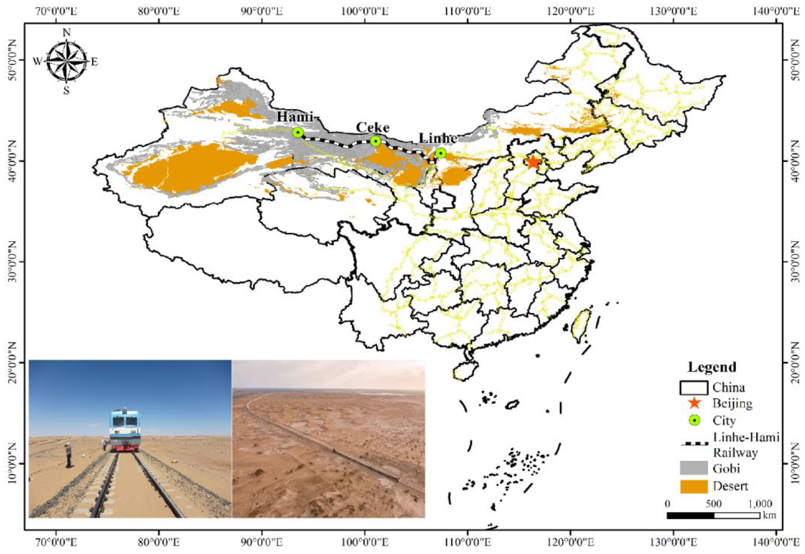
2.1. Background of Research Area

The Lin–Ce (Linhe to Ceke) railway line is located in the inland arid areas of northwest China, Inner Mongolia Autonomous Region. It is located between Bayannur city station in the east and in the west to the border with the Alxa League Ejina Ceke port. The total length of the line is 768.415 km, of which about 456 km is a sandstorm disaster area. The highest sandstorm that accumulates on the section with serious sandstorms exceeds the rail surface by 1.5 m. The natural environment along the railway is harsh, with strong winds and severe sandstorm activity. For many years (1981–2014), the average wind speed has been 4.68 m/s and the average maximum wind speed has been 9.39 m/s. The wind directions with >5-m/s wind speed were W, WNW, E and ENE, accounting for 64.11% of the overall wind frequency. All data were obtained from Ejina meteorological station and Guaizihu meteorological station near the Lin–Ce railway. The study area is rich in wind energy resources, up to 200 W/m2, and the strong wind becomes the main driving force of aeolian sand movement; the crescent dunes and sand dune chains make the influence of the study area one of the most vigorous areas in the Badain Jaran for desert sand movement.

2.2. Experiment Design and Set-Up

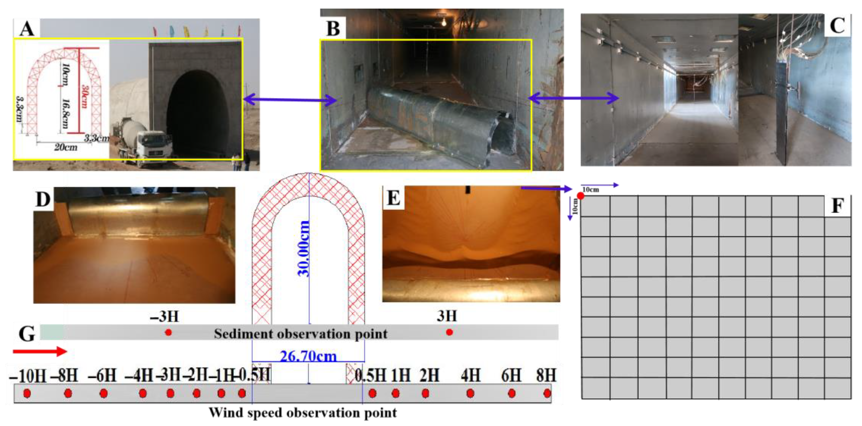
2.2.1. Wind Tunnel Introduction and Model Design

The wind tunnel experiment was carried out in Shapotou soil wind tunnel laboratory, cold and arid regions environmental and engineering research institute, Chinese academy of sciences. The length of the low-speed wind tunnel was 37.08 m, the length of the test section was 21 m, the cross section was 1.2 m × 1.2 m, the turbulence degree was less than 1‰ and the axial static pressure was gradient. The free-stream wind velocity in the wind tunnel ranged from 1.2 to 30.8 m/s.
The wind tunnel speed is calculated as [35].
v = 4.05 P p × T 293 × Δ h
where v is wind speed, P is standard atmospheric pressure (mmHg), p is local atmospheric pressure (mmHg), T is temperature (K) and Δh is pitot tube differential pressure (mmH2O).
When designing a model of a sand prevention tunnel, both the accuracy of the model size and the operability of the experiment should be considered to determine whether the model meets the requirements of wind tunnel simulation and a similarity ratio of 1:30 should be adopted. The experimental model is 100 cm long, 26.7 cm wide and 30 cm high, and the air vent at the top of the model is 10 cm × 10 cm (Figure 2).
The material of the model is iron sheet and wood, made by model welding. In order to make the model display smooth and reduce the impact, we sprayed non-slip paint on the model display. The experimental design of the wind tunnel does not involve the response of sand particle size characteristics to opencut tunnels, and the source of the sand samples does not affect the smooth implementation of the experimental scheme, nor does it affect the test accuracy and the analysis, summary and extraction of general laws. Therefore, samples of aeolian sand were taken from the edge of the Tengger desert, where the laboratory is located. The particle size distribution characteristics are shown in Figure 3.

2.2.2. Data Collection and Analysis

(1)
Measurement of the airflow velocity field in the opencut tunnel
Wind tunnel experiments were conducted to measure the airflow velocity field characteristics at different angles between the model and the wind direction under the clean wind. Ten angles of 15°, 30°, 35°, 40°, 45°, 55°, 60°, 65°, 75° and 90° were set, and four wind speeds of 6, 8, 10 and 12 m/s were selected. The steady blowing time of clean air was set as 5 min. The wind speed is converted using a pitot tube pressure difference measurement system. The wind heights were 0.15, 0.3, 1.5, 3, 12, 20, 35 and 60 cm. The positions of the measuring points were as follows: 0.5 H before the model (model height H = 30 cm), 1H, 2H, 3H, 4H, 6H, 8H, 10 H; 0.5H, 1H, 2H, 4H, 6H, 8H and 8H after the model (Figure 2G).
(2)
Determination of sand flow at the front and rear of the opencut tunnel
The wind tunnel experiment was used to measure the sand flow before and after the model under the sand-carrying wind condition at different angles between the model and wind direction. The wind direction angle was the same as that at the airflow field, and the corresponding wind speeds were 6, 8, 10 and 12 m/s. The stable blowing time of sand-carrying wind was 10, 8, 5 and 3 min, respectively. A continuous constant-height stepped sand accumulator was used to measure the aeolian sand flow. The measuring point of the aeolian sand flow on the windward side of the model was 3 H (model height H = 30 cm), the measuring point of the aeolian sand flow on the leeward side was 20 cm (10 layers) and the measuring point of the aeolian sand flow on the leeward side was 100 cm (50 layers). The single cross section of the aeolian sand mouth was 2 cm × 2 cm (Figure 2G).
(3)
Measurement of sand accumulation morphology at the front and rear of the opencut tunnel
Ten angles, including 15°, 30°, 35°, 40°, 45°, 55°, 60°, 65°, 75° and 90° were set, and four wind speeds were selected: 6, 8, 10 and 12m/s. Corresponding to each wind speed, the steady blowing times of sand-carrying wind were set as 10, 8, 5 and 3min, respectively, which were synchronized with the determination of aeolian sand flow. The sand accumulation morphology was analyzed using a ruler and vernier caliper. According to the specific sand accumulation morphology, the intersection point of the wind tunnel floor on the windward and leeward sides of the model was taken as the origin of coordinates; every 10 cm selected a point to determine the three-dimensional coordinates of the sand accumulation body (x: the accumulating sand width, y: the accumulating sand length, z: the accumulating sand thickness) until all areas of sediment were determined (Figure 2F). A three-dimensional shape map was drawn using the terrain statistics surfer12.0 software (V12.2.705, Made in China), and the software function was employed to calculate the area, volume and surface area of sand accumulation.
(4)
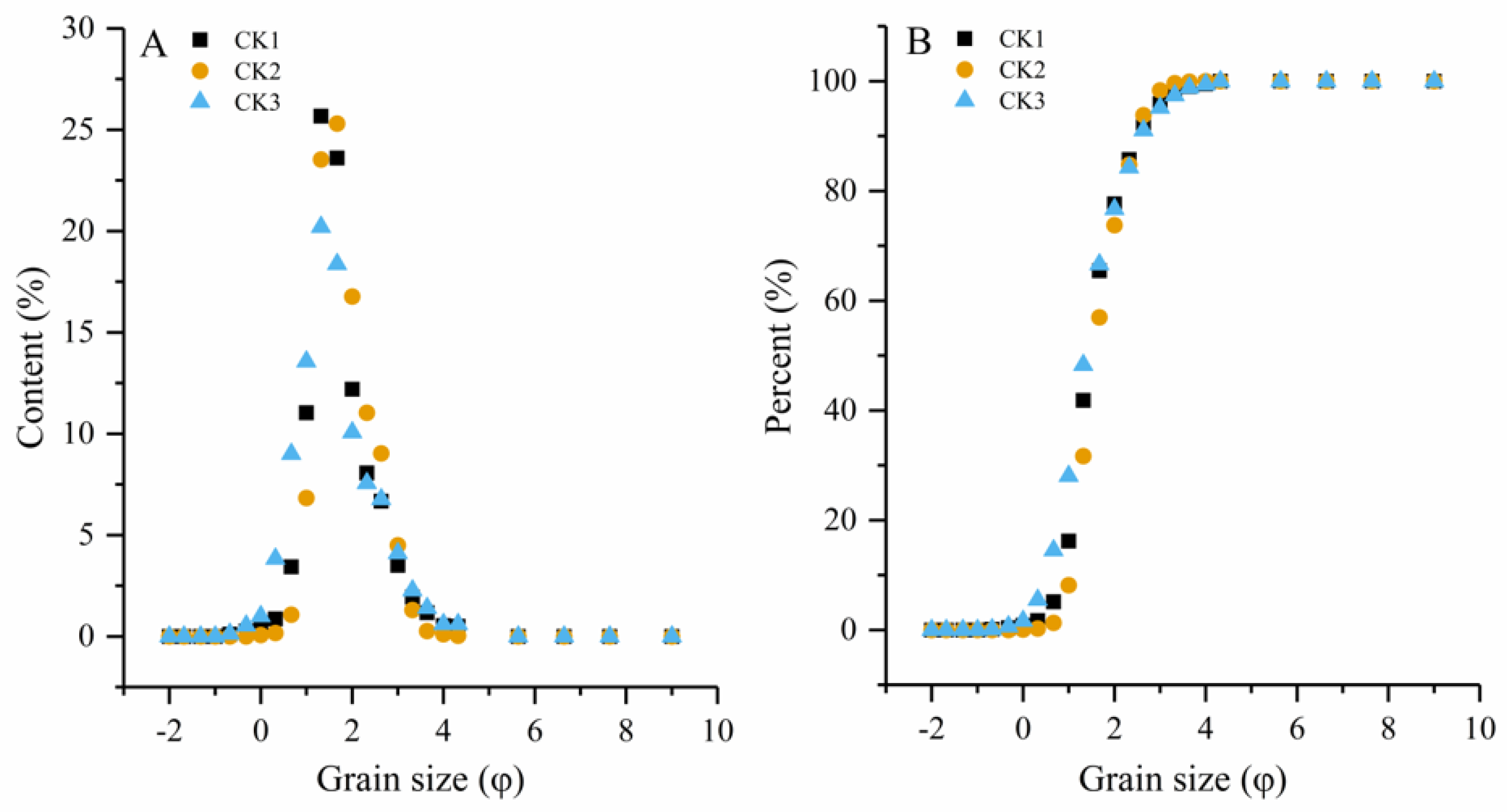
Field investigation of sand morphology and particle size
The typical barchan dune near the opencut tunnel was selected by the PENTAX R-300X total station to determine its morphological characteristics, and the sand samples were collected from different parts of the dune and brought back to the laboratory for analysis by a laser particle size analyzer.

3. Results

3.1. Characteristics of Wind and Sand without the Model

The wind and sand characteristics of the wind tunnel without the model are presented in this section. Figure 4A,C presents the characteristics of the wind speed profile and flow field of the opencut tunnel model under 6 m/s, 8 m/s, 10 m/s and 12 m/s. Figure 4B shows the variation curve of sediment flux with height. As shown in the figure, wind speed and sediment flux conform to the law of variation of aeolian sand movement. The variation trend of different wind speeds is similar. Furthermore, the absence of the model in the wind tunnel does not affect the sand movement, indicating that the wind tunnel can be tested normally to a certain extent.

3.2. Characteristics of Airflow Velocity Field with the Opencut Tunnel

The characteristics of the airflow velocity field with the opencut tunnel when there is a model in the wind tunnel are shown in Figure 5. Figure 5A,B shows the characteristics of the wind speed flow field before (−3H) and after (3H) of the opencut tunnel model under the condition of a 12 m/s indicative wind speed. Figure 5C,D shows the characteristics of the wind speed flow field before (−3H) and after (3H) of opencut tunnel model under four indicative wind speed conditions when the wind direction angle is 90°.
In the case of an opencut tunnel, the wind speed at the front and rear of the model is consistent with the height change and increases with an increase in the height based on the logarithmic function law. Wind speed at the front (−3H) of the model has a logarithmic function in relation with height, and the wind speed gradually increases with an increase in the height. However, this change rule is not affected by the wind direction angle and indicated wind speed; it conforms to the change law of the wind speed profile. Under the influence of the opencut tunnel model and under different wind direction angles, the variation of wind speed with height after the model (3H) is relatively complex. The airflow velocity first decreases and then increases with the increase in vertical height. The variation of wind speed with height can be roughly divided into 0°–30°, 30°–75° and 75°–90°. The angle between the three types presented weak wind that appeared in a 1–20-cm layer near the surface, and when the height is >30 cm, the wind speed increases sharply. With the increase in the wind direction angle, the change rule is not affected by the indicated wind speed. The control effect on the near-surface wind speed is the strongest, which also indicates that the protection effect under this mode is better to a certain extent.

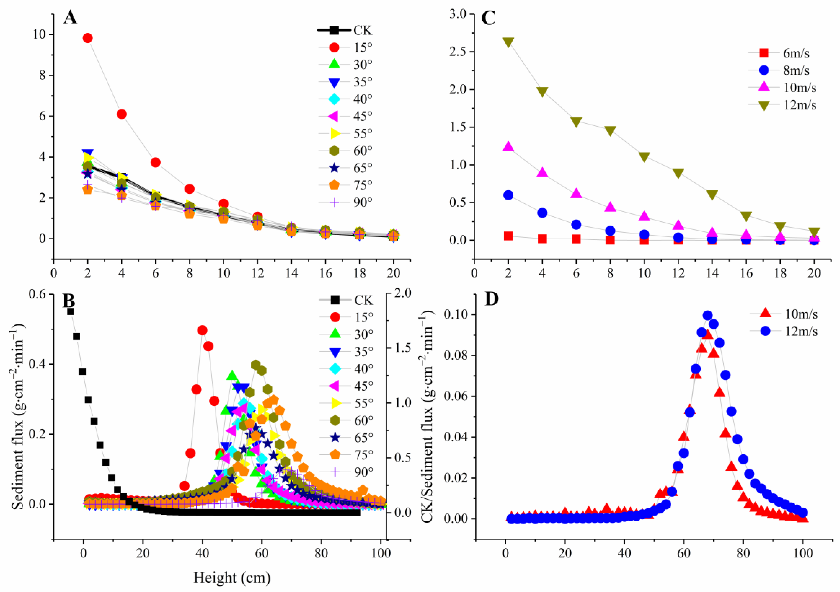
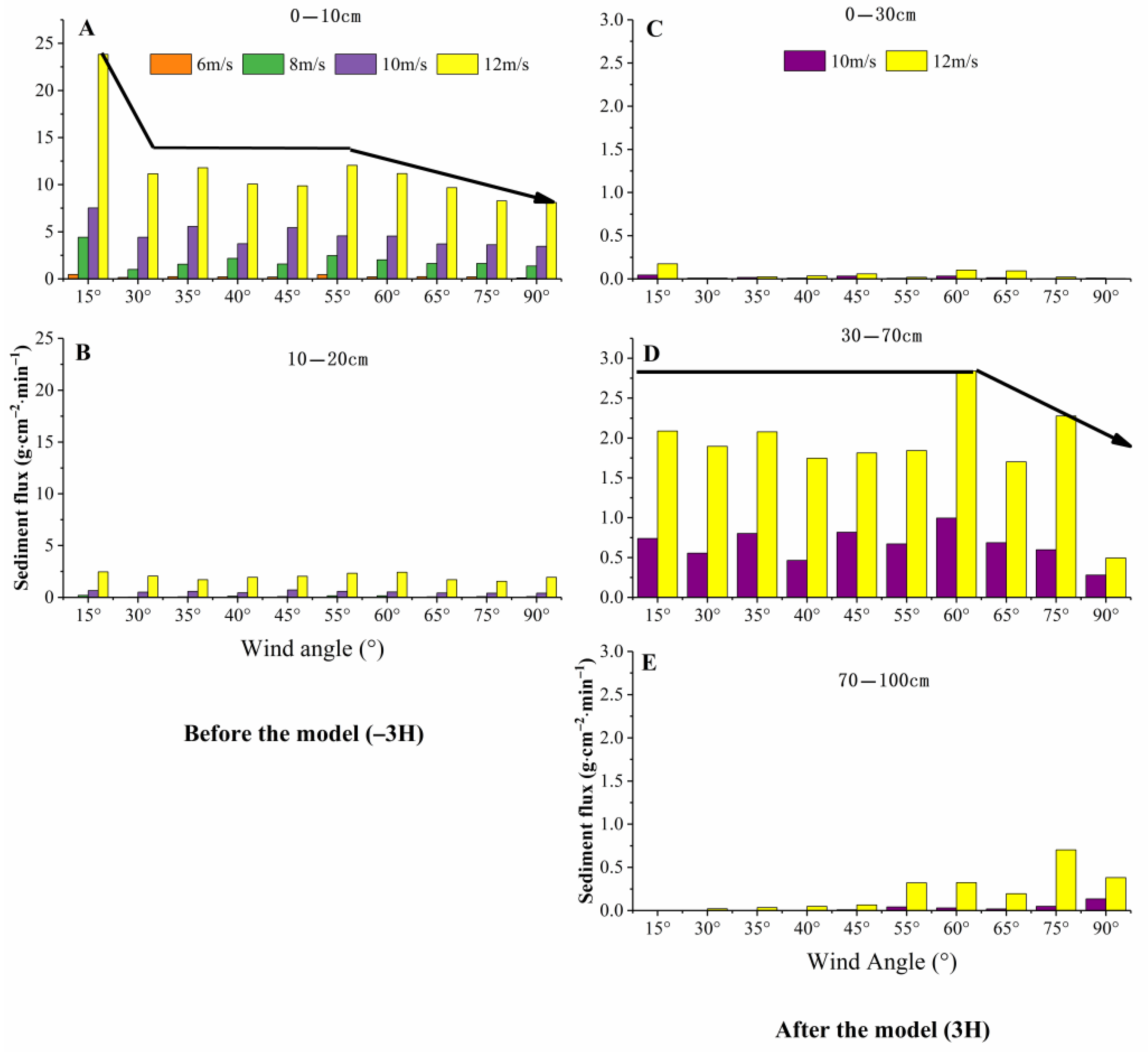
3.3. Vertical Distribution Characteristics of Wind–Sand Flow before and after the Opencut Tunnel

Under the four wind speeds of 6 m/s, 8 m/s, 10 m/s and 12 m/s, the vertical distribution characteristics of sand flow at the front and rear of the model at different wind directions are shown in Figure 6.
As can be seen in the figure, when the indicated wind speed is 12 m/s, the sand transport at the two typical positions in the cavity decreases continuously with the increase in height. The sediment transport in 0–10 cm height is 11.2989 g/cm2/min and 6.5853 g/cm2/min, respectively, 86.23% and 79.02% of the total sediment transport. The sediment transport in the range of 10–20 cm only accounts for 13.77% and 20.98% of the total. Furthermore, with the increasing indicated wind speed, the law that sediment transport decreases with the increase in height does not change.
As can be seen in Figure 6, the variation of near-surface sediment transport with height shows different laws under different wind speeds. In general, sediment transport decreases with height increase. With an increase in the angle between the wind speed and wind direction, the change of sediment transport on the windward side is small, and the sediment transport is mainly concentrated in the region of 0–10 cm height; the sediment transport rate is >85%. Owing to the influence of the model of the opencut tunnel, the distribution of aeolian sand flow at the 3-H leeward position no longer follows the law of aeolian sand flow. Instructions when the wind speed at a 90°–75° angle had an effect on preventing the opencut tunnel model because the wind direction angle changed little, and the leeward side sand flow structure was similar. Different heights of the sand flow structure change can be divided into three parts, including a 0–60 cm-high range, indicating that when the wind speed is 12 m/s, the sand flow slowly increases with increasing height; the average sediment transport of each layer is 0.0011 g/cm2/min, accounting for 9.80% of the total sediment transport. At a height of 60–70 cm, the sediment transport is greatly improved with increasing wind speed. At a wind speed of 12 m/s, the average sediment transport per layer is 0.0653 g/cm2/min, accounting for 46.41% of the total sediment transport. At a height of 70–100 cm, the sediment transport of the top layer decreases slowly and even drops to zero. At 12 m/s, the average sediment transport of each layer is 0.0255 g/cm2/min, accounting for 43.77% of the total sediment transport (Table 1).
Similarly, when the indicated wind speed acts on the opencut tunnel model at an angle of 65°–15°, the distribution of sediment transport at different heights is basically the same. The sediment transport increases slowly at 0–50 cm height, sharply increases at 50–65 cm height and slowly decreases at 65–100 cm height. Compared with the angle of 90° and 75°, in the height range of 0–100 cm, the peak value of sediment transport decreases from 70 cm to 40 cm. However, this process increases with the increase in the indicated wind speed, and its peak value moves forward and becomes smaller with the decrease in the action angle of the indicated wind speed. This may be because the direct force between the aeolian sand flow and the opencut tunnel decreases with the decrease in the angle of action, which leads to the gradual decrease of the intensity of the leeward aeolian sand flow and the gradual deposition of the aeolian sand flow (Figure 7).

3.4. Influence of Wind Direction on the Reattachment Distance of Airflow in the Opencut Tunnel

The model’s morphology and amount of sand accumulation were determined to reveal the blocking effect of different wind directions and wind speeds on the sand flow in the opencut tunnel. We used the surface area of sand to reflect the extent and amount of sand accumulation, which together reflect the capacity of sand accumulation. Under the condition of the same wind speed, with a decrease in the wind direction angle, the change of sand accumulation surface area around the model of the opencut tunnel shows a continuous increase process. As the wind direction angle decreases, the opencut tunnel model blocks the windward side. A large amount of sand accumulates along the edge of the model, increasing surface area.
By contrast, the leeward side accumulates relatively less sand, which has been fully proved by the wind tunnel experiment. Similarly, in the case of the same wind direction angle, with an increase in the wind speed, the sand shape (surface area) around the opencut tunnel generally increases continuously. However, with an increase in the wind direction angle, the ranges of sand deposition on the windward and leeward sides tend to be the same, while the surface area of sand deposition on the windward side is larger than that on the leeward side (sand superficial area and volume data are shown in Table 1).
Under the condition of different indicative wind speeds, the variation of sediment accumulation at the included angle of ten wind directions is different (Figure 8). When the indicated wind speed is 10 m/s and 12 m/s, the sediment accumulation around the opencut tunnel increases first and then decreases slowly with the decrease in the angle between wind direction. However, the sediment accumulation increases slowly during the whole process. When the indicating wind speed is 6 m/s and 8 m/s, this action process is not obvious. In the interval of [90°, 15°], sediment accumulation basically fluctuates up and down at the same level. This phenomenon may occur because the larger the airflow velocity, the greater the impact force between the sand flow and opencut tunnel model. Similarly, under the same wind direction angle, the sediment accumulation around the opencut tunnel considerably improves with increasing wind speed.

4. Discussion

4.1. The Relationship between Wind Direction Angle and Airflow Velocity Field and Sand Transport

The completion of an opencut tunnel transforms the original “primary” airflow through the surface into a special form of “secondary” airflow, considerably changing the airflow speed and direction of the airflow near the opencut tunnel. These changes affect the deposition and migration of aeolian sand flow around the opencut tunnel [36,37]. An opencut tunnel is a manmade obstacle on the surface, and the dynamic process of its sand-prevention system is controlled by the complex interaction between the opencut tunnel body, topography, wind direction, airflow and sand accumulation process [29]. Research results show that the airflow around an obstacle on the windward side is prone to separation due to the barrier blocking effect, forming part of the uplift and accelerated air over obstacles; the leeward side is affected by the pressure differential. The major factors controlling airflow are the weight-attached form of air flow, airflow and obstacles, etc. When the airflow acts on the open hole, the windward airflow is divided into a lower decelerating airflow, a middle uplifting accelerating airflow, and an upper turbulence, forming the weak wind region. The boundary layer is separated when the airflow crosses the opencut tunnel. Part of the airflow continues to be uplifted and accelerated, forming a strong wind zone at the top of the cavern, while the other part of the airflow decelerates or generates a reverse flow at the leeward side, forming a weak wind zone or a quiet wind zone.
The law of sediment transport is affected by the flow velocity field, and the sediment transport increases with the increasing height on the windward side; the difference between wind directions is insignificant. However, under the influence of the model, the distribution of the aeolian sand flow structure at the leeward position of 3 H no longer follows the law of the aeolian sand flow structure and 80% of the sediment transport is concentrated within the height range of 30–70 cm. The influence of the wind direction angle on the change in windward sediment transport can be roughly divided into four cases: the change at 90°–60° is the same, the change at 55°–30° tends to be the same, and the maximum sediment transport occurs at 15°. At the same wind speed, with a decrease in the wind direction angle, the changes in the sand surface area and sediment amount around the opencut tunnel model continuously increase. Wind field characteristics and an effective protection range determine that the construction of the tunnel can isolate the railway interior from the multi-direction wind and multi-sand environment, and the airflow characteristics of the tunnel at different wind direction angles determine the change law of sand transport. Results show that the opencut tunnel will not be buried under sand and the protection range at the angle range of 75°–90° is the best. However, different angles can effectively prevent sand flow disasters and ensure smooth railway operation.

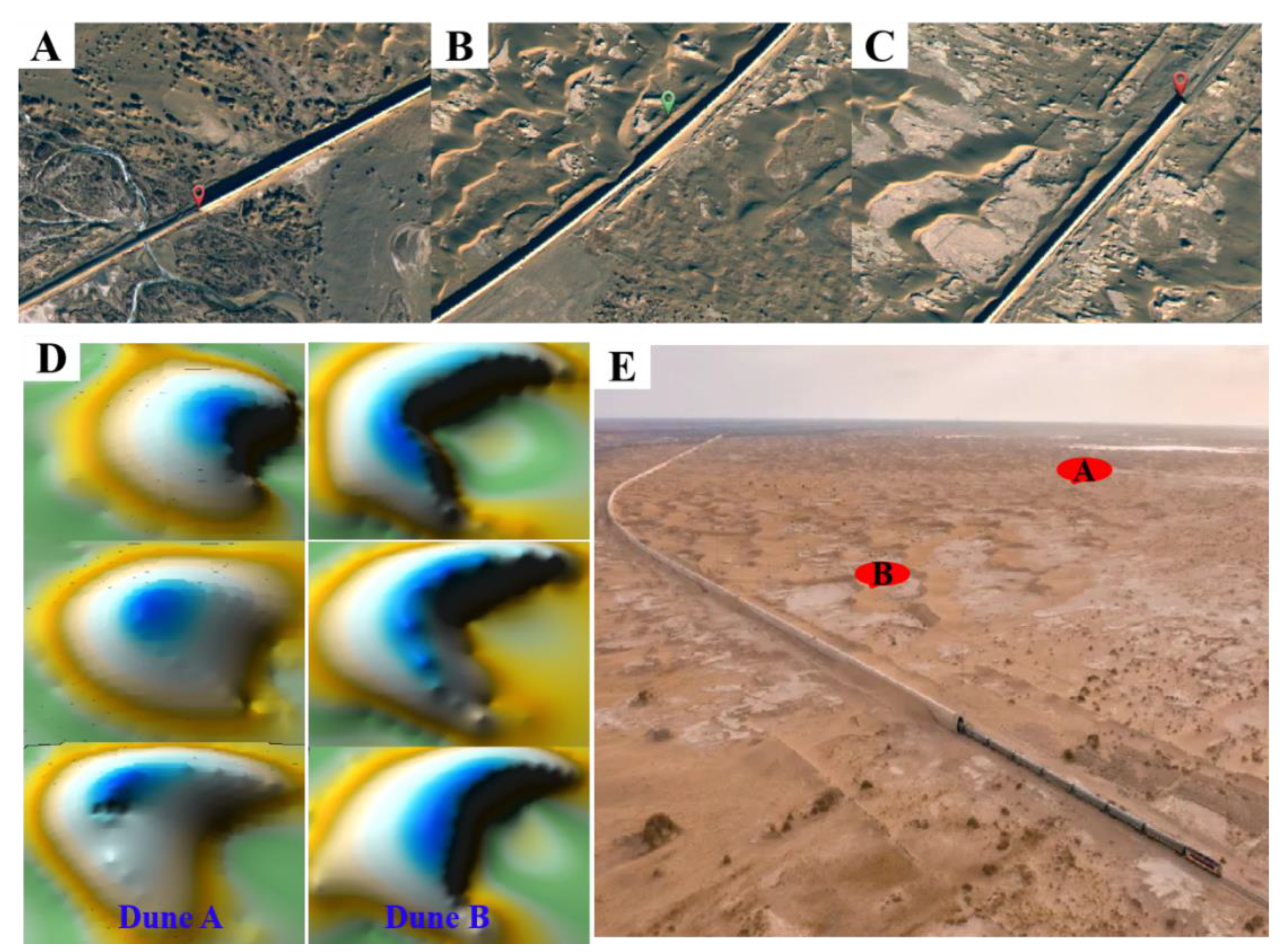
4.2. Field Demonstration of the Wind–Sand Environment in the Opencut Tunnel

The wind–sand movement and the evolution of the wind–sand geomorphology in the windward side of the wind–sand tunnel are affected by the presence of a tall obstacle in the path of wind–sand movement. Therefore, the relation between an opencut tunnel and windblown sand environments is mutual and reciprocal. There are many studies regarding the influence of obstacles on aeolian sand movement and the evolution of aeolian geomorphology [38,39]. All kinds of engineering and plant measures for sand control and prevention can be regarded as obstacles to aeolian sand movement. However, the research and practice of the traditional small size of the obstacles, its influence on sand movement and sand landforms evolution laws may also not be able to explain the influence of the big size of obstacles; the large-size opencut tunnel on sand movement and the size of the influence of the degree of sand landform evolution have not yet been reported.
Therefore, an empirical field study regarding the influence of opencut tunnels on aeolian sand movement and geomorphology evolution was conducted herein. The aeolian geomorphology of the northwest edge of the Badain Jaran Desert, where the opencut tunnel of the Lin–Ce railway is located, mainly includes barchan dune, barchan dune chains, ancient clay riverbeds and rugid Yadan. Barchan dune is preferred for quantitative study. Since the main wind directions in the study area are western and northwestern, the independent barchan dune located at the north of the opencut tunnel 500 meters away from the opencut tunnel was selected as the typical dune Awith regard to sand particle size and dune movement in the study area. An independent barchan dune was selected as the dune B disturbed by the north side of the opencut tunnel within 20 m. In the field investigation, the wind speed flow field and sand transport of the typical barchan dune were tested. The sand material of a typical dune at the end of the observation period was selected as the research object from the microscopic point of view to analyze the influence of an opencut tunnel on the change in the grain size characteristics. From a macroscopic point of view, typical dunes were selected as the research objects and the dynamic variation characteristics of dune movement parameters were analyzed in different observation periods, to reveal the rule of the resultant influence of opencut tunnels on aeolian sand movement and geomorphology evolution. The results show that the natural wind field structure of the barchan dune in the affected area was changed by an opencut tunnel. The surface sand was characterized by coarse-grained particles, improved particle size uniformity and concentrated particle size distribution. Moreover, the existence of an opencut tunnel made the morphological changes of the dune deviate from the normal development under natural conditions.

4.3. Analysis on the Possibility of Sand Burial in the Opencut Tunnel

For the design and construction process of the Lin–Ce railway opencut tunnel, considering the difficult situation of sand movement intensity at the Badain Jaran Desert edge, designers and railway maintenance departments were worried about the completion of the open tunnel because it may be buried in sand; the ventilation at the top of the opencut tunnel would not be buried. This study combines the wind tunnel test results and field investigation results to analyze and resolve these two problems.
According to the wind resistance of the opencut tunnel in the wind tunnel simulation results, the windward side at 6 H was a weak wind area; therefore, the area between the interval should be a quicksand accumulation zone. However, different change laws for gradient air velocity profiles also show that, due to the fact that the opencut tunnel itself does not leak, the lower the cause of the lower air velocity, the more the lower airflow direction changes. This shows that there is a reverse flow of lower flow in a certain range near the opencut tunnel. This phenomenon shows that even if there is a weak wind near the opencut tunnel, the accumulation of shifting sand is not close to the opencut tunnel, but is a certain distance from it. According to the wind direction in the area where the opencut tunnel is located, the included angle between the main harmful wind and the opencut tunnel is less than 70°. In this case, the lateral accelerated airflow forms in a certain range in the north of the opencut tunnel, taking away the quicksand accumulated under other wind directions, and having a natural sand-clearing effect. The average height of dunes near the opencut tunnel is no higher than that of the opencut tunnel. In terms of the evolution of aeolian geomorphology, the overall geomorphological change of the desert should be similar to that of the surrounding geomorphology on a centennial scale. Even if the aeolian sand is formed near the opencut tunnel, the height of the aeolian sand body is not higher than that of the surrounding dunes.
At present, it has been nearly 20 years since the construction of the opencut tunnel. We extracted images (Figure 9A–C) for interpretation and found no significant difference between the aeolian geomorphology along the opencut tunnel and its surrounding areas. The figure shows that the barchan dune chain spreading to the northeast and southwest intersects with the opencut tunnel. Although there is some quicksand accumulation in the north of the opencut tunnel, the accumulation amount is not large, and there is a certain distance from the opencut tunnel. At the same time, it can be seen that the amount of shifting sand in the south of the opencut tunnel is less, and the distance from the opencut tunnel is larger. It was also found that the tunnel had been operating for 20 years without being buried by sand.
Based on the abovementioned situation, the open tunnel is not likely to be buried based on the theoretical results of the wind tunnel experiment or the field investigation.

4.4. Limitations of This Research

As with the majority of studies, the design of the current study is subject to limitations. It should be noted that our study has several limitations. For one, the data time series is short; the changes in sediment accumulation from year to year were not sharp. However, from the point of view of the law of sand movement, we showed that the opencut tunnel could not be buried, and we also found the images of the scene, which also proved that it will not buried. For another, all wind speeds and directions may not undergo the same wind tunnel tests. Therefore, there are still some limitations in the mechanism research; in the next step, we will do more in-depth research to provide more theoretical and data support for the popularization and use of the opencut tunnel.

5. Conclusions

(1)
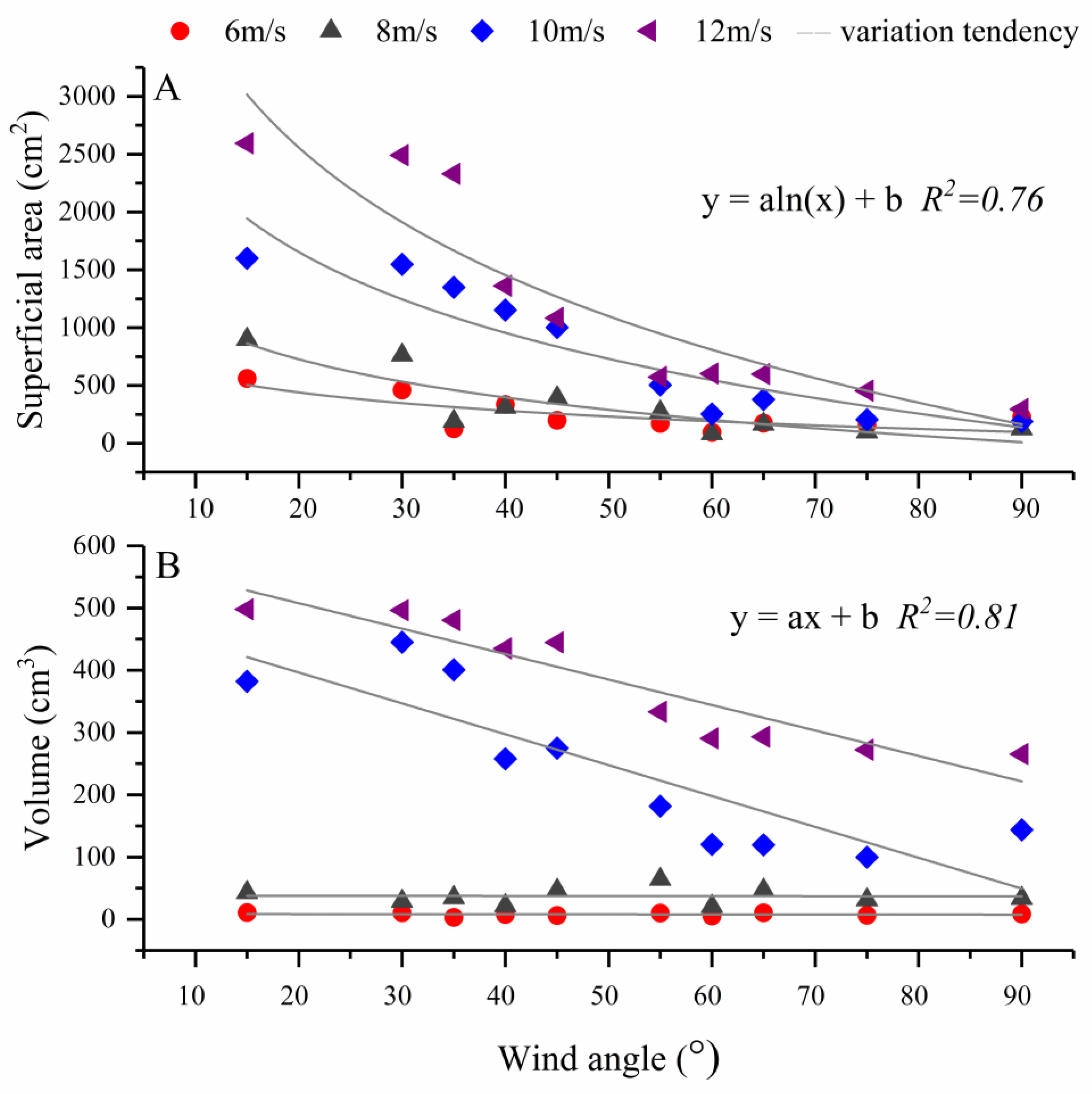
The sediment transport on the windward and leeward sides increased with increasing wind speed. More than 85% of the sediment transport on the windward side occurred within a height of 0–10 cm, while 80% of the sediment transport on the leeward side occurred within the height of 30–70 cm. The influence of the wind direction angle on the change in windward sediment transport can be roughly divided into four cases: the change process of 90°–60° is the same, the change of 55°–30° tends to be the same, and the maximum sediment transport can be observed at 15°. When considering the same indicated wind speed, with the decreasing wind direction angle, the change in the sand surface area and sediment amount around the opencut tunnel exhibits a continuous increase.
(2)
At the micro and macro scale, the grain size characteristics, morphology, movement direction and movement speed of the sand inside and outside the opencut tunnel area are influenced by the construction of the opencut tunnel. The sand particles on the dune surface in the opencut tunnel area are coarse-grained, uniformly sized and centralized. Outside the influence area of the opencut tunnel, the dune movement exhibits a small deflection, the annual linear movement distance is more than 30 m, and the morphology of the dune gradually evolves into a typical barchan dune.
(3)
The greater the angle between the opencut tunnel and wind direction, the higher the wind and sand resistance potential. When constructing the sand-control opencut tunnel in similar desert areas, the opencut tunnel should intersect the dominant wind direction at as large an angle as possible. The variation law of airflow velocity profiles under different wind levels and angles shows that the airflow above 0.7 times the height is in a state of acceleration and uplift and no sand-filling phenomenon occurs at the ventilation vent at the top of the open tunnel. In the past 20 years, no accumulation of shifting sand occurred along the opencut tunnel. Affected by the main adverse wind and the acceleration of gathering wind in the opencut tunnel, there was always a certain distance from the sand body along the line to the opencut tunnel and the shifting sand could not bury the opencut tunnel in a small-scale time range. Therefore, an opencut tunnel can be used for railway prevention.

Author Contributions

M.Y. wrote the main manuscript text and prepared the Figures. In addition, M.Y. and H.Z. reviewed and revised the manuscript. M.Y. and H.Z. contributed equally to the manuscript text. All authors have read and agreed to the published version of the manuscript.

Funding

This research was supported by the Talent program of the Inner Mongolia Agricultural University (NDYB2020-7) and Inner Mongolia Natural Science Foundation project (No. 2021BS03039).

Institutional Review Board Statement

Not applicable.

Informed Consent Statement

Not applicable.

Data Availability Statement

The data presented in this study are available on request from the corresponding author.

Acknowledgments

The authors would like to thank the Talent program of the Inner Mongolia Agricultural University and Inner Mongolia Natural Science Foundation project. In addition, the authors are grateful to the editor and the anonymous reviewers for their comments.

Conflicts of Interest

The authors declare no conflict of interest.

References

  1. Yan, M.; Wang, H.B.; Zuo, H.J.; Li, G.T. Wind tunnel simulation of an opencut tunnel airflow field along the Linhe-Ceke Railway, China. Aeolian Res. 2019, 39, 66–76. [Google Scholar] [CrossRef]
  2. Xu, X.; Zhang, K.; Kong, Y.; Chen, J.; Yu, B. Effectiveness of erosion control measures along the Qinghai–Tibet highway, Tibetan plateau, China. Transp. Res. Part. D Transp. Environ. 2006, 11, 302–309. [Google Scholar] [CrossRef]
  3. Cheng, J.; Jiang, F.; Xue, C.; Xin, G.; Li, K.; Yang, Y. Characteristics of the disastrous wind-sand environment along railways in the Gobi area of Xinjiang, China. Atmos. Environ. 2015, 102, 344–354. [Google Scholar] [CrossRef]
  4. Xiao, J.H.; Yao, Z.Y.; Qu, J.J. Influence of Golmud-Lhasa section of Qinghai-Tibet Railway on blown sand transport. Chin. Geogr. Sci. 2015, 25, 39–50. [Google Scholar] [CrossRef]
  5. Zhang, K.C.; Qu, J.J.; Yu, Y.P.; Han, Q.J.; Wang, T.; An, Z.S.; Hu, F. Progress of Research on Wind-blown Sand Prevention and Control of Railways in China. Adv. Earth Sci. 2019, 34, 573–583. [Google Scholar] [CrossRef]
  6. Mohebbi, M.; Rezvani, M.A. Analysis of the effects of lateral wind on a high speed train on a double routed railway track with porous shelters. J. Wind. Eng. Ind. Aerodyn. 2019, 184, 116–127. [Google Scholar] [CrossRef]
  7. Song, Y.; Zhang, M.; Iseth, O.; Ronnquist, A. Wind deflection analysis of railway catenary under crosswind based on nonlinear finite element model and wind tunnel test. Mech. Mach. Theory 2022, 168, 104608. [Google Scholar] [CrossRef]
  8. Zhang, K.; Qu, J.; Han, Q.; Xie, S.; Kai, K.; Niu, Q.; An, Z. Wind tunnel simulation of windblown sand along China’s Qinghai–Tibet railway. Land Degrad. Dev. 2012, 25, 244–250. [Google Scholar] [CrossRef]
  9. Woldman, M.; Van, H.E.; Schipper, D.J.; Tinga, T.; Masen, M.A. Investigating the influence of sand particle properties on abrasive wear behaviour. Wear 2012, 294, 419–426. [Google Scholar] [CrossRef]
  10. Kóllmann, J. Railway operations under harsh environmental conditions sand, dust & humidity problems and technical solutions/mitigation measures. In Proceedings of the AHK Workshop Be a Partner of Qatar Rail, Berlin, Germany, 17 April 2013. [Google Scholar]
  11. Tyfour, W.R. Predicting the effect of grinding corrugated rail surface on the wear behavior of pearlitic rail steel. Tribol. Lett. 2008, 29, 229–234. [Google Scholar] [CrossRef]
  12. Thake, T. ERTMS Implementation in Saudi Arabia; International Strategic Rail Forum: Abu Dhabi, United Arab Emirates, 2012. [Google Scholar]
  13. Selig, E.T.; Waters, J.M. Track Geotechnology and Substructure Management; Thomas Telford Services Ltd.: London, UK, 1994. [Google Scholar]
  14. Esmaeili, M.; Aela, P.; Hosseini, A. Experimental assessment of cyclic behavior of sand-fouled ballast mixed with tire derived aggregates. Soil Dyn. Earthq. Eng. 2017, 98, 1–11. [Google Scholar] [CrossRef]
  15. Wang, X.; Zhang, D.; Jiang, Y.; Jiang, F.; Li, Y. Drifting sand disasters and engineering control along south Xinjiang railway line. Chin. J. Geol Hazard. Control. 2007, 18, 59–63. [Google Scholar] [CrossRef]
  16. Zhang, K.C.; Qu, J.J.; Liao, K.T.; Niu, Q.H.; Han, Q.J. Damage by wind-blown sand and its control along Qinghai-Tibet Railway in China. Aeolian Res. 2010, 1, 143–146. [Google Scholar] [CrossRef]
  17. Zhang, K.; Qu, J.; Han, Q.; An, Z. Wind energy environments and aeolian sand characteristics along the Qinghai–Tibet Railway, China. Sediment. Geol. 2012, 273, 91–96. [Google Scholar] [CrossRef]
  18. Cheng, J.; Xue, C. The sand-damage–prevention engineering system for the railway in the desert region of the Qinghai-Tibet plateau. J. Wind. Eng. Ind. Aerodyn. 2014, 125, 30–37. [Google Scholar] [CrossRef]
  19. Hotta, S.; Horikawa, K. Function of sand fence placed in front of embankment. Coast. Eng. 1991, 2754–2767. [Google Scholar] [CrossRef]
  20. Dong, Z.; Li, H.; Wang, J.; Ding, G.; Sun, B. Wind tunnel test on effect of controlling windand deposited sand of geogrid sand-barrier. Sci. Soil Water Conserv. 2007, 5, 35–39. [Google Scholar] [CrossRef]
  21. Huang, N.; Xia, X.; Tong, D. Numerical simulation of wind sand movement in straw checkerboard barriers. Eur. Phys. J. E Soft Matter 2013, 36, 1–7. [Google Scholar] [CrossRef]
  22. Xu, Y.; Mustafa, M.Y. Using CFD based virtual sensor data to study the structure of air flow behind a porous fence. In Proceedings of the 8th International Conference on Sensor Technologies and Applications (SENSORCOMM’14), Lisbon, Portugal, 16–20 November 2014; pp. 39–44. [Google Scholar]
  23. Xu, B.; Zhang, J.; Huang, N.; Gong, K.; Liu, Y. Characteristics of turbulent aeolian sand movement over straw checkerboard arriers and formation mechanisms of their internal erosion form. J. Geophys. Res. Atmos. 2018, 123, 6907–6919. [Google Scholar] [CrossRef]
  24. Cheng, J.; Lei, J.; Li, S.; Wang, H. Disturbance of the inclined inserting-type sand fence to wind–sand flow fields and its sand control characteristics. Aeolian Res. 2016, 21, 139–150. [Google Scholar] [CrossRef]
  25. Wang, T.; Qu, J.; Ling, Y.; Xie, S.; Xiao, J. Wind tunnel test on the effect of metal net fences on sand flux in a Gobi Desert, China. J. Arid. Land 2017, 9, 888–899. [Google Scholar] [CrossRef]
  26. Bruno, L.; Horvat, M.; Raffaele, L. Windblown sand along railway infrastructures: A review of challenges and mitigation measures. J. Wind. Eng. Ind. Aerodyn. 2018, 177, 340–365. [Google Scholar] [CrossRef]
  27. Lynch, K.; Jackson, D.W.; Cooper, J.A.G. Coastal foredune topography as a control on secondary airflow regimes under offshore winds. Earth Surf. Processes Landf. J. Br. Geomorphol. Res. Group 2010, 35, 344–353. [Google Scholar] [CrossRef]
  28. Bauer, B.O.; Davidson-Arnott, R.G.; Walker, I.J.; Hesp, P.A.; Ollerhead, J. Wind direction and complex sediment transport response across a beach–dune system. Earth Surf. Processes Landf. 2012, 37, 1661–1677. [Google Scholar] [CrossRef]
  29. Dong, Z.B.; Lv, P.; Zhang, Z.C.; Lu, J.F. Aeolian transport over a developing transverse dune. J. Arid. Land 2014, 6, 243–254. [Google Scholar] [CrossRef]
  30. Wiggs, G.F. Desert dune dynamics and the evaluation of shear velocity: An integrated approach. Geol. Soc. Lond. Spec. Publ. 1993, 72, 37–46. [Google Scholar] [CrossRef]
  31. Lancaster, N.; Nickling, W.; Neuman, C.M.; Wyatt, V. Sediment flux and airflow on the stoss slope of a barchan dune. Geomorphology 1996, 17, 55–62. [Google Scholar] [CrossRef]
  32. Sauermann, G.; Andrade, J., Jr.; Maia, L.; Costa, U.; Araújo, A.; Herrmann, H. Wind velocity and sand transport on a barchan dune. Geomorphology 2003, 54, 245–255. [Google Scholar] [CrossRef]
  33. Zhang, C.; Li, Q.; Zhou, N.; Zhang, J.; Kang, L.; Shen, Y.; Jia, W. Field observations of wind profiles and sand fluxes above the windward slope of a sand dune before and after the establishment of semi-buried straw checkerboard barriers. Aeolian Res. 2016, 20, 59–70. [Google Scholar] [CrossRef]
  34. Zhang, Z.; Dong, Z.; Wu, G. Field observations of sand transport over the crest of a transverse dune in northwestern China Tengger Desert. Soil Tillage Res. 2017, 166, 67–75. [Google Scholar] [CrossRef]
  35. Bagnold, R.A. The Physics of Blown Sand and Desert Dunes; Methuen: New York, NY, USA, 1941. [Google Scholar]
  36. Mulhearn, P.; Bradly, E.F. Secondary flow in the lee of porousshelt erbelts. Bound. Layer Meteorol. 1997, 12, 75–92. [Google Scholar] [CrossRef]
  37. Liu, X.; Dong, Z. Experimental investigation of the concentration profile of a blowing sand cloud. Geomorphology 2004, 60, 371–381. [Google Scholar] [CrossRef]
  38. Bass, A.C.W. Complex systems in aeolian geomorphology. Geomorphology 2007, 91, 311–331. [Google Scholar] [CrossRef]
  39. Li, B.L.; Sherman, D.J. Aerodynamics and morphodynamics of sand fences: A review. Aeolian Res. 2015, 17, 33–48. [Google Scholar] [CrossRef]
Figure 1. Location of Linhe–Ceke railway.
Sustainability 14 11684 g001
Figure 2. Experimental models in the wind tunnel observation method (A) physical object of the opencut tunnel; (B,C) wind tunnel and test instrument; (D,E) sand accumulation on the windward and leeward sides of the model; (F) observation point of sediment morphology; (G) observation point of wind speed and wind–sand flow).
Sustainability 14 11684 g002
Figure 3. Particle size distribution characteristics (A) grain size frequency curve; (B) particle size cumulative frequency curve.
Sustainability 14 11684 g003
Figure 4. Wind and sand characteristics of the wind tunnel (without model: CK) (A) wind speed profile; (B) structure of wind–sand flow; (C) airflow velocity.
Sustainability 14 11684 g004
Figure 5. Characteristics of the airflow velocity field in the opencut tunnel. (A) at the windward side of the model with different angles under 12 m/s; (B) at the leeward side of the model with different angles under 12 m/s; (C) at the windward side of the model with different wind speeds under 90°; (D) at the leeward side of the model with different wind speeds under 90°.
Sustainability 14 11684 g005
Figure 6. Characteristics of the vertical distribution of wind–sand flow on the opencut tunnel. (A) at the windward side of the model with different angles under 12 m/s; (B) at the leeward side of the model with different angles under 12 m/s; (C) at the windward side of the model with a wind direction angle of 90°; (D) at the leeward side of the model with a wind direction angle of 90°.
Sustainability 14 11684 g006
Figure 7. Relation between the wind direction angle and sediment transport characteristics of the opencut tunnel. (A,B) characteristics of sediment transport at all the levels without the wind direction angle at the windward side of the model; (CE) characteristics of sediment transport at all the levels without the wind direction angle at the leeward side of the model.
Sustainability 14 11684 g007
Figure 8. Relation between the wind direction angle and sand surface area and quantity on the opencut tunnel.
Sustainability 14 11684 g008
Figure 9. Field demonstration of the wind–sand environment on the opencut tunnel (A) beginning section of the opencut tunnel, (B) middle section of the opencut tunnel, (C) end section of the opencut tunnel, (D) field dune morphology map and (E) photograph of the scene.
Sustainability 14 11684 g009
Table 1. Sediment Transport Characteristics of the Opencut Tunnel at Different Angles.
Angle (°)Wind Speed
(m/s)
Sediment (g)Sediment Flux (g/cm2/min)Precent of Sediment FluxSuperficial Aera (cm2)Volume (cm3)
FrontRearFrontRearFrontRear
U10/UU20/UU10/U20U0–30/UU30–70/UU70–100/U
15°619.11-0.48 -0.99 0.01 91.31 ---561.9710.99
8147.69-4.62 -0.96 0.04 22.54 ---899.4143.18
10163.8215.688.19 0.780.92 0.08 11.51 0.06 0.94 0.00 1600.97382.12
12315.4827.1426.29 2.260.91 0.09 9.66 0.00 0.49 0.03 2592.47498.04
30°66.50-0.16 -0.98 0.02 50.97 ---460.8010.62
833.28-1.04 -0.96 0.04 22.16 ---764.1629.03
1098.3911.274.92 0.560.90 0.10 8.59 0.19 2.22 0.00 1548.77445.13
12158.5723.1113.21 1.930.84 0.16 5.45 0.01 0.96 0.17 2490.44496.46
35°69.93-0.25 -0.99 0.01 67.98 ---127.23.28
852.00-1.63 -0.96 0.04 25.44 ---190.5834.98
10122.9416.456.15 0.820.90 0.10 9.47 0.01 0.67 0.00 1349.22400.74
12162.0225.6413.50 2.140.87 0.13 6.89 0.03 0.78 0.02 2329.78480.48
40°69.00-0.22 -0.98 0.02 61.47 ---334.807.72
846.18-1.44 -0.95 0.05 17.50 ---313.0522.05
1083.419.524.17 0.480.89 0.11 8.38 0.01 2.39 0.03 1152.50257.77
12144.2021.9912.02 1.830.84 0.16 5.20 0.06 1.55 0.18 1361.22435.04
45°67.56-0.19 -0.99 0.01 102.53 ---200.006.34
853.55-1.67 -0.95 0.05 18.58 ---393.1246.51
10123.1517.146.16 0.860.88 0.12 7.65 0.02 0.94 0.00 1003.41275.15
12142.9623.2411.91 1.940.83 0.17 4.86 0.01 0.59 0.02 1084.76444.61
55°617.95-0.45 -0.99 0.01 88.74 ---171.9910.02
883.96-2.62 -0.94 0.06 16.02 ---273.5364.46
10102.9914.385.15 0.720.89 0.11 7.97 0.02 1.73 0.03 504.06181.97
12172.6926.1714.39 2.180.84 0.16 5.18 0.04 0.78 0.09 573.30333.42
60°68.53-0.21 -0.98 0.02 56.61 ---95.555.70
869.88-2.18 -0.93 0.07 13.30 ---85.1420.96
10101.5621.165.08 1.060.90 0.10 8.53 0.01 0.44 0.00 254.39120.40
12163.3139.2213.61 3.270.82 0.18 4.59 0.00 0.30 0.02 603.45290.43
65°69.78-0.24 -0.93 0.07 12.76 ---175.1210.68
853.93-1.69 -0.97 0.03 33.09 ---166.5247.23
1082.8014.344.14 0.720.89 0.11 8.50 0.03 1.46 0.04 380.24119.56
12136.5523.8811.38 1.990.85 0.15 5.69 0.01 1.14 0.35 599.27293.33
75°68.74-0.22 -0.98 0.02 52.94 ---158.406.56
854.56-1.71 -0.96 0.04 23.27 ---98.8031.67
1080.6613.014.03 0.650.90 0.10 8.98 0.05 1.25 0.01 206.7499.88
12118.0535.999.84 3.000.84 0.16 5.32 0.01 0.15 0.08 455.40272.27
90°64.02-0.10 -0.98 0.02 42.19 ---229.408.80
846.20-1.44 -0.95 0.05 19.88 ---126.7233.87
1077.388.493.87 0.420.89 0.11 8.38 0.08 2.56 0.09 189.80143.90
12120.6110.5610.05 0.880.81 0.19 4.19 0.00 0.56 0.43 296.01265.35
Note: “-” indicates no item.
Publisher’s Note: MDPI stays neutral with regard to jurisdictional claims in published maps and institutional affiliations.

