Article

Microgrid Protection Using Magneto-Resistive Sensors and Superimposed Reactive Energy

by
Musfira Mehmood
1,
Syed Basit Ali Bukhari
2,
Abdullah Altamimi
3,4,*,
Zafar A. Khan
5,
Syed Ali Abbas Kazmi
1,*,
Muhammad Yousif
1 and
Dong Ryeol Shin
6
1
US-Pakistan Center for Advanced Studies in Energy (USPCAS-E), National University of Sciences and Technology (NUST), H-12, Islamabad 44000, Pakistan
2
Department of Electrical Engineering, The University of Azad Jammu and Kashmir, Muzaffarabad 13100, Pakistan
3
Department of Electrical Engineering, College of Engineering, Majmaah University, Al-Majmaah 11952, Saudi Arabia
4
Engineering and Applied Science Research Center, Majmaah University, Al-Majmaah 11952, Saudi Arabia
5
Department of Electrical Engineering, Mirpur University of Science and Technology, Mirpur 10250, Pakistan
6
Department of Electrical and Computer Engineering, College of Information and Communication Engineering (CICE), Sungkyunkwan University (SKKU), Suwon 16419, Republic of Korea
*
Authors to whom correspondence should be addressed.
Sustainability 2023, 15(1), 599; https://doi.org/10.3390/su15010599
Submission received: 2 November 2022 / Revised: 29 November 2022 / Accepted: 2 December 2022 / Published: 29 December 2022
(This article belongs to the Section Energy Sustainability)

Abstract

:
The concept of microgrids has emerged as an effective way to integrate distributed energy resources (DERs) into distribution networks. The presence of DERs in microgrids leads to challenges in the formulation of protection for microgrids. Protection problems arise in a microgrid due to varying fault current levels in different operating scenarios. In order to overcome the practical challenges arising from varying fault current levels leading to short-circuit faults in microgrids, this paper proposes a MagnetoResistive (MR) sensors-based protection scheme, with fault localization through SuperimposedReactiveEnergy (SRE). The process is initiated by employing highly sensitive non-intrusive magnetic sensors to detect the magnetic field at each end of the distribution line. The magnetic field is then used to calculate the total harmonic distortion and thus detect faults in microgrids. After detection of faults, the proposed scheme uses SRE to identify faulty zones in microgrids. Finally, SI components of the current are extracted for fault classification. Extensive simulations on the International Electro-technical Commission (IEC) microgrid are performed in MATLAB/Simulink to validate the efficacy of the proposed scheme. Simulation results show that the proposed scheme can effectively detect, classify and isolate different faults in microgrids, while operating under various modes with varying fault locations and resistances, with the efficiency of approximately 97–98%.

1. Introduction

With the advancement in the energy sector, an efficient and robust power system is the need of the time and the progress of modern society. Recently, the depletion of traditional energy resources, the expansion in load demands and environmental concerns have encouraged the clean and environment-friendly methods for the generation of electricity. These energy resources are integrated into the power system at distribution end and termed as distributed energy resources (DERs) [1]. In contrast to conventional complex and unidirectional distribution networks, the integration of DERs has opened a new path for reliable, efficient, economical and smaller-scale distribution networks which are usually termed as microgrids [2,3]. Microgrids can flexibly work in parallel with the utility grid in grid-connected mode as well as without the utility grid in islanded mode of operation [4]. Although the microgrids’ operation is advantageous, it is accompanied with various control- and protection-related challenges [5]. The main issue related to microgrid protection arises during the islanded mode of operation when the microgrid operates independently in isolation from the main grid. In this case, fault currents generated by inverter-based DERs are small, merely 2–3 times the full-load current [6]. Thus, it confuses the traditional control and protection schemes which rely on the large fault currents and unidirectional power flows [7]. However, it is possible to use traditional over current protection relays in the grid-connected mode as the utility grid contributes to fault currents which result in higher fault current levels, i.e., 8–10 times the full-load current. The induction of DERs changes the direction and level of fault currents, hence disturbing the relay coordination.
A protection scheme for microgrids must guarantee smooth operation in grid-connected as well as in islanded mode [8] and should encounter (1) two-way power flow, (2) different level of fault currents during grid-connected and islanded mode of operation, and (3) formation of looped feeders. Several microgrid protection schemes have been suggested in the literature [9,10]. Central processing unit-based microgrid protection has been proposed in [11], in which pre- and post-positive sequence impedance of fault were computed and analyzed at both terminals of the line to estimate the fault point. However, up-gradation of currently used protection devices is required for its implementation. In [12], an S-transform is applied on the current signal at both ends for the calculation of differential energy to detect the faults in microgrids. Then, the maximum amplitude curve is used for the classification of faulty phases. In [13], mathematical morphology is applied to extract the travelling wave for the safety of microgrids. Very high sampling frequency and synchronization of signals are required for the application of this scheme, making it unserviceable due to the high cost of the DSP kit. In [14], switching of the converter from droop control to current control was suggested at the time of faults. Estimation of the fault point was achieved by checking the status of the converter. This scheme was tested for microgrids with inverter interface DERs only. In [15], microgrid protection is based on current magnitude, voltage sag and active power flow. However, the implemented scheme is tested only for inverter-based microgrids.
A differential protection scheme for inverter-based microgrids was suggested in [16], which depends on off-nominal frequencies injection by voltage frequency control. However, the proposed scheme is analyzed on inverter-based islanded microgrids only. An online method has been proposed in [17] to calculate and update the setting of adaptive over current relays during transition of the microgrid from grid-connected to islanded mode and vice versa. However, extensive and complex fault calculations were required when the microgrid changed its mode of operation. Installation of energy storage devices was proposed in [18] to balance the fault current level in both islanded and grid-connected mode, although integration of such devices with a high short-circuit capability is not feasible from an economical perspective. Authors in [19] used an SVM classifier for the detection of faults in microgrids. In addition, localization of faults is achieved by harmonic injection. However, this scheme is implemented on meshed microgrids. Superimposed sequence components-based differential protection was suggested in [20] for the protection of microgrids only in grid-connected mode. A wavelet packet transform-based scheme is presented in [21] to clear the fault using high frequency components of current and voltage. It also uses a high pass filter for WPT realization. However, it only considered radial configuration of microgrids. A low pass filter and square law method is used in [22] to obtain the current envelope for microgrid protection against solid faults. In [23], dynamic adaptive overcurrent relays were used for protection of faults in microgrids. This scheme is tested only for radial configuration of microgrids. Teager–Kaiser energy operator-based microgrid protection is presented in [24] for investigating the current waveform at one end of the considered line for identification and classification of faults.
The limitation to above-mentioned schemes is that they are applicable for one mode (grid-connected or islanded mode) or they take into account only the radial configuration of microgrids. This paper presents a simple, robust and efficient methodology for the protection of microgrids against faults during both grid-connected as well as islanded modes of operation. The proposed scheme uses a non-intrusive magnetic field measurement through MR sensors for the identification of faulty events in microgrids. The features that make MR sensors highly valuable are tiny size, sensitive nature of detection/sensing (5 mV/V/0.1 mG), which holds the capacity to replace current transformers [25], and the intrinsic property of high resistance thus consuming less power [26]. The quality of the sensing magnetic field with broad frequency bandwidth (DC to MHz) without any junction in the real network enhances its worth to be used for detecting minute changes. Recently, magnetic field waveforms have been taken into account for the sensing and localization of faults for overhead lines [27,28].
So, in this paper, a highly precise, economical approach is presented for the detection of transient current during short-circuit faults using non-intrusive MR sensors by a delay of just 10 nanoseconds. The scheme employs superimposed reactive energy (SRE) to classify and locate faults in microgrids. Exhaustive simulations are conducted on MATLAB/SIMULINK software to verify and test the proposed protection algorithm and the results verify its effectiveness. The main features of this paper are:
  • The presented scheme can non-intrusively sense the faulty conditions using MR sensors without any modification and disturbance to the current system.
  • The scheme works well with radial as well as looped micro-grids with different configurations against solid faults having the capability of single line tripping.
  • The proposed protection mechanism works well with both grid-tied and islanded modes without any changes in relay setting during the transition of operational modes.
The paper is structured as follows. Section 2 formulates the mathematical modeling for magnetic field calculations, superimposed components and SRE properties. The proposed protection scheme for the microgrid is explained in detail in Section 3. To validate the efficiency of the proposed protection scheme, simulation results are attached in Section 4. Section 5 concludes the research work that has been executed.

2. Mathematical Modeling of Proposed Protection Scheme

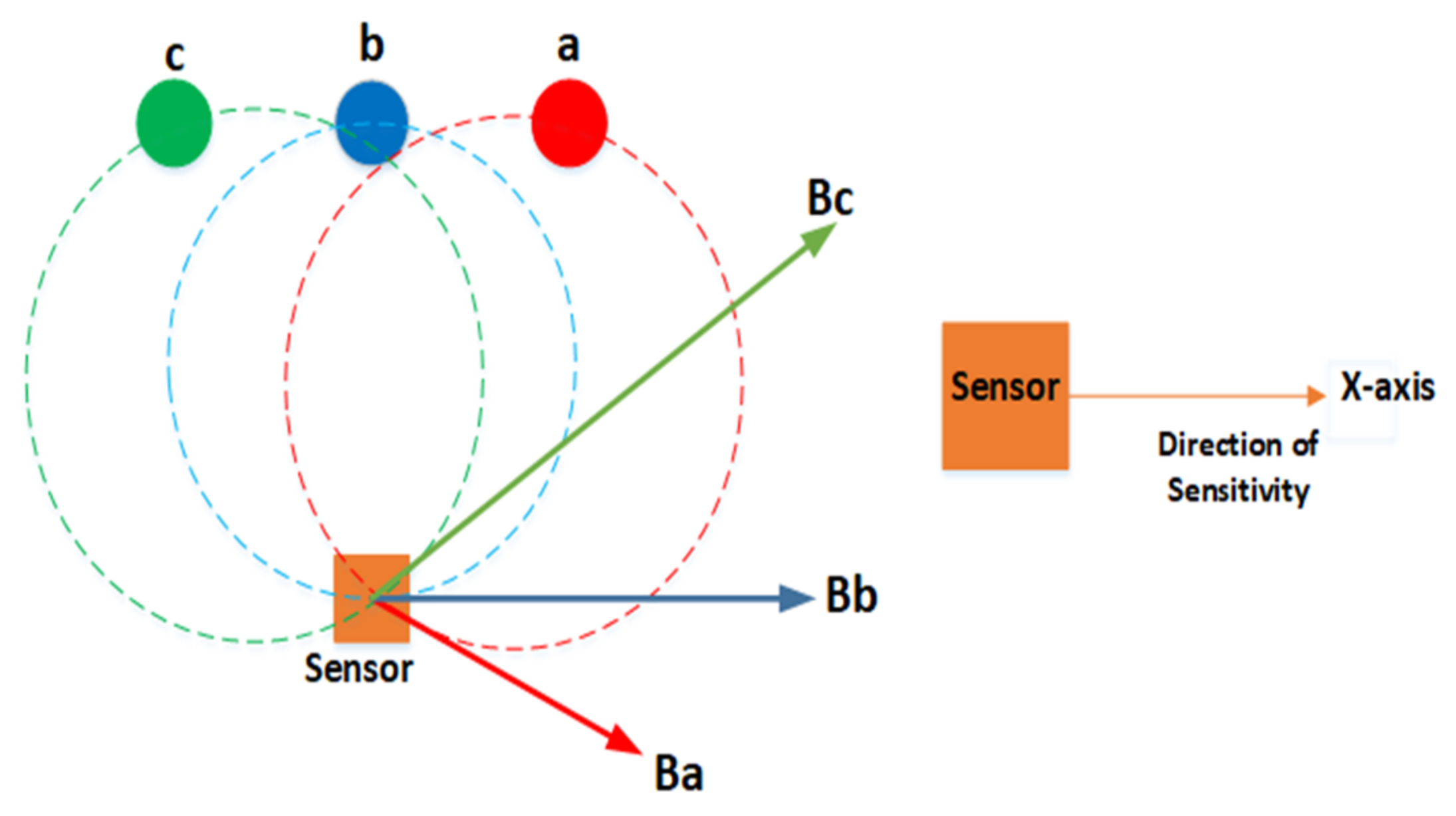
2.1. Magnetic Field Calculation

The magnetic field obtained at the sensor output depends on the placement of the sensor and the configuration of conductors. Thus, the magnetic field due to a single conductor is given by the Bio-Savart Law i.e.,
B = μ 0 I 2 π r
where “ μ 0 ” is air permeability, “ I ” is the flow of current in the conductors and “r” is the distance between the sensor and the source of current. Figure 1 shows different configurations of overhead distribution lines designed for the various pole layouts [28]. In the Figure 1, x 1 and x 2 are the horizontal distances from sensor to conductor whereas d is the distance from bottom-most conductor to ground. In this study, it is supposed that the sensor will be employed in the middle of the pole [28].
The magnetic field near the current-carrying source is in concentric circles and the direction of the magnetic field is tangent to the field lines. If the conductor sag is less as compared to the conductor span, then the effect of sag can be neglected in the calculations [29]. The position vectors r a , r b and r c and associated angles θ a and θ b are determined using trigonometric functions, as shown in Figure 2.
For the calculations, the magnetic field is resolved into its components B x and B y to compute its magnitude. For the three-phase circuit, the resulting magnetic field will be:
B = B x i x + B y i y + B z i z
B = B b + B a + B c c o s θ i x + B a B c s i n θ i y + 0 i z
B = μ 0 I b 2 π r b + μ 0 I a 2 π r a + μ 0 I c 2 π r c c o s θ i x + μ 0 I a 2 π r a μ 0 I c 2 π r c s i n θ i y + 0 i z
The direction of current is along the z-direction. The considered MR sensor is linear, so it will determine the magnetic field across its sensitivity direction, i.e., the horizontal direction shown in Figure 3 as given by:
B = μ 0 I b 2 π r b + μ 0 I a 2 π r a + μ 0 I c 2 π r c c o s θ i x
Considering the horizontal configuration of conductors in Figure 1, position vectors,   r a ,   r b   and   r c and angles, θ a   and   θ b as shown in Figure 3 can be expressed as:
r a = r c = x 2 + y 2 ,   r b = y
c o s θ a = c o s θ b = x x 2 + y 2
where x1 and x2 are equidistant for the horizontal configuration of conductors.
The magnetic field for all the possible layouts mentioned in Figure 1 of distribution lines will be:
B h o r i z o n t a l = μ 0 I b 2 π y 1 + μ 0 I a × x 1 2 π x 1 2 + y 1 2 + μ 0 I c × x 2 2 π x 2 2 + y 1 2 i x
B v e r t i c a l = [ μ 0 I b × x 1 2 π x 1 2 + y 2 2 + μ 0 I a × x 1 2 π x 1 2 + y 3 2 + μ 0 I c × x 1 2 π x 1 2 + y 1 2 i x
B t r i a n g u l a r = [ μ 0 I b × x 1 2 π x 1 2 + y 2 2 + μ 0 I a × x 2 2 π x 2 2 + y 3 2 + μ 0 I c × x 2 2 π x 2 2 + y 1 2 i x
The MR sensors-based detection method is advantageous due to its tiny size and highly sensitive nature of 5 mV/V/0.1 mG, which can detect even minute changes with a delay of just 10 nanoseconds with the topping of economical and non-intrusive specifications.

2.2. Superimposed Quantities (SIQ)

Whenever a fault occurs in microgrids, reasonable changes in electrical quantities such as current, voltage and power, etc. are observed. The rates of change in these quantities before and after faults are known as superimposed quantities. The superimposed quantities only appear when faults arise in an electrical network. One of the properties of superimposed components is that they exist only during faults. Thus, the quantities during faults at an instant can be represented as:
y f t = y t + y p f t
where y f t and y p f t are fault and pre-fault variables and y t denotes the change during the disturbance, which is called as a superimposed variable. It means the fault variable consists of pre-fault and superimposed components.
Equation (11) can be rearranged as:
y t = y f t y p f t
Equation (12) shows that a superimposed quantity can be computed by the subtraction of normal signature from its faulted signature. This can be achieved by implementing the delta filters [30]. In discrete form, the superimposed components can be represented as:
y k T = y k T s y k T s n T
where k is the number of samples, i.e., 1, 2, 3, 4, … , T s is sampling time period and n is the number of samples over one cycle. In other words, delta filters simply compute superimposed components by:
S I Q = S i g n a l D e l a y e d S i g n a l

2.3. Superimposed Reactive Energy (SRE)

In the proposed scheme, directional properties of superimposed reactive energy are used for the localization of faults. Superimposed current and voltage are used to compute reactive power using a Hilbert transform. In the Hilbert transform, the phase angle of signal is transformed by ±90°. The SRE at a fault point is given by:
E f = ± Z e q × V m 2 π ω
where Z e q represents equivalent impedance at the fault point. According to the fault point, change in impedance is described in [31] and the sign of SRE indicates whether the fault is a forward fault (FF) or a reverse fault (RF). If the relay measured the value of SRE as less than zero, it means that the fault is in a forward direction with respect to that relay. In the other case, if SRE is positive, it is an indication of the reverse fault as shown in Table 1.
The benefit of using SRE is that we can localize the fault section by dealing with the original sampled signal without interpreting and converting it to other forms and hence increasing the operational speed of the scheme.

3. Proposed Protection Scheme

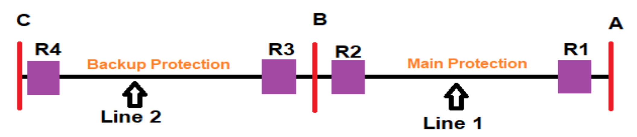
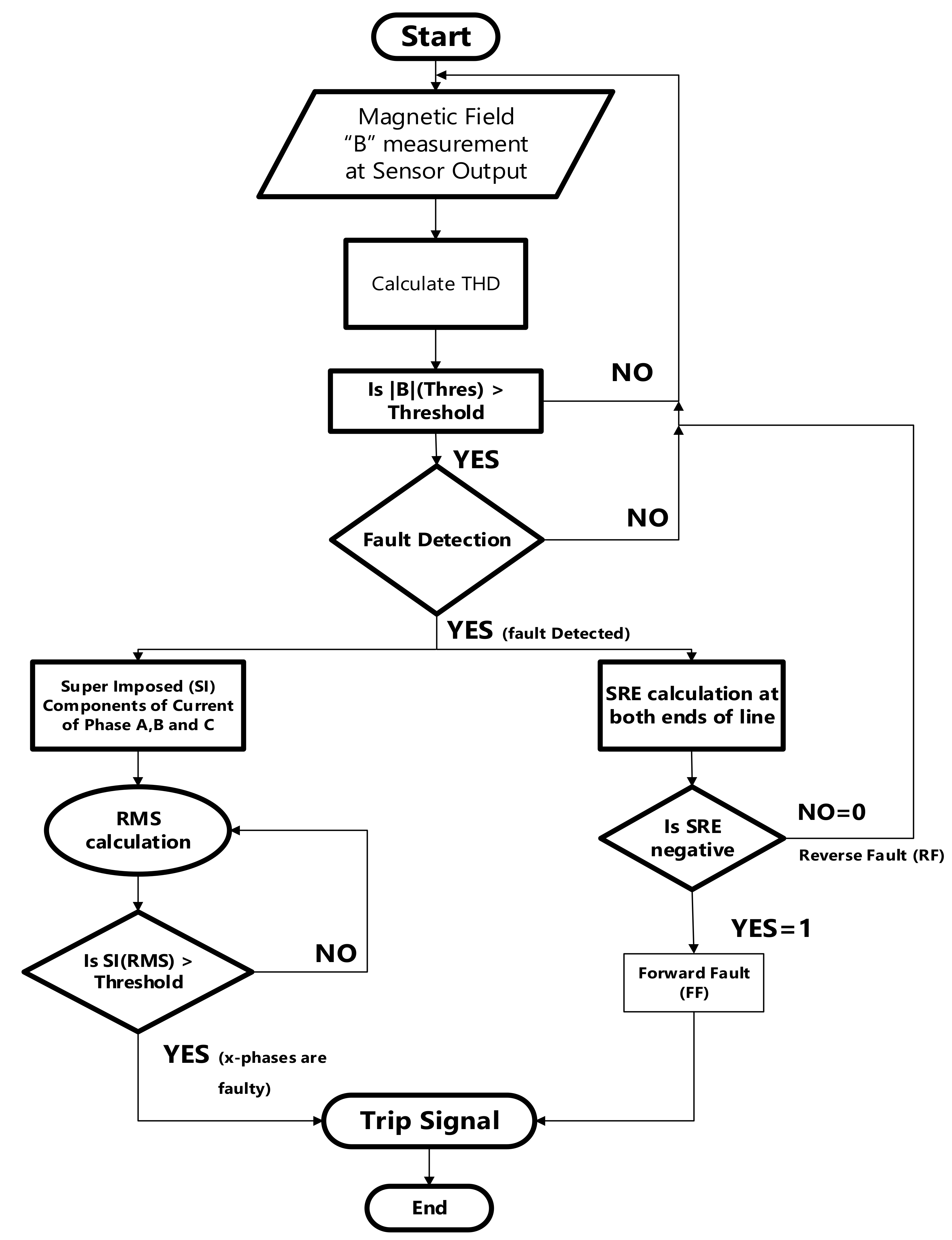
3.1. Fault Detection Scheme

In this paper, a new non-intrusive methodology for the fault detection in microgrids has been introduced based on the analysis of peak values of MF signals/waveforms. The main issue that arises for the protection of microgrids is the change (decrease) in the level of fault currents during the transition from grid-connected to islanded mode. As MR sensors are highly sensitive, so it has the capacity to observe minute changes and fluctuations. Therefore, it could be mounted near the feeder at a reasonable distance as shown in Figure 1. In this study, a horizontal configuration of towers is considered, having x = 1.197 m and y = 3 m. MR sensor output has two varying conditions/levels: (1) Normal; (2) Fault. Total harmonic distortion (THD) of magnetic field waveforms is calculated to detect the faults in microgrids. A threshold value is set to distinguish the faulty and non-faulty events in microgrids. Table 2 defines the value of the threshold during faulted grid-connected and islanded scenarios and looped configuration.

3.2. SRE-Based Protection Scheme

To localize the fault within the microgrid network, the SRE is used to locate the faulty region. Each relay in the proposed protection scheme is programmed with two operating modes: (1) main protection and (2) backup protection. In this study, data communication is established between three neighboring relays. Each relay sends two signals, i.e., fault detection B d e t and fault direction R d i r , to the other two relays. If the relays situated at both ends of Line 1 observe a fault to be a forward fault, then Zone 1(main protection) is considered as faulty and a trip signal will be generated; but if R1 detects a forward fault and R2 indicates a reverse fault, then a protection block will check the status of the fault at R4 by its received signal. If R4 identifies the fault to be a forward fault, then Zone 2 (backup protection) is considered as faulty and backup protection sends the trip signal after some pre-defined time delay. Ultimately, the trip signals from the main protection and backup protection are connected by OR logic to generate the FF trip signal. For the operation of the proposed protection technique, a communication- aided microprocessor-based protection relay is embedded on both ends of the line. As a fault can be forward or reverse for many relays, so to refrain from false tripping, a communication link is developed between three adjacent relays as shown in Figure 4. On the basis of received directional signals, R d i r from the relays’ faulty zone is indicated, which results in tripping of either main or backup protection. The flow chart of the presented scheme is given in Figure 5.

3.3. Proposed Protection Relay

The schematic diagram of the proposed protection scheme is shown in Figure 6. The proposed scheme consists of 4 main blocks: (1) Fault Detection; (2) Fault Directional and Localization; (3) Fault Classification; and (4) Tripping Block. Before feeding the signal to main units of the protection scheme, the input signals are pre-processed and passed through an ADC (Analog to Digital converter) having a 25 kHz sampling frequency. To ensure that the converted digital signal replicates and portrays the original signal, it is passed through a low pass filter to eliminate the aliasing.

3.3.1. Fault Detection Block

This block is modeled to identify the faulty events. The block uses a magnetic field waveform generated around the current-carrying conductors, which is measured by using highly sensitive MR (magneto-resistive) sensors. The sensors produce a fault detection B d e t signal for triggering of other blocks. This block tracks the changes in the THD of the magnetic field and compares it with the preset threshold value. As soon as the THD of the magnetic field crosses the threshold value, it generates the fault signal B d e t and enables the fault directional and localization block. The use of MR sensors not only helps to detect the solid faults but can also diagnose HIFs in both grid-connected and islanded modes.

3.3.2. Fault Directional and Localization Block

This block is used to identify the fault direction and to localize the faults. This block employs the SRE to identify the correct direction of faults in microgrid, once a faulty event is detected by the fault detection block. It generates an R d i r signal for further computation of faulty zones along with a B d e t signal. This block is in charge of triggering the main or backup protection relay after the occurrence of a fault. It identifies and localizes the zone of the fault on the basis of received R d i r and B d e t signals from the nearby relay through a communication link. A time delay of 0.3 sec is set for the operation of backup protection in case the fault remains in the system. Afterwards, the backup relay sends a trip signal to the circuit breaker to isolate the faulty zone.

3.3.3. Fault Classification Block

This block is used to classify the faults in the microgrid. This block compares the superimposed components of currents for each phase with the threshold, i.e., 0.5. When the value of the SI component of any phase exceeds the set threshold, the phase is diagnosed and identified as a faulty phase.

3.3.4. Tripping Block

The final decision of tripping the related circuit breaker is performed in this block. It gathers the signal from the fault direction and localization block and fault identification block and decides whether a trip signal should be generated or not.

4. Simulations, Results and Discussion

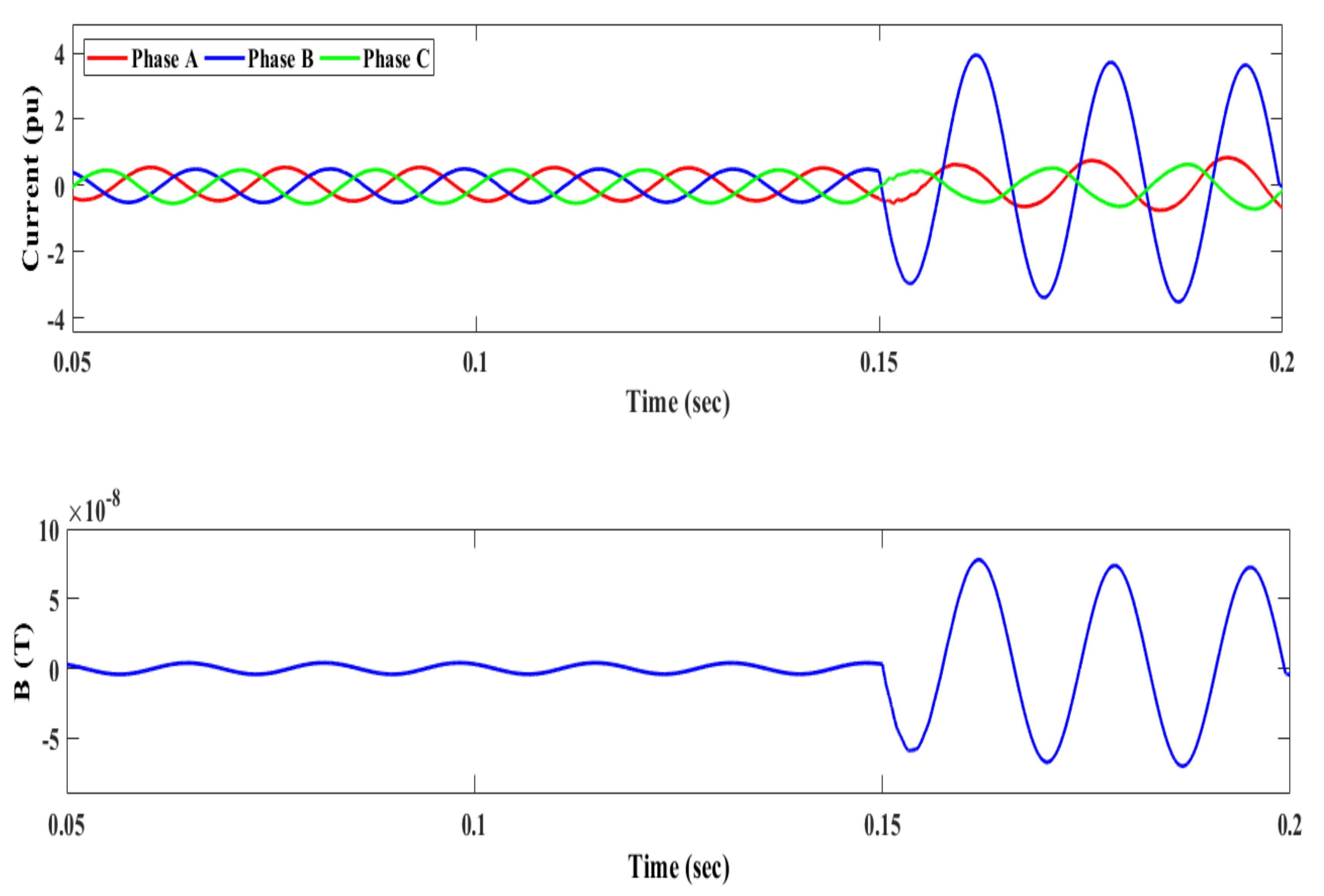
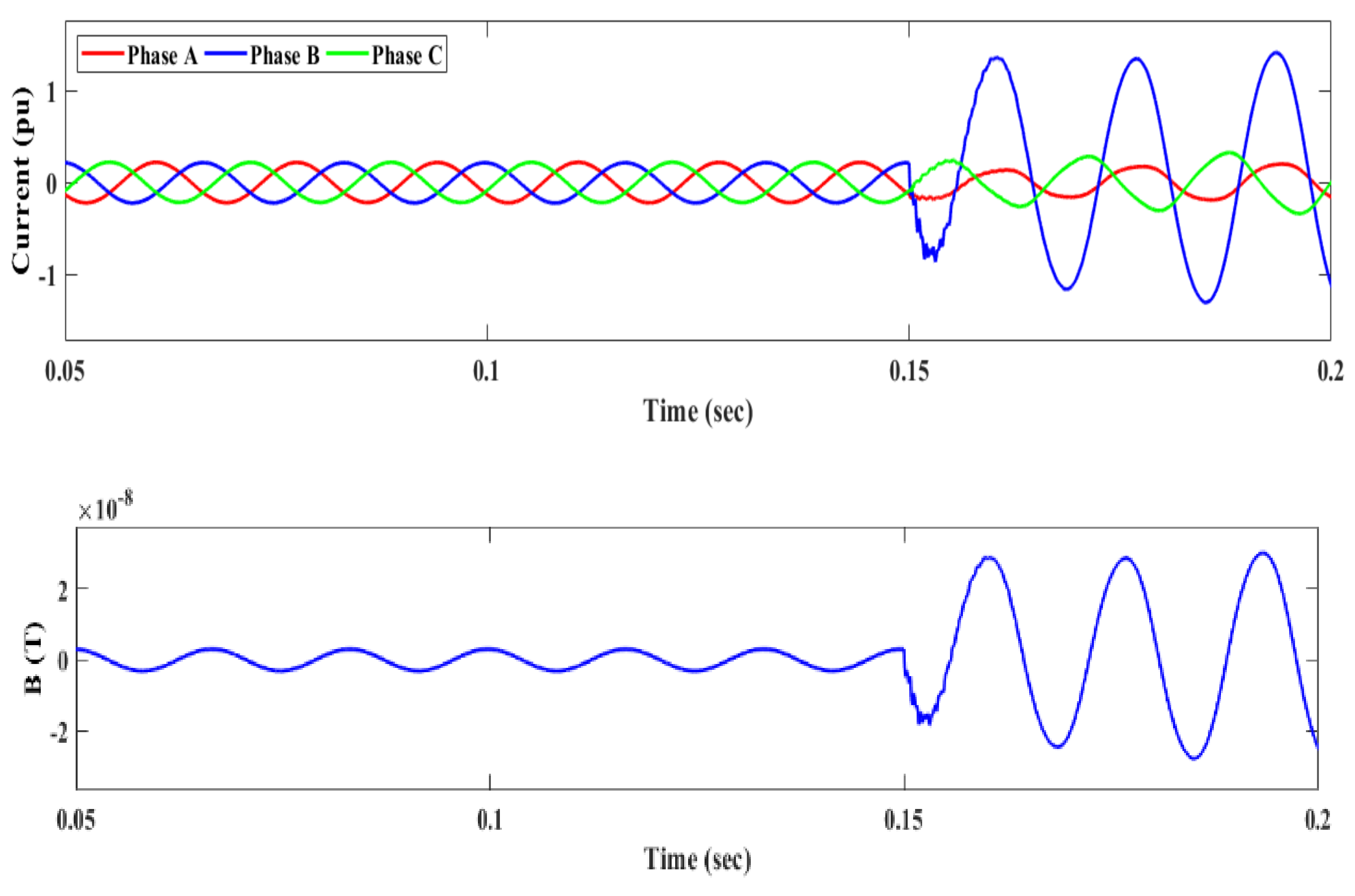
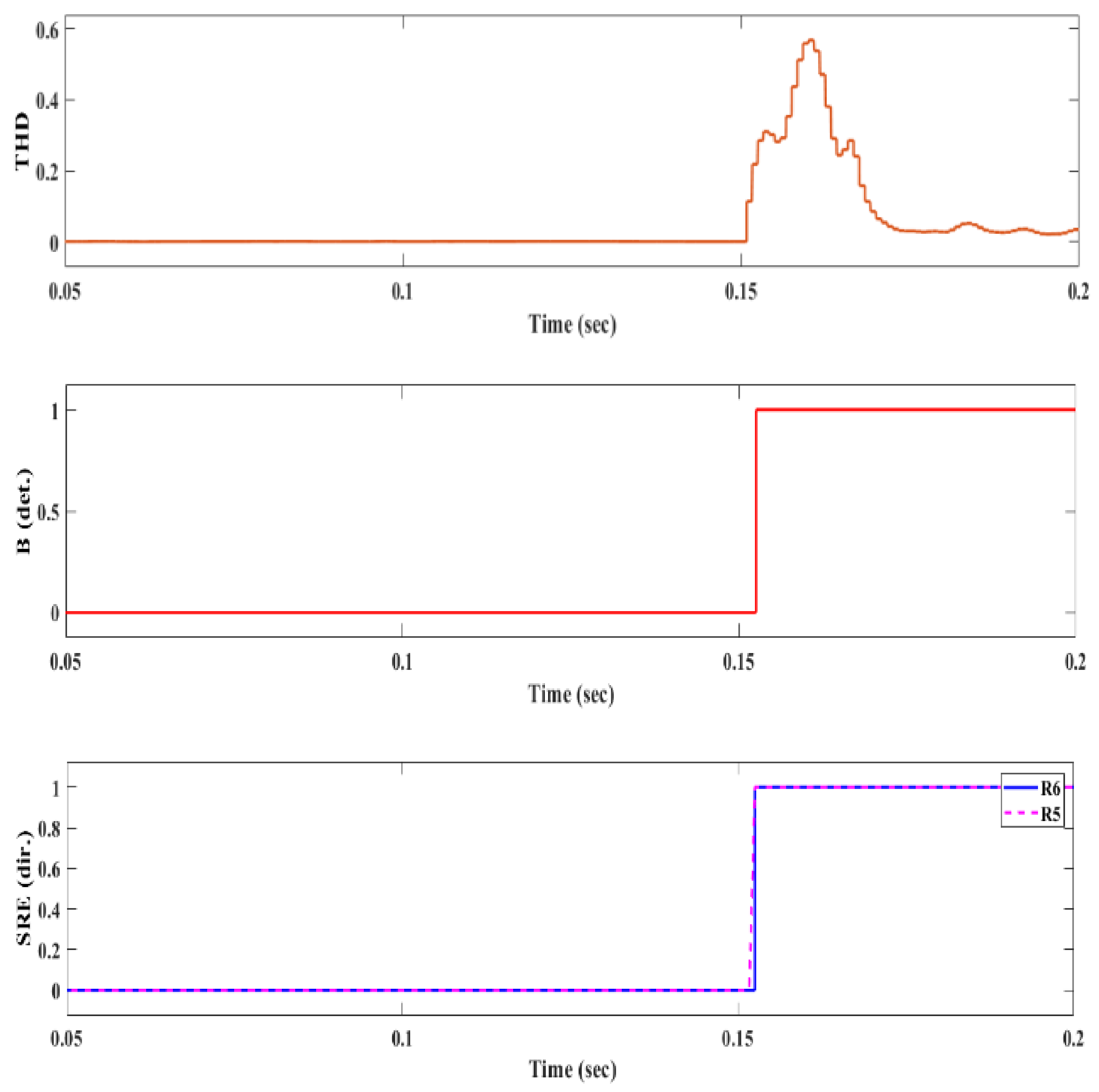
4.1. Fault Detection Scheme

To attest the effectiveness of the presented microgrid protection scheme in both grid-connected and islanded mode, exhaustive and vast simulations have been executed on MATLAB/SIMULINK software. The one-line diagram of the “Test Microgrid” is shown in Figure 7. The operating voltage of the micro-grid is 25 kV. A 120/25 kV DYg transformer is used to connect the microgrid with the main grid. The system consists of four DERs connected by power electronics converters, which include wind turbines, a photovoltaic system, a synchronous generator and energy storage devices. For the operation of all the DERs in both grid-connected and islanded mode, a droop control scheme is adopted. To investigate the efficiency of the proposed scheme, different types of faults were executed for all locations in the “Test Microgrid”. In this study, mainly solid faults are considered, which consist of LG faults, LLG faults, LL faults and three-phase faults. All fault cases were simulated in both grid-connected and islanded mode. The looped case is also considered by initializing the fault in different lines by closing CB loop-1 and CB loop-2. The load and network parameters are obtained from [32]. The case study parameters are shown in Table 3, whereas illustration of cases and configurations are demonstrated in Table 4.

4.1.1. Case Study 1: Grid Connected Mode

In the grid-connected mode, the system faces large transients during the fault as the utility grid is contributing large fault currents as compared to islanded mode. Fault signals are observed at DL-4 when a single line-to-ground current occurs on DL-2. Figure 8 shows current and magnetic field waveform measured at both ends of the distribution lines by the MR sensor mounted on the pole near the current-carrying conductors. The proposed protection scheme successfully trips and isolates the fault phase and section within 3.5 cycles.
The THD and SRE criteria are used for the detection and direction of faults. The figure indicates that the THD is higher than the pre-defined threshold value and hence the fault is detected. The fault signal on DL-2 is of forward type, as SRE is 1. Therefore, to trip the respective phase, primary protection will work and isolate the faulty phase by generating the trip signal based on calculations of superimposed components and activates the breaker as shown in Figure 8. The results show that the proposed scheme can distinguish the single-phase tripping incident, thus avoiding the tripping of healthy phases, hence improving system reliability.
To check the performance of the proposed protection scheme for line-to-line faults, an LL fault is initiated at DL-4 of the test microgrid. The fault current, magnetic field waveform and THD observed at Bus 4 are shown in Figure 9. THD is higher than the set criterion, i.e., 0.8. It is clear from the figure that the fault is of forward type after the fault initiation, as SRE is 1. The trip signal for the circuit breaker to isolate the faulty phases is depicted in Figure 9. In both mentioned cases, faults are initiated at different lines and distances; hence, it is proved that the proposed scheme can successfully clear faults with the change in conditions.

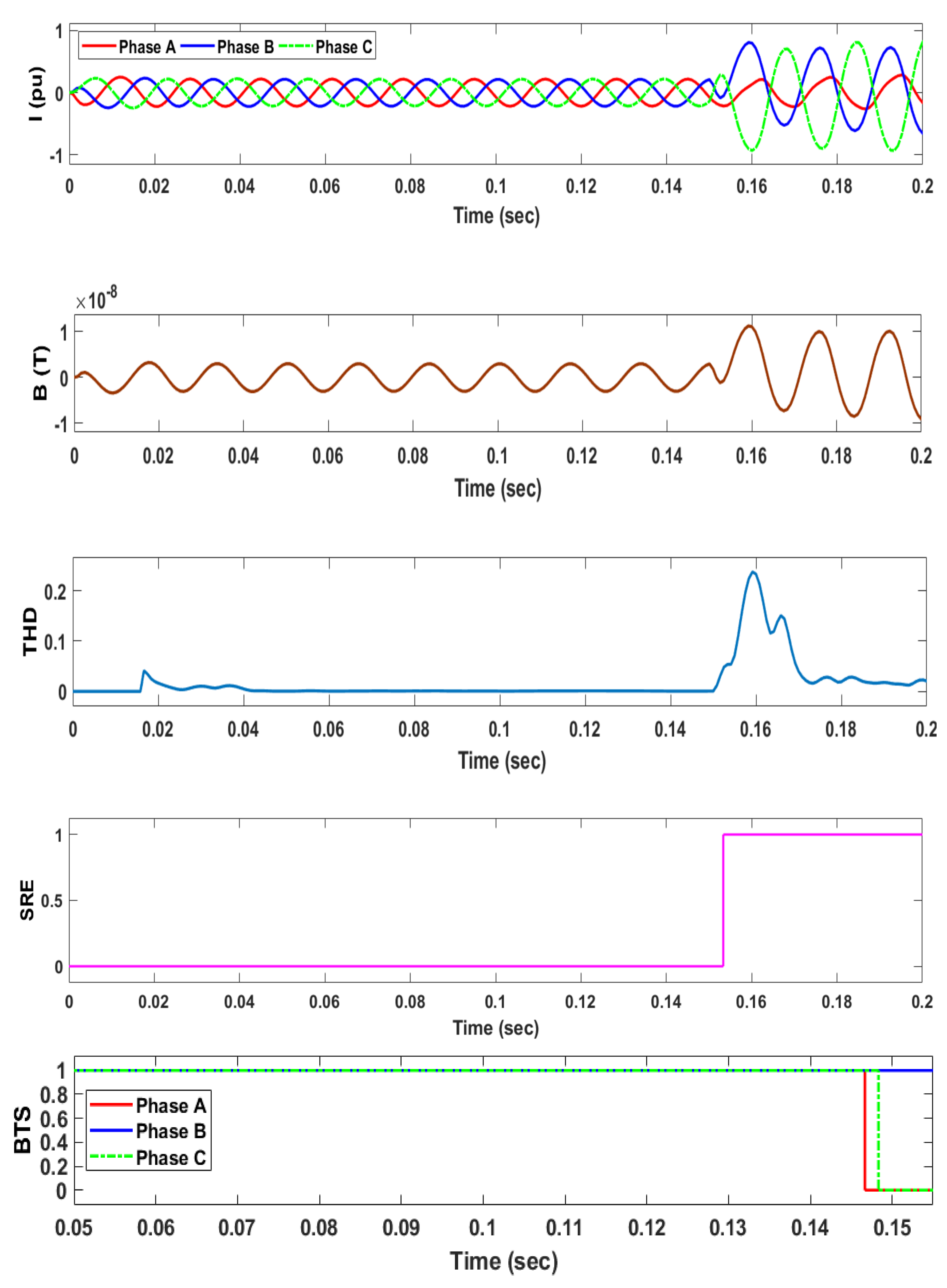
4.1.2. Case Study 2: Islanded Mode

One of the main challenges that affect the performance of protection techniques is the detection of low levels of fault currents in the islanded mode of operation. Usually fault currents during islanded mode are of comparable magnitude to load currents. To verify the operation of the proposed protection scheme, multiple faults have been initiated in the islanded mode also by opening the connection of breakers from the PCC. Figure 10 shows the current and magnetic field when an LG fault is observed at DL-5 of the test microgrid. On the basis of change in magnetic field at the time of fault, THD is calculated. The figure clearly shows that THD is higher than the set threshold value, indicating a fault situation. Moreover, Figure 11 indicates that the fault is forward at DL-5, as the relay at both ends of the line calculates SRE as “1”, indicating the faulty region of the system thus tripping the faulty phase by sending the trip signal to the circuit breaker. The trip signal generated for the circuit breaker is shown in Figure 11.
To validate and test the working of the protection scheme in islanded mode, three phase faults have also been examined at DL-2. As most of the DERs are iterative in nature, fluctuations have been noticed in the Figure 12 as the DERs’ output varies with time. Figure 12 and Figure 13 show the effectiveness of the proposed protection scheme. The results show that the proposed scheme can detect, localize and isolate faults within 3.5 cycles. Fluctuations in the output signals are due to the intermittent nature of the DERs, such as wind, solar panels, etc.

4.1.3. Case Study 3: Looped Configurations

The effectiveness of the proposed protection scheme is also tested in looped grid-tied configuration by initiating the LLG fault at DL-3. It is clear from Figure 14 that the proposed protection scheme can easily clear the fault. The THD and SRE signal for the fault shown in Figure 15 points out that it is higher than the set criterion, thus detecting the fault in DL-3 as forward and generating the trip signal to isolate the unhealthy phases.
An LG fault incident at DL-2 in islanded looped configuration is simulated. Figure 16 shows current and change in magnetic field waveform during the fault. Figure 17 presents that the designed methodology can effectively localize the fault and generate the trip signal within 3.5 cycles from occurrence of the fault.
Results reveal that the designed scheme works well with the looped configurations, having the capability of isolating the single phase effectively. Results demonstrate that the presented technique successfully operates in looped grid-connected mode as well as in islanded mode and isolates the fault within the set time of the protection scheme.

4.1.4. Case Study 4: Looped Configurations with Multiple DGs

The proposed strategy is also tested with multiple DGs connected at a time by changing the configuration of the microgrid during looped grid mode by closing the CB1 and CB2 shown in Figure 7. An LL fault is initiated at DL1. Figure 18 validates the results as the THD of magnetic field is higher than the set threshold value. Moreover, the results indicate that the fault is of forward type. Hence, the presented scheme can effectively trip the faulty phases by generating a trip signal from the circuit breaker within 3.5 cycles after the initiation of the fault.
Similarly, Figure 19 presents the results of the SLG fault during looped islanded mode, having two DGs connected at a time by opening the breaker from the PCC. The results show that the scheme works well with the set threshold criterion for fault detection and isolates the fault by keeping the healthy phases unaffected.

5. Comparative Analysis

The comparative analysis of LG faults during different modes of operations under looped scenarios, i.e., in grid-connected as well as in islanded mode, at DL-3 and DL-2 is shown in Figure 20 and Figure 21, respectively.
The results show that the presented scheme can effectively isolate the fault under different circumstances, and operates within the half cycle and successfully generates the breaker trip signal after 3.5 cycles.
Similarly, the LLL fault at DL-2 during looped grid-connected mode and the LL fault at DL-3 during looped islanded mode are shown in Figure 22 and Figure 23. In both configurations, the proposed scheme is effectively responding, hence showing the validity of the proposed scheme.

6. Conclusions

In this paper, a new protection scheme has been proposed to deal with the constraints in fault detection. The proposed scheme is capable of detecting and identifying the faulty incidents without any interruption or up-gradation of the current system in both grid-connected and islanded mode. The proposed protection scheme was divided into two main phases. In the first phase, identification of the fault was obtained based on variations in magnetic field levels around the current-carrying conductors. In the second phase, faults were classified by thresholding the superimposed components of the resultant current. SRE was utilized to find the direction of the fault which can localize it in the microgrid, in order to trip the circuit in a timely manner and thus isolate the faulty phases. The results prove that the proposed protection scheme safeguards microgrids against all types of faults with a single-phase tripping capability. In addition, the proposed protection scheme can protect microgrids in radial as well as looped configurations in both grid-connected and islanded modes. These tests were also conducted with multiple DGs and the scheme efficiently works in multiple configurations for both modes of operation. Furthermore, the proposed scheme is also capable of detecting and identifying faulty incidents without any interruption or up-gradation of the current system in both grid-connected and islanded modes. In future work, the proposed scheme will be implemented and tested for HIFs with minor design modifications. The scheme will be tested for backup protection in case the main protection fails to secure the system during faults or during the transition mode, i.e., from grid-connected to islanded mode and from islanded to grid-connected mode. Moreover, the improved variant will be simulated to test its efficiency on different larger systems with different configurations.

Author Contributions

Conceptualization, S.B.A.B.; methodology, M.M. and A.A; software, M.M. and S.A.A.K.; validation, Z.A.K., S.A.A.K. and D.R.S.; formal analysis, M.Y.; investigation, M.M., S.B.A.B. and S.A.A.K.; resources, A.A. and Z.A.K.; data curation, A.A and M.Y.; writing—original draft preparation, M.M., S.B.A.B. and S.A.A.K.; writing—review and editing, M.M., S.B.A.B., A.A., Z.A.K., S.A.A.K. and D.R.S.; visualization, M.M., Z.A.K. and S.A.A.K.; supervision, D.R.S., S.B.A.B. and S.A.A.K.; project administration, D.R.S., A.A. and Z.A.K.; funding acquisition, A.A and Z.A.K. All authors have read and agreed to the published version of the manuscript.

Funding

The main author extends his appreciation to the deputyship for Research & Innovation, Ministry of Education in Saudi Arabia for funding this research work through project number (IFP-2020-108).

Institutional Review Board Statement

Not applicable.

Informed Consent Statement

Not applicable.

Data Availability Statement

Not applicable.

Conflicts of Interest

The authors declare no conflict of interest.

Abbreviations

MR SensorsMagneto-Resistive Sensors
BMagnetic Field
DERDistributed Energy Resources
DG’sDistributed Generators
SRESuperimposed Reactive Energy
SIQSuperimposed Quantities
FFForward Fault
RFReverse Fault
MPMain Protection
BPBackup Protection
det.Detection
dir.Direction
ADCAnalog to Digital Converter
RRelay
ThresThreshold
IIDGInverter Interfaced Distributed Generator
BTSBreaker Trip Signal
HIFHigh Impedance Fault
GCMGrid-Connected Mode
ICMIslanded Mode
LGCMLooped Grid-Connected Mode
LIMLooped Islanded Mode
PCCPoint of Common Coupling

References

  1. Mathur, A.; Das, B.; Pant, V. Fault analysis of unbalanced radial and meshed distribution system with inverter based distributed generation (IBDG). Int. J. Electr. Power Energy Syst. 2017, 85, 164–177. [Google Scholar] [CrossRef]
  2. Tan, X.; Li, Q.; Wang, H. Advances and trends of energy storage technology in Microgrid. Int. J. Electr. Power Energy Syst. 2013, 44, 179–191. [Google Scholar] [CrossRef]
  3. Hatziargyriou, N.; Asano, H.; Iravani, R.; Marnay, C. Microgrids. IEEE Power Energy Mag. 2007, 5, 78–94. [Google Scholar] [CrossRef]
  4. Cagnano, A.; De Tuglie, E.; Mancarella, P. Microgrids: Overview and guidelines for practical implementations and operation. Appl. Energy 2019, 258, 114039. [Google Scholar] [CrossRef]
  5. Hussain, N.; Nasir, M.; Vasquez, J.C.; Guerrero, J.M. Recent Developments and Challenges on AC Microgrids Fault Detection and Protection Systems—A Review. Energies 2020, 13, 2149. [Google Scholar] [CrossRef]
  6. Kang, X.; Nuworklo, C.E.; Tekpeti, B.S.; Kheshti, M. Protection of micro-grid systems: A comprehensive survey. J. Eng. 2017, 2017, 1515–1518. [Google Scholar] [CrossRef]
  7. Mahamedi, B.; Fletcher, J.E. Trends in the protection of inverter-based microgrids. IET Gener. Transm. Distrib. 2019, 13, 4511–4522. [Google Scholar] [CrossRef]
  8. Brearley, B.J.; Prabu, R.R. A review on issues and approaches for microgrid protection. Renew. Sustain. Energy Rev. 2017, 67, 988–997. [Google Scholar] [CrossRef]
  9. Mirsaeidi, S.; Said, D.M.; Mustafa, M.W.; Habibuddin, M.H.; Ghaffari, K. An analytical literature review of the available techniques for the protection of micro-grids. Int. J. Electr. Power Energy Syst. 2014, 58, 300–306. [Google Scholar] [CrossRef]
  10. Brearley, B.J.; Raja Prabu, R.; Regin Bose, K.; Sankaranarayanan, V. Adaptive relay co-ordination scheme for radial microgrid. Int. J. Amb. Energy 2022, 43, 2180–2193. [Google Scholar] [CrossRef]
  11. Mirsaeidi, S.; Said, D.M.; Mustafa, M.W.; Habibuddin, M.H. A protection strategy for micro-grids based on positive-sequence component. IET Renew. Power Gener. 2015, 9, 600–609. [Google Scholar] [CrossRef] [Green Version]
  12. Langarizadeh, A.; Hasheminejad, S. A new differential algorithm based on S-transform for the micro-grid protection. Electr. Power Syst. Res. 2022, 202, 107590. [Google Scholar] [CrossRef]
  13. Li, X.; Dysko, A.; Burt, G.M. Traveling Wave-Based Protection Scheme for Inverter-Dominated Microgrid Using Mathematical Morphology. IEEE Trans. Smart Grid 2014, 5, 2211–2218. [Google Scholar] [CrossRef] [Green Version]
  14. Oureilidis, K.O.; Demoulias, C.S. A Fault Clearing Method in Converter-Dominated Microgrids with Conventional Protection Means. IEEE Trans. Power Electron. 2015, 31, 4628–4640. [Google Scholar] [CrossRef]
  15. Pinto, J.O.C.P.; Moreto, M. Protection strategy for fault detection in inverter-dominated low voltage AC microgrid. Electr. Power Syst. Res. 2020, 190, 106572. [Google Scholar] [CrossRef]
  16. Soleimanisardoo, A.; Karegar, H.K.; Zeineldin, H.H. Differential Frequency Protection Scheme Based on Off-Nominal Frequency Injections for Inverter-Based Islanded Microgrids. IEEE Trans. Smart Grid 2018, 10, 2107–2114. [Google Scholar] [CrossRef]
  17. Coffele, F.; Booth, C.; Dysko, A. An Adaptive Overcurrent Protection Scheme for Distribution Networks. IEEE Trans. Power Deliv. 2014, 30, 561–568. [Google Scholar] [CrossRef] [Green Version]
  18. Jayawarna, N.; Jones, C.; Barnes, M.; Jenkins, N. Operating microgrid energy storage control during net-work faults. In Proceedings of the 2007 IEEE International Conference on System of Systems Engineering, San Antonio, TX, USA, 16–18 April 2007; pp. 1–7. [Google Scholar]
  19. Beheshtaein, S.; Cuzner, R.; Savaghebi, M.; Golestan, S.; Guerrero, J.M. Fault location in microgrids: A communica-tion-based high-frequency impedance approach. IET Gener. Transm. Distrib. 2019, 13, 1229–1237. [Google Scholar] [CrossRef]
  20. Gao, H.; Li, J.; Xu, B. Principle and Implementation of Current Differential Protection in Distribution Networks with High Penetration of DGs. IEEE Trans. Power Deliv. 2016, 32, 565–574. [Google Scholar] [CrossRef]
  21. Saleh, S.A.; Ahshan, R.; Abu-Khaizaran, M.S.; Alsayid, B.; Rahman, M.A. Implementing and Testing d–q WPT-Based Digital Protection for Microgrid Systems. IEEE Trans. Ind. Appl. 2013, 50, 2173–2185. [Google Scholar] [CrossRef]
  22. Baloch, S.; Jamali, S.Z.; Mehmood, K.K.; Bukhari, S.B.A.; Zaman, M.S.U.; Hussain, A.; Kim, C.-H. Microgrid Protection Strategy Based on the Autocorrelation of Current Envelopes Using the Squaring and Low-Pass Filtering Method. Energies 2020, 13, 2350. [Google Scholar] [CrossRef]
  23. Jain, R.; Lubkeman, D.L.; Lukic, S.M. Dynamic Adaptive Protection for Distribution Systems in Grid-Connected and Islanded Modes. IEEE Trans. Power Deliv. 2018, 34, 281–289. [Google Scholar] [CrossRef]
  24. Jarrahi, M.A.; Samet, H.; Ghanbari, T. Novel Change Detection and Fault Classification Scheme for AC Microgrids. IEEE Syst. J. 2020, 14, 3987–3998. [Google Scholar] [CrossRef]
  25. Chakravorty, J.; Jain, A. Use of Magnetic Field Sensing Coils for Fault Location in Transmission Lines. Int. J. Emerg. Trends Eng. Dev. 2012, 4, 566–576. [Google Scholar]
  26. Khawaja, A.H.; Huang, Q.; Lian, L. Experimental study of Tunnel and Anisotropic Magnetoresistive sensor for power system magnetic field measurement applications. In Proceedings of the 2015 IEEE 3rd International Conference on Smart Instrumentation, Measurement and Applications (ICSIMA), Kuala Lumpur, Malaysia, 24–25 November 2015; pp. 1–5. [Google Scholar] [CrossRef]
  27. Huang, Q.; Zhen, W.; Pong, P.W. A novel approach for fault location of overhead transmission line with noncontact magnetic-field measurement. IEEE Trans. Power Deliv. 2012, 27, 1186–1195. [Google Scholar] [CrossRef]
  28. Kazim, M.; Khawaja, A.H.; Zabit, U.; Huang, Q. Fault Detection and Localization for Overhead 11-kV Distribution Lines with Magnetic Measurements. IEEE Trans. Instrum. Meas. 2019, 69, 2028–2038. [Google Scholar] [CrossRef]
  29. Salari, J.C.; Mpalantinos, A.; Silva, J.I. Comparative Analysis of 2- and 3-D Methods for Computing Electric and Magnetic Fields Generated by Overhead Transmission Lines. IEEE Trans. Power Deliv. 2008, 24, 338–344. [Google Scholar] [CrossRef]
  30. Benmouyal, G.; Roberts, J. Superimposed quantities: Their true nature and application in relays. In Proceedings of the 26th Annual Western Protective Relay Conference, Spokane, WA, USA, 26–28 October 1999. [Google Scholar]
  31. Bukhari, S.B.A.; Zaman, M.S.U.; Haider, R.; Oh, Y.-S.; Kim, C.-H. A protection scheme for microgrid with multiple distributed generations using superimposed reactive energy. Int. J. Electr. Power Energy Syst. 2017, 92, 156–166. [Google Scholar] [CrossRef]
  32. Kar, S.; Samantaray, S.R.; Zadeh, M.D. Data-Mining Model Based Intelligent Differential Microgrid Protection Scheme. IEEE Syst. J. 2015, 11, 1161–1169. [Google Scholar] [CrossRef]
Figure 1. Configuration of current-carrying conductors.
Sustainability 15 00599 g001
Figure 2. Magnetic field at sensor’s point due to current in phases a, b and c.
Sustainability 15 00599 g002
Figure 3. Magnetic Field at Sensor point.
Sustainability 15 00599 g003
Figure 4. Protection zones of proposed protection scheme.
Sustainability 15 00599 g004
Figure 5. Flow chart of proposed protection scheme.
Sustainability 15 00599 g005
Figure 6. Schematic diagram of proposed protection scheme.
Sustainability 15 00599 g006
Figure 7. Single-line diagram of test microgrid.
Sustainability 15 00599 g007
Figure 8. SLG Fault (50%) at DL-2 during grid-connected mode.
Sustainability 15 00599 g008aSustainability 15 00599 g008b
Figure 9. LL fault (40%) at DL-4 during grid-connected mode.
Sustainability 15 00599 g009aSustainability 15 00599 g009b
Figure 10. LG fault at (60%) DL-5 observed during islanded mode.
Sustainability 15 00599 g010
Figure 11. LG fault at DL5 during islanded mode.
Sustainability 15 00599 g011aSustainability 15 00599 g011b
Figure 12. LLL fault at DL-2 observed at Bus 5 during islanded mode.
Sustainability 15 00599 g012
Figure 13. LLL fault at DL-2 during islanded mode.
Sustainability 15 00599 g013
Figure 14. Current and Magnetic field waveform of LLG fault at DL-3 during looped grid-connected mode.
Sustainability 15 00599 g014aSustainability 15 00599 g014b
Figure 15. THD, detected signal and SRE of LLG fault at DL-3 during looped grid-connected mode.
Sustainability 15 00599 g015
Figure 16. Current and Magnetic field waveform of LG fault at DL-2 during looped islanded mode.
Sustainability 15 00599 g016
Figure 17. THD, detected signal and SRE of LG fault at DL-2 during looped islanded mode.
Sustainability 15 00599 g017aSustainability 15 00599 g017b
Figure 18. LL fault at DL-1 during grid-connected mode with 2 DERs connected at a time.
Sustainability 15 00599 g018aSustainability 15 00599 g018b
Figure 19. LG fault at (20%) DL-3 during islanded mode with 2 DERs connected at a time.
Sustainability 15 00599 g019aSustainability 15 00599 g019b
Figure 20. LG fault at DL-3 during grid-connected looped mode.
Sustainability 15 00599 g020aSustainability 15 00599 g020b
Figure 21. LG fault at DL-2 at isolated looped mode.
Sustainability 15 00599 g021aSustainability 15 00599 g021b
Figure 22. LLL fault at DL-2 during grid-connected looped mode.
Sustainability 15 00599 g022
Figure 23. LL fault at DL-3 during isolated looped mode.
Sustainability 15 00599 g023
Table 1. Output of fault detection and direction signals.
Signal10
B (det.)Fault DetectedNo Fault
R (dir.)FFRF
Table 2. MF threshold values at different modes of operation.
OperationThreshold
Faulted Grid0.08
Faulted Islanded
Faulted Looped Configuration
Table 3. Case study parameters.
Grid Parameter DescriptionParameter DesignationParameter Value
VoltageV25 kV
Frequencyf60 Hz
DG’s Specifications PV/Wind DGDER13 MW (Inverter based)
PV/Wind DGDER 2–32 MW IIDG
Sync GeneratorDER46 MW Sync Generator
Line Parameters DL1- DL6L20 km
VoltageV base25 kV
Load Parameters∑ L1-L615 MW; 5.5 MVAR
Table 4. Illustration of cases and configurations.
Case Study #Case #Mode Description/Configuration
1Case 1Grid Connected/Radial
2Case 2Islanded/Radial
3Case 3Grid Connected/Loop
Case 4Islanded/Loop
4Case 5Grid Connected/Loop(2 DER’s)
Case 6Islanded/Loop(2 DER’s)
Disclaimer/Publisher’s Note: The statements, opinions and data contained in all publications are solely those of the individual author(s) and contributor(s) and not of MDPI and/or the editor(s). MDPI and/or the editor(s) disclaim responsibility for any injury to people or property resulting from any ideas, methods, instructions or products referred to in the content.

