Review

Floating Photovoltaic Plant Monitoring: A Review of Requirements and Feasible Technologies

by
Silvia Bossi
1,†,
Luciano Blasi
1,†,
Giacomo Cupertino
1,†,
Ramiro dell’Erba
1,
Angelo Cipollini
1,
Saverio De Vito
2,
Marco Santoro
1,
Girolamo Di Francia
2,* and
Giuseppe Marco Tina
3
1
Research Centre of Casaccia, ENEA—Italian National Agency for New Technologies, Energy and Sustainable Economic Development, Via Anguillarese, 301, 00123 Roma, Italy
2
Research Centre of Portici, ENEA—Italian National Agency for New Technologies, Energy and Sustainable Economic Development, P. le E. Fermi, 1, 80055 Napoli, Italy
3
Department of Electric, Electronic and Computer Engineering, University of Catania, v. le A. Doria no. 6, 95125 Catania, Italy
*
Author to whom correspondence should be addressed.
These authors contributed equally to this work.
Sustainability 2024, 16(19), 8367; https://doi.org/10.3390/su16198367
Submission received: 22 July 2024 / Revised: 14 September 2024 / Accepted: 18 September 2024 / Published: 26 September 2024
(This article belongs to the Special Issue Sustainable Energy Systems and Applications)

Abstract

:
Photovoltaic energy (PV) is considered one of the pillars of the energy transition. However, this energy source is limited by a power density per unit surface lower than 200 W/m2, depending on the latitude of the installation site. Compared to fossil fuels, such low power density opens a sustainability issue for this type of renewable energy in terms of its competition with other land uses, and forces us to consider areas suitable for the installation of photovoltaic arrays other than farmlands. In this frame, floating PV plants, installed in internal water basins or even offshore, are receiving increasing interest. On the other hand, this kind of installation might significantly affect the water ecosystem environment in various ways, such as by the effects of solar shading or of anchorage installation. As a result, monitoring of floating PV (FPV) plants, both during the ex ante site evaluation phase and during the operation of the PV plant itself, is therefore necessary to keep such effects under control. This review aims to examine the technical and academic literature on FPV plant monitoring, focusing on the measurement and discussion of key physico-chemical parameters. This paper also aims to identify the additional monitoring features required for energy assessment of a floating PV system compared to a ground-based PV system. Moreover, due to the intrinsic difficulty in the maintenance operations of PV structures not installed on land, novel approaches have introduced autonomous solutions for monitoring the environmental impacts of FPV systems. Technologies for autonomous mapping and monitoring of water bodies are reviewed and discussed. The extensive technical literature analyzed in this review highlights the current lack of a cohesive framework for monitoring these impacts. This paper concludes that there is a need to establish general guidelines and criteria for standardized water quality monitoring (WQM) and management in relation to FPV systems.

1. Introduction

Electricity produced by photovoltaic systems represents one of the central pillars for the energy transition, supposed to account for about 50% of the global electric energy balance by 2050, becoming prevalent and dominant in the Southern Europe region, together with wind energy in Europe as a whole, as well illustrated by Nijsse and co-authors in [1].
One of the major problems connected with the massive diffusion of this energy source is its low density of power installable per unit of surface area compared to conventional fossil sources, with an average energy produced per year and per unit of surface area which is 10–100 times lower than that produced, for example, by means of natural gas [2]. In the current state of photovoltaic sector technology, the power capacity that can be installed per m2, even in the most favorable installation conditions, does not exceed 200 W/m2 [3]. In these conditions, the diffusion of photovoltaic energy can imply a significant use of land areas, raising questions of competition with other land uses, such as agricultural uses. This opens ethical debates, since photovoltaic diffusion could create competition between the production of a good that is more relevant for richer countries, i.e., energy at the expense of another, e.g., food, which is still insufficient in many poor countries [4,5].
In this context, the use of floating photovoltaics, which is characterized by photovoltaic systems built on water basins, including offshore areas, appears to be a particularly interesting solution to the aforementioned dichotomy since it could lead to a reduction in land consumption by approximately three times for photovoltaic system installation [6]. This may happen not only because FPV technology is potentially compatible with open sea offshore installations, with evidently no main conflicting problems with other area uses, but also due to the exploitation of internal basins, such as abandoned quarries, which generally have no other possible uses [7].
Floating photovoltaics have a relatively recent history, the first systems having been built less than 20 years ago [8], but it is receiving rapid and growing interest, as will be better discussed in paragraph 2. In addition to the issue of the indirect saving of land areas mentioned above, the reasons for this growth can be attributed to specific advantages of this technology:
  • Better average PV system efficiency due to the mitigating thermal effect resulting from the thermal capacity of the water [9];
  • Indirect effect of water evaporation minimization [10];
  • Shorter installation times compared to ground-based systems [11];
  • Higher power density as compared to ground-based systems [12].
As mentioned above, paragraph 2 of this work is devoted to a review of floating PV technologies, mainly focused on inner water basins; paragraph 3 discusses more specifically issues related to monitoring technology related both to the part of an FPV plant above the surface of the water, and the one correlated to the quality of the water; paragraph 4 is a review of the sensors that can be used, in particular for monitoring water quality; in paragraph 5, the problems related to the autonomous monitoring of water quality are discussed; in paragraph 6, possible autonomous systems for monitoring water basins for photovoltaic use are proposed and analyzed; discussions are reported in paragraph 7, while the conclusions will be drawn in paragraph 8.

2. PV Floating Plants

PV modules are generally installed over the ground and rooftops using rigid mounting structures, whose technical and economic issues are well assessed in the literature [13]. However, due to limited land availability, dense populations, and significant deforestation threats, there is increasing interest in installing photovoltaic modules over water bodies such as canals, lakes, reservoirs, and oceans. These installations are generally referred to as water-based photovoltaics (WPVs), which include floating freshwater PV, offshore PV, underwater PV, and canal-top PV systems [14].
Specifically, according to [15], floating photovoltaic systems can be divided into four types: pile-based, floating, tracking systems, and water level variation systems. The first three types are mainly used in shallow water bodies with stable water levels and calm surfaces, such as lakes (including saltwater lakes), rivers, and fishponds. The last category, water level variation systems, is designed for use in reservoirs with significant water level fluctuations, such as pumped storage reservoirs. It is also possible to integrate tracking systems into both floating and pile-based PV systems [16,17]. It is worth noting that evaporation reduction, in this case, directly translates into energy efficiency savings, for obvious reasons.
Recently, there has also been increasing interest in offshore FPV solutions, with the first offshore FPV system established in the Netherlands in 2017, a decade after the first FPV system in Japan [18,19]. Despite the challenging operating conditions of marine FPV systems, such as high waves, high winds, and a corrosive atmosphere, industrial and research institutions are actively working to develop and enhance various FPV solutions for marine environments. These marine FPV systems differ significantly from freshwater FPV systems and aim to achieve adequate operational safety and cost-efficiency [20].
A schematic view of an FPV system is shown in Figure 1, its key components being a floating platform, mooring and anchoring systems, PV modules, electric cables, and connectors [21]. Notably, a lightning protection system is also present.
The threat of lightning to floating photovoltaic power plants arises from several factors. Firstly, their location in open areas, such as the surface of a water reservoir, poses a significant risk. Additionally, the sharp upper edges of the photovoltaic modules, which are mounted at an angle on supporting structures, concentrate the electric field. This concentration can increase the likelihood of a lightning strike hitting one of the modules [22].
The floating platform is the most crucial component of floating photovoltaic systems. It supports all components of PV generators and as well as the supporting structure (when used), and furthermore provides the right buoyancy, including a space for human accessibility, also considering operating conditions (high wind, waves, and when applicable, snow weight). Hence, the choice of the design and related material is fundamental. Floating platforms are mostly made of high-density polyethylene (HDPE), which is UV-resistant, corrosion-resistant, and has a high tensile strength, but there are other materials available, such as medium-density polyethylene (MDPE), fiber-reinforced plastic (FRP), and ferro-cement [23,24]. From the design point of view, floating platforms can be categorized, as reported in [25] as pure float, which is made of shaped floats that can hold PV modules directly, and pontoon plus a metal structure, which uses a metal structure to connect the elements that provide buoyancy by means of metallic elements (the PV modules are held by a metallic structure similar to PV land-based system). As stated in [20], using flexible crystalline silicon-based modules backed with foam may be less expensive than pontoon-based FPV systems. Ocean Sun technology lays rigid crystalline silicon modules on a reinforced flexible membrane. The operating temperature of the module is reduced due to direct heat transfer into the water below, exhibiting higher yields than standard air-cooled systems. Buoyancy is obtained by an HDPE ring that encloses the membrane. In all described floating solutions, rigid PV modules are used. An alternative approach using flexible thin-film photovoltaic technologies has been demonstrated, employing foams for flotation [26,27]. The PV modules are positioned so close to the water that waves clean the panels of dust and provide additional cooling. Using foam for flotation significantly reduces the cost per watt of the racking system.
The floating structures need to be moored for several reasons [28]:
1.
To keep floating solar arrays within reasonable proximity of a target location (station keeping).
2.
To minimize the movement of solar arrays caused by environmental forces such as winds, waves, and currents.
3.
To maintain a minimum distance between solar arrays.
4.
To cope with varying water levels.
5.
Finally, the design of mooring systems must address the following challenges:
  • A large number of mooring lines (especially in the case of pure float designs).
  • Site constraints.
  • Varying water levels.
  • Unequal load distribution.
  • Array shape and size.
Rigid supports in the form of anchorages are provided using plinths at the bottom of the reservoir to manage dead loads and lateral forces [29]. In 2021, DNV recommended practices for designing floating PV mooring systems in freshwater [30]. While these recommendations provide a good technical reference, significantly larger environmental loads in marine environments need to be fully considered [19].

3. PV Floating Monitoring Issues

3.1. Monitoring FPV Systems for Evaluating the Water Environment Impact on Energy Production

The interactions between an FPV system and the aquatic environment must be closely observed and monitored from both perspectives: the impact of water on the floating system, and conversely, the impact of the floating system on the aquatic environment. In this paragraph, the first case is considered.
The interactions to be monitored, considering the environmental influence on FPV systems, include:
  • Positioning of the PV Modules: The position of the photovoltaic (PV) modules can be affected by wave movements, which vary significantly depending on whether the system is located offshore or in freshwater basins, as well as the type and design of the anchoring system. Consequently, the modules exhibit variable positioning.
  • Temperature of the PV Modules: The temperature of the PV modules is affected by their surrounding microclimate, in turn depending on the water temperature and the thermo-hygrometric conditions induced by the presence of water.
  • Efficiency Degradation of the PV Modules over time. The hygrometric conditions in which the PV modules operate can impact their efficiency over time, potentially leading to a loss of performance.
Considering the aforementioned factors, additional environmental and operational measurements are essential for monitoring an FPV system. These measurements are crucial not only for assessing the system’s short- and long-term energy performance but also for ensuring its safety and reliability.

3.1.1. Variable Module Positioning

The variation in the position of FPV modules over time due to the effect of water waves results in energy losses, which are currently measured and investigated by various models [31]. These measurements are also crucial for ensuring the safety of the anchoring mechanisms of the floating photovoltaic system itself.
Unlike land-based systems, floating systems may experience pitch, yaw, and roll movements similar to those of a properly anchored vessel, as shown in Figure 2, where the conventions used for ship movements are adopted.
The various rotations can be identified through direct measurements using accelerometers; see [33]. For instance, an inertial measurement unit (IMU) Ellipse-E from SBG was attached to a panel to measure its roll, pitch, and angular velocities, as has been reported in [34]. For offshore plants, indirect measurements related to wave motion are highly complex [35]. Wind speed and direction measurements, when combined with wave motion data, can be converted into the motion of the floating platform using algorithms based on artificial intelligence.
Another indirect measurement approach involves comparing global radiation measurements taken on the ground on the theoretical plane of the modules (assuming a perfectly flat water surface) with those on the floating platform. The discrepancies between these measurements can be translated into misalignment angles between a ground-based module with a fixed orientation and a floating module. In this context, the difference in albedo between terrestrial and aquatic environments should be considered as a bias when evaluating the actual losses due to the movement of the floating platform. To mitigate this issue, installing two pyranometers (one on the ground and the other on the floating system) horizontally could minimize the albedo problem as much as possible. Additionally, a GPS receiver and a geomagnetic sensor solution, as used in [36], could provide valuable data for monitoring the movements of FPV systems.

3.1.2. PV Module Temperature

The temperature of floating photovoltaic modules is affected by the different operating conditions compared to those on the ground, due to both the proximity of the water and the different wind conditions (soil roughness factor). Therefore, to evaluate the cell temperature by means of mathematical models, additional measurements of the local environmental variables will have to be carried out, specifically ambient temperature and wind speed, which may depend on the size of the basin and may be different compared to locations on land. In particular, water temperature is particularly important, as it has been included in multivariate regression models [37]. Vice versa, the role of humidity on cell temperatures, which could be important for FPV, has not been extensively studied [38], apart from by Peters and Nobre [39], who consider relative humidity to calculate the contribution of cooling by radiative exchange. In their model, Tina et al. [40] took vapor pressure into account to calculate the apparent temperature of the model. Other researchers, however, fully neglected the impact of relative humidity [41].

3.1.3. Loss of Efficiency of PV Modules Over Time

The combination of high temperatures and high relative humidity has been shown to significantly impact the performance loss rate (PLR) of photovoltaic (PV) modules. In environments with relative humidity exceeding 70%, the risk of moisture penetration increases, leading to greater corrosion of metal joints, necrosis of the polymer, and yellowing of its color [42].
However, initial experimental evidence from the largest testbed of FPV systems currently in operation, located in the Tengeh Basin (Singapore), a tropical climate location, indicates that over a three-year observation period, the PLRs of floating systems are comparable to those of a rooftop reference system installed near the basin [43].

3.1.4. Effects of Soiling on FPV

In the case of floating photovoltaic systems, the effect of the basin water quality on the cleanliness of the PV modules remains almost completely underestimated. The soiling phenomenon affecting photovoltaic systems performances is well known and several reviews have been published on the topic [44]. It is, moreover, well known that soiling-related economic losses can be very relevant, especially in those cases where the photovoltaic energy production system coexists with other production activities, such as those connected to agricultural crops [45].
As regards FPV in particular, it should also be considered that in the soiling mechanism, the role of water, mainly intended in terms of a humidity rate, is of the utmost relevance; in environments with a high humidity, consolidation phenomena of material residues affecting the electrical conversion efficiency might occur more frequently [46]. Extrema in these cases can be observed in the case of marine waters where, power limitations higher than 10% have actually been observed, suggesting that FPV systems could be subject to severe reductions in the power generated [47]. Finally, in environments characterized by poor water quality, it has been observed that the cleaning efficiency due to the mechanical action of the water itself may be quite limited and that, therefore, water quality could also play a role in energy production [48].

3.1.5. Monitoring via UAV

Unmanned aerial vehicle (UAV) monitoring systems for photovoltaic installations have reached a level of full maturity. However, marine applications [49], particularly floating photovoltaics (FPV) and offshore systems [19] present novel challenges that necessitate further advancements in UAV monitoring techniques. The monitoring of FPV systems by UAVs encounters specific difficulties due to the aquatic environment and the anchoring mechanisms of the infrastructure. Previously unaddressed issues can emerge with FPVs, such as optical disturbances affecting sensors due to sunlight reflections and wave glints. Additionally, controlling the UAV’s attitude and stability may be more challenging due to stronger wind gusts. Take-off, landing, and navigation become more difficult because of the random relative motion of the pontoons. These factors may necessitate additional maneuvers, thereby reducing the UAV’s operational autonomy.
Navigation complexity increases with FPV systems, since the floating structure is in constant motion. Even with perfect GPS positioning of the UAV, its relative position to the FPV remains uncertain. This uncertainty requires frequent verification of the GPS position and orientation of the FPV, considering its continuous random rotation along the axes, which imposes a significant real-time computational burden. Nonetheless, non-GPS navigation systems, such as optical navigation and microwave radar sensors, are available.
Finally, issues related to the quality of the images acquired by UAVs during FPV monitoring may arise. Sunlight reflection and glint can significantly impact vision-based object detection in marine environments. Rapid course corrections can limit the areas affected by reflections.

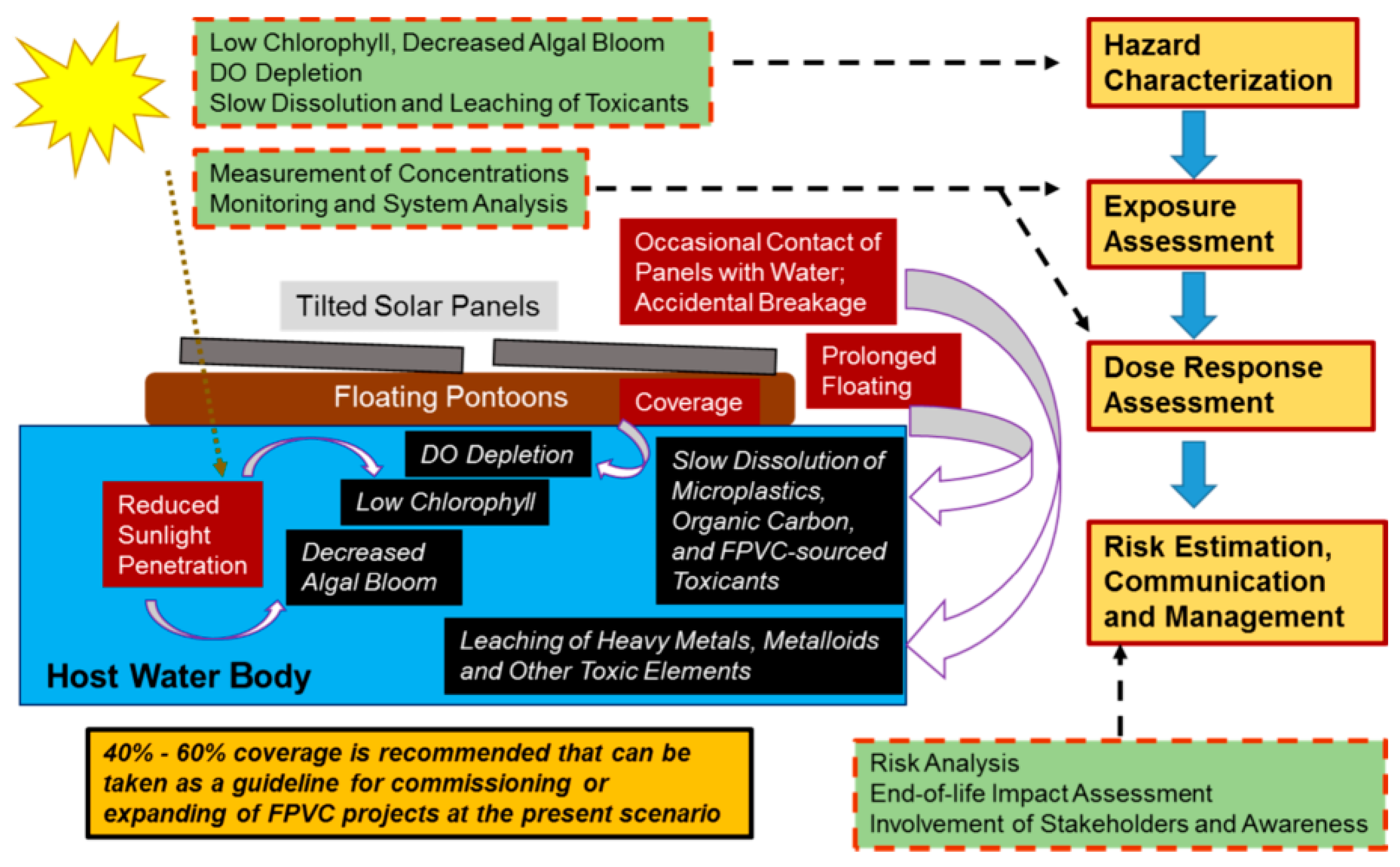
3.2. Monitoring FPV Systems for Evaluating Their Impact on Water Ecosystem

The exponential growth observed in the installation of residential, commercial, and industrial photovoltaic systems has resulted in a debate on the potential environmental risks associated with such a widespread diffusion of this renewable energy technology [50]. As a matter of fact, the debate is backed by assumptions which are often unfounded. Nevertheless, these might risk slowing down the energy transition process, as has been recently discussed, for example, by Mirletz and coauthors with respect to the problem of special waste that would be produced by the diffusion of this type of technology [51].
On the other hand, photovoltaic systems built on lands used for agricultural crops or, as discussed here, floating plants built on water basins show their own peculiarities, since in both such cases, the problem is to evaluate the potential negative effects that such installations may have on complex environmental and ecological systems. Given that both agrivoltaics and floating photovoltaics are rather new application sectors, it should not seem strange that the points of view on the topic can still be very different. As an example, Gunerhan and coauthors list in their work a series of negative elements related to the diffusion of solar photovoltaics [52] and in the case of floating photovoltaics, environmental modeling works have, for example, suggested negative effects on phytoplankton concentrations, which increase with the area of the reservoir covered by the photovoltaic system [53]. However, in most of the cases reported and discussed in the literature, floating photovoltaic systems do not currently have any type of monitoring system installed that could allow us to actually evaluate possible negative (or positive) effects on the environment, which makes the discussion rather undefined [54,55]. The problem is, therefore, determining which are the water parameters that need to be kept under control at the installation site of a floating photovoltaic system, and also, how to carry out the sampling itself. As a matter of fact, all the guidelines that have been published so far up to now on this topic [56,57] suggest carrying out a series of measurements ex ante, during plant operation and after its decommission, evaluating the water parameters reported in Table 1.
Therefore, if there is a general consensus on what should be monitored in an FPV plant, the issues of first “where” and second “how” to measure such parameters seems to be much less defined. Figure 3 shows a diagram of the possible contamination processes and of the consequent environmental risks associated with the installation of a photovoltaic system on a reservoir.
As can be seen from the possible contamination paths highlighted in Figure 3, in general, it should be necessary to monitor water quality immediately under the floating photovoltaic system at various depths and to compare the observed values with those of samples collected relatively far away from it. This is in fact the general approach followed in all works published in the literature. There are, however, differences regarding how such measurements have to be carried out. Atikah and co-authors [66] carry out measurement campaigns by means of static systems for water sample collection, displaced immediately near and below the plant, which are then analyzed in the laboratory. A similar technique is used by the authors in refs. [63,64] and also in ref. [67]. Always static but by means of the use of multiparametric probes is the approach proposed by Vlaswinkel and co-authors in ref. [68], which is therefore advantageous in terms of a more timely water analysis.
On the contrary, Rui L. Pedroso de Lima [69] and co-authors propose the use of robotic systems for the control of multiple points both under the FPV plant and at a distance from it, suggesting that the measurements should be carried out in multiple points, immediately below the plant and away from it (100 m in the specific case studied by the authors) and at depths such as to cover the full water column. It is interesting to underline that such a monitoring approach, by means of automatic systems, has also been proposed in other scenarios. More generally, unmanned systems for aquaculture have been discussed in [70] and they have also been proposed for the case of floating buildings [71].
Finally, it is interesting to recall here an innovative approach, although not related to FPV plants but to fish farms, proposed by Chatziantoniou and co-authors, in which satellite data and local data are combined to obtain real-time modeling of reservoir conditions [72].

4. Sensors for Water Quality Monitoring

Proper water quality monitoring (WQM) is necessary before installation, during operation, and after decommissioning of an FPV to investigate its environmental impact [26]. This paragraph provides an overview of commercial off-the-shelf sensors used for water quality monitoring in research applications.
Water bodies can be monitored using static sensors submerged at fixed locations and depths (fixed sensors), or by using underwater robots with integrated onboard sensors (mobile sensors), or, finally, by collecting water samples for laboratory analysis. The first two approaches are preferred to increase the autonomy of water monitoring activities, and benefit from compact and lightweight sensors. It is worth noting though, that the general tradeoff involving spatial and temporal sampling frequency when considering mobile and fixed monitoring stations is also relevant. Mobile platforms are capable of increased and readily tunable spatial coverage and density, while fixed stations offer better temporal density performances. Cost considerations may heavily impact the choice.
The preferred sensing approaches generally rely on multiparametric probes consisting of a main body with a data logger and inputs for multiple sensor integrations, enabling simultaneous or consecutive measurement of several parameters such as temperature (T), conductivity (σ), dissolved oxygen (DO), turbidity (NTU/FNU), pH, light intensity (I), and chlorophyll-a (Chl-a). A depth or pressure sensor is also required to normalize measurements with specific depths in the water column. Some multiparametric probes are also equipped with wipers to clean the sensor regularly, reducing maintenance efforts by lowering the post-deployment intervention frequency. As we have seen, water body monitoring can be implemented through fixed, networked installations or with the use of underwater vehicles. The dimensions and weight of the probes can impact the maneuverability of underwater vehicles [73] as well as the positioning in fixed networked deployments. For this reason, compact and light probes have evident advantages for both uses (fixed and mobile). The maximum operating depth of the sensors varies depending on the model and manufacturer. FPV installation can occur in water bodies of varying depths. According to the literature, WQM under FPV has been performed at different nodes of selected water columns, reaching the bottom of the water body (Pedroso de Lima 2021). Thus, a multiparametric probe has to take into account the maximum depth of the water body to be monitored.
Here, the scientific literature using multiparametric probes for WQM in FPV installations has been reviewed. The cited multiparameter probes, their manufacturers, their sensors, and their main features are summarized in Table 2, where additional papers on general WQM (not specific to FPV) were included for the sake of completeness. The review identified six papers that used nine different multiparameter probes (EXO3, YSI 6920, QAM300-DE, UltraPen PT1, Troll 9500, CTD Diver, AP2000, MiniDOT Logger) for monitoring water bodies with FPV. These are listed in Table 2 (column “Ref”) in order of decreasing publication year. Works related to FPV are marked with an asterisk under the second column (“FPV”).
The first such study appeared in 2020 [78] when FPV technology and awareness of its potential environmental effects were sufficiently mature to be studied experimentally. Pedroso de Lima and colleagues in 2020 and 2021 proposed the idea of using small robotic vehicles equipped with sensors and multiparametric probes for FPV applications [78]. EXO3 (YSI) and YSI 6920, used by Vlaswinkel et al. in 2023 [68] and Yang 2022 [60], respectively, can measure the highest number of parameters (seven out of eight), with Light Intensity being the only missing parameter (see Table 2, “Available Sensors”). Troll 9500 by In Situ (USA) measures six out of eight parameters, excluding Light Intensity and Chlorophyll-a. These three probes have similar weights (about 2 kg) and dimensions, as indicated by data sheets (see Table 2). In contrast, probes with two or three sensors (UltraPen PT1, CTD Diver, and MiniDOT Logger) are much lighter (80 g–340 g) and smaller. All the probes have a maximal operating depth ranging from 100 m (AP2000) to 250 (EXO3).
Six additional papers from 2021 to 2023 on WQM in applications other than FPV were included in the list, in decreasing order of publication year listing six more commercial multiparameter probes. AP-7000 (Aquaread, UK) and EXO2 (YSI, USA) provide all necessary sensors except Light Intensity, while MANTA +35 (Eureka, USA) and RBR Concerto (RBR, Canada) cannot measure Chlorophyll-a, but are the only probes that measure Light Intensity. Almost all identified probes have a maximum operating depth of 100 m (AP-7000, Manta+35, EXO2, Ocean Seven 316) while Aqua TROLL 600 can operate at 200 m depth, and RBR Concerto up to 750 m. The higher the operating depth, the more advanced the technology required to withstand water pressure, which generally increases the probe’s cost. The probes’ weight ranges from 1.4 kg (AP-7000) to 3.6 kg (EXO2). The probes’ diameters span from 4.7 cm (Aqua-TROLL 600) to 10 cm (Ocean Seven 316, Idronaut), while lengths range from 44 cm (AP-7000) to 70.5 cm (EXO2).
Quantitative monitoring is of course of paramount importance for assessing primary drivers of environmental effects. Measuring environmental end ecosystem impacts may, however, be more complex and subtle, with the need for targeting particular analyte/parameter mixture patterns as well as specific metabolites signaling peculiar ecosystem conditions which may be relevant for the FPV application. A typical example is bacterial or algae activity monitoring [94]. In this case, electronic tongues may emerge as a viable concept to avoid lengthy and complex sampling and sample processing activities. Electronic tongues are nothing more than multiparametric sensing nodes which are usually coupled with computational intelligence software components to implement detection, identification, and quantification tasks in liquid matrices including water. Their introduction and early development dates back to the pioneering work of the group of Vlasov and D’ Amico [95,96]. Their sensor units often rely on broadly selective electrochemical (potentiometric or amperometric/voltammetric reading) or optical processes, for which selectivity could be controlled with the appropriate choice of sensor architecture (e.g., miniaturized ISFETs) or coating membrane materials and processes, including the use of biosensors [97]. Raw sensors data are often collected by feature extraction techniques and then processed with data-driven or machine learning components to accomplish the given task [98], their use for water quality monitoring being reported in the literature since the first years of this century [99]. Natural basins have been, of course, a sensitive target for the development of such devices, as shown in [100] along with wastewater treatment plants [101,102]. Starting from lab-based equipment architecture, they are evolving towards point-of-care measurement devices, potentially addressing continuous monitoring tasks. In view of this, the capability of monitoring bacteria, algae activity, or the health status of ecosystem agents could be targeted. A relevant example is reported in Cruz et al. 2018 [103], where authors show the possibility of detecting and quantifying shellfish toxins with potentiometric multisensory platforms. The integration of these concepts into autonomous vehicles and the IoT framework has been recently shown by [104,105,106,107]. Particularly revealing is the case of the Mayflower, an IBM trans-oceanic autonomous navigation vehicle equipped with an e-tongue for complementing on-board measurement instrumentation in a long-term and long-range ocean water quality measurement campaign [108].
In general, in the case of long-term operative in-water deployment, drift effects due to physical, chemical, or biological activity-driven degradation often occurs [100]. Frequent recalibration is hence perceived as mandatory to maintain high accuracy of the online measurement process, as highlighted in [109], which also reviews several relevant remediation methodologies. Frequency of the recalibration interventions may of course vary due to several factors, including environmental and biological conditions of the basin. Finally, unless mounted on ROVs, when a multiparametric probe is submerged at fixed locations for long periods, wipers are adopted to clean the sensors regularly.
In conclusion, the ideal multiparameter probe for FPV application should be selected based on the water body’s nature, dimensions, depth, FPV features, and sensor distribution (fixed or mobile). Available sensors and their technical specifications (range, accuracy, and resolution), weight, dimensions, maximum operating depth, and cost will guide the selection of the best multiparameter probe for each application.

5. Technologies for Autonomous Water Basin Mapping and Monitoring

FPV systems’ autonomous monitoring presents unique challenges, requiring advanced robotic systems for both surface and underwater monitoring to optimize performance and minimize environmental impact. Unmanned aquatic vehicles are increasingly accessible to reservoir operators [78] due to rapid component development and cost reductions, fueled by advancements in IoT and multiparametric probes (see Section 4).

5.1. State of the Art of Surface and Underwater Robotic Systems

There are actually mainly three types of autonomous drones that can be used in the FPV scenario. They are as follows:
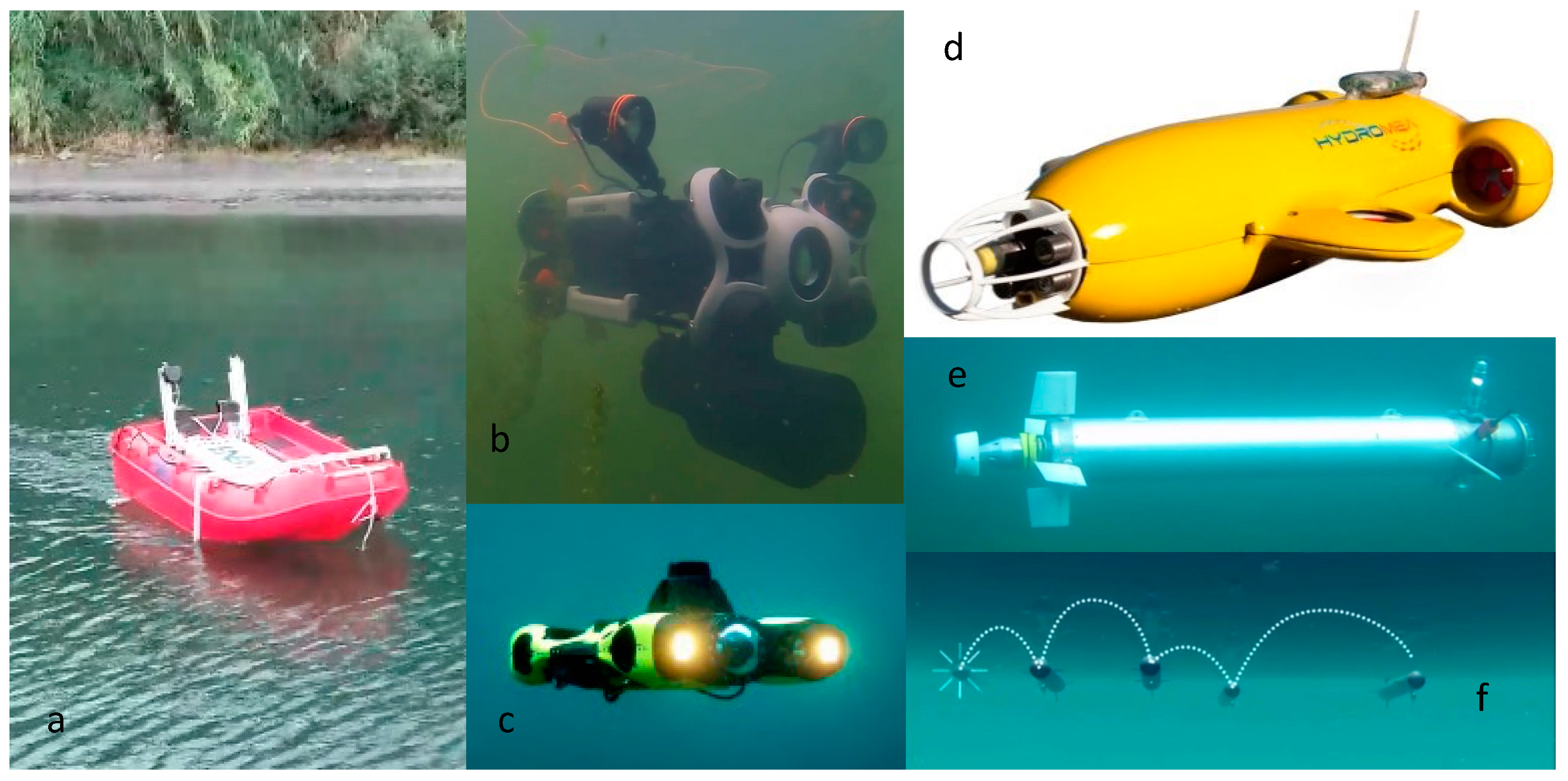
  • ASVs (autonomous surface vehicles), also called USVs (unmanned surface vehicles), are boats controlled by an autopilot, commonly linked to a ground station through at least one radio trans-receiver (for sending telemetry data) and to a radio-controller through a radio receiver module aboard the vessel, enabling manual recovery of the ASV or failsafe functions at any time. Positions, trajectories, and all on-board data acquired aboard the vessel are available on the ground station (or directly in a control room), making it possible to set waypoints of interest and let the robot follow them automatically.
  • ROVs (Remotely Operating Vehicles), due to their cost-effectiveness, excellent maneuverability and on-line acquisition capability, represent the current commercial tool for widespread use in underwater exploration. Some ROVs configurations can be equipped with an extension module, enabling the tethered cable to supply the energy required for an indefinite time due to the availability of an electrical socket on the surface.
  • AUVs (Autonomous Underwater Vehicles), unlike ROVs, are characterized by the absence of a tethering cable, relying on a battery pack for power supply and off-line data acquisition capabilities. Indefinite operation requires permanent electrical recharge/docking/recovery stations. The cost of these vehicles increases with the number of sensors fitted on-board. The more automated and powerful the vehicle, the more complex the missions it can perform.
All three systems can be broadly categorized into two groups: those still in the research stage and those that are already a market diffusion.
Regarding the research stage of ASVs, the SeaTrac autonomous boat [110] is an example of advanced technology designed for surface monitoring, equipped with various sensors to collect environmental data. Autonomous boats like the Saildrone offer extended deployment times and are used for extensive data collection, capturing observations at the air/sea interface by solar-powered meteorological and oceanographic sensors [111]. The IntCatch project is also noteworthy [112]. Although at a lower technological maturity, ENEA’s ASV shown in Figure 4 is another example of autonomous ASV prototype.
Industrialized ASVs from companies such as Liquid Robotics and ASV Global are designed for robust environmental monitoring and surface inspections. These commercial ASVs are widely utilized in marine research and environmental assessment. All ASVs, however, face challenges related to autonomy and energy management [113]. In most cases, PV modules on the vessel or wind-powered technology could resolve these issues.
On the other hand, in the first group of underwater drones, Remotely Operated Vehicles such as the OpenROV and BlueROV2 offer real-time control and data transmission, making them versatile tools for detailed inspections [114]. The main challenge with ROVs is their tethered nature, which can limit operational range and cable deployment. Commercial ROVs from manufacturers such as VideoRay and Deep Trekker offer solutions for underwater inspection and maintenance, often used in aquaculture and offshore energy sectors. These tethered systems provide a real-time video feed and can be equipped with various sensors for water quality assessment and structural inspection. A more economical way to carry out limited operations in shallow water (some limitations are, for example, depth, range, limited accuracy, optional devices available on the vehicle, etc.) should be evaluating CHASING ROV employment (Figure 4). In case the water manager needs a more flexible solution, QYSEA might be a possible choice [115]. Both solutions can be equipped with multiparametric water quality sensors and essential manipulators (e.g., gripper, mood sampler, nest, robotic arm, etc.) too, as well as possible water sampling tanks up to 500 mL. Some industrialized systems combine the benefits of both ROVs and AUVs. Saab Seaeye’s Sabertooth, for instance, can operate in both fully autonomous and remotely operated modes, offering real-time human telepresence [116].
Hydromea has also developed a hybrid ROV/AUV solution with the project named ExRay [117] (Figure 4); this project aims to drive the vehicle wirelessly with an optical channel paired with a second ROV cabled to the surface, serving as a docking station.
As far as AUVs are concerned, robots that mimic the locomotion and appearance of aquatic organisms are under development. These biomimetic robots can navigate through complex underwater structures with minimal disturbance to the environment. The SoFi (Soft Robotic Fish) developed by Katzschmann et al. in 2018 [118], for example, can swim alongside real fish (acoustically tele-guided), capturing video and environmental data with reduced invasiveness. Other prototypes characterized by different technological readiness levels, are, for example, VENUS [119] (Figure 4), UnexMin [120], and FeelHyppo [121].
Hydromea indeed is studying for an AUV solution, named VERTEX (Figure 4), with the aim to monitor the water environment with three possible types of probes on their special and compact autonomous vehicles [122]. Regarding the second category of AUVs, commercially available models include the REMUS series and those from Bluefin Robotics. These AUVs can be equipped with advanced sensors for collecting environmental data and conducting system inspections [123]. In terms of industrial products, companies such as Kongsberg and Saab offer robust AUVs designed for subsea inspection, which are commonly employed in seabed mining and the offshore energy sectors. While these systems are reliable, they come with a high cost [124]. AUVs operate without direct human control and can perform pre-programmed survey missions. For instance, Kongsberg Maritime’s HUGIN AUV series, although primarily used in the offshore sector, has the potential for adapting to monitoring tasks. These vehicles are capable of carrying multiple sensors and covering extensive areas autonomously [125]. GAVIA AUV of Teledyne Marine [126] is another example of industrial AUVs. An example of a long-range, long-duration AUV (several hundred meters) is Slocum glider, designed to be an ocean sensor platform.
Finally, although not strictly related to FPV systems, there is a fourth category of drones which deserves to be mentioned: unmanned aerial vehicles (UAVs). They could play a crucial role indeed in FPV monitoring. Advanced drone systems equipped with multispectral and thermal imaging capabilities can provide rapid, high-resolution data on panel condition and performance, for example, for PV module failure prevention. They can be rapidly deployed to investigate and detect anomalies or emergencies, providing real-time combined data, and optical and thermal imagery. The adoption of an aerial monitoring methodology for FPV suffers, however, from inherent problems arising from both the water environment (sunrise reflection and shimmering are typical problems) and the instability of the infrastructure anchorage (leading to GPS data localization error), as stated in [127].

5.2. Issues Related to Robotic Systems

5.2.1. Localization Issues

As far as surface (ASV) robot localization, GPS is generally a feasible choice, although physical obstructions and reflective surfaces from the same FPV structures can be a limitation. GPS accuracy can also be affected by atmospheric conditions, which may cause signal degradation or multipath errors. For underwater drones, the total absence of GPS signal below the water surface brings back the issue of underwater localization. So, as discussed in [70], both ROVs and AUVs need localization devices to get them geo-referenced underwater. This issue is faced using two major methods: (1) setting a short time submerged trajectory, based on the Doppler velocity technique (with Doppler Velocity Logs devices), combining INS (Inertial Navigation System), more or less expensive, and first GPS data acquired at the initial diving point and (2) long time continuous control from the surface, by an operator or a computer, through an acoustic bidirectional link. Communication links can typically be made with a mono-/bi-directional transponder anchored to the vehicle that can return the position underwater in real time to a USBL (Ultra-Short Base Line) acoustic positioning system, locating ROVs/AUVs just below the surface. These acoustic devices can be less accurate in shallow or cluttered environments (Kinsey, Eustice, and Whitcomb, 2006) [128]. Acoustic positioning systems, while effective in deep and open waters, struggle with reflections and multipath effects in confined spaces, leading to reduced accuracy. Acoustic systems are also known to be susceptible to noise and multipath effects [129]. As a consequence of the previous considerations, the main limits of these acoustic systems are the bandwidth reachable and both the range and the latency over long distances, ranging from a few hundred meters in cheaper systems to a few kilometers.

5.2.2. Data Transmission

While tethered solutions generally do not face significant challenges with data transmission, wireless and real-time monitoring in aquatic environments can encounter several obstacles. Surface robots that rely on radio and satellite communication require a clear line of sight and can be adversely affected by weather conditions. In contrast, underwater communication primarily relies on acoustic modems, which offer limited bandwidth (typically ~50 kbps) and range (typically 300 m–1 km) [130]. Acoustic communication can be disrupted by various water conditions, such as temperature gradients, salinity changes, and background noise from marine life or human activities. Such disruptions can result in data loss or delays, impacting the real-time monitoring capabilities of wireless underwater robots (e.g. AUVs) or sensors, potentially leading to missed defect detection of the FPV or an inaccurate real-time assessment of their environmental impact.
Various alternative communication channels have been investigated [131], both between drones and/or drone-to-surface buoy/infrastructure, from radio frequency (10–40 m) to optical blue/green (10–120 m) [130,132]. Underwater acoustic/optical modems, when used in a mesh network (Figure 4), can facilitate data transmission between submerged sensors, surface buoys/infrastructures, and underwater drones. These systems are equipped with dedicated and georeferenced communication systems to relay data to the cloud. On the other hand, choosing to fully automatize the submerged structure with underwater drones would mean using quite expensive localization systems. Video streaming involves even greater costs to achieve high wide communication bands to bring back a strong signal to the surface for heavy remote monitoring purposes. Hence, wireless and real-time underwater solutions are not ideal for FPV monitoring.

5.2.3. Energy Autonomy and Environmental Impact

Operational challenges include energy management and environmental impact too. Prolonged operation of robotic systems demands efficient energy use. However, energy storage and consumption remain critical concerns [113]. Battery life limits the operational time of both ASVs and ROVs/AUVs, requiring frequent recharging or battery replacement. Efficient energy management systems and the development of high-capacity, durable batteries are essential to extend operational missions. Designing docking stations for ASVs, ROVs, and AUVs is necessary to enable autonomous retrieval and docking for battery recharging, data upload, and maintenance checks, thus enabling continuous system operation. Additionally, robotic systems must minimize their environmental footprint to avoid disturbing aquatic life and prevent contamination or disruption of the water body [133]. System designs and operation should consider noise reduction, eco-friendly materials, and non-toxic lubricants to minimize environmental impact. Establishing guidelines and protocols for responsible robotic operations in aquatic environments is crucial for ensuring sustainable and ethical use. Surface and underwater drones can also carry multiparametric probes with the specific aim to monitor their own environmental footprint.

5.2.4. Operation and Maintenance

Even if FPV maintenance and operation costs are still not well assessed [127], technologies for monitoring water quality and preventing ecological problems are specifically necessary for floating solar projects [134]. As [135] reminds us, further improvements in FPV technologies are needed, in particular in the design of floating structures, instrumentation, and monitoring systems, the most important challenges concerning safety and standardization issues, such as the type of body structure.
Regarding monitoring in general, swarm robotics deserve a mention. This concept could be applied to underwater environments, allowing multiple small robots to work collaboratively. These systems could cover large areas efficiently and could provide redundancy in data collection. A swarm of robots needs an additional control layer to determine their geometric configuration. This requires robots to know each other’s distances using both acoustic and optical techniques [136,137]. Ad hoc methodologies to minimize the exchange of information between robots have been developed [138].
More generally, for operations of monitoring and maintenance performed by ASVs, ROVs, AUVs. and UAVs, a combination of them is desirable, but this is not so easy to achieve. As mentioned by [139], with the increasing complexity of underwater operation tasks, in fact, it is difficult for a single underwater drone to perform complex tasks, especially in an often-unknown underwater environment. However, more and more, AI and machine learning together enable adaptive sampling strategies, allowing robots to adjust their sampling locations and rates based on real-time data and environmental conditions. Predictive modelling could be used to anticipate potential water quality issues or failure issues, enabling the implementation of robots to better investigate the environment. Machine learning algorithms, for example, could be implemented to detect anomalies in water quality data, triggering specific autonomous investigation missions with ROVs, AUVs, or other types of drones or a combination of them.
Looking ahead, future studies should explore and develop automated data monitoring and recording systems for FPV installations in order to improve the efficiency and accessibility of data collection [135].

6. A Case Study for an FPV Autonomous Monitoring System

The environmental impact of FPV involves complex interactions between physical, chemical, and ecological components of the water body and ecosystems [71].
The monitoring system can be based on configurations made of (1) fixed sensors or (2) mobile sensors, or a hybrid configuration that combines the two.
Configuration 1 can be achieved with multiparametric probes (see Section 4) moored to floating systems (FPV or buoy) with fixed x, y, and z. Most of the literature on WQM in FPV is based on this strategy [61,69,87]. Fouling (the accumulation of microorganisms, plants, algae, or small animals on wetted surfaces) [30] has always been a problem when devices are submerged for extended periods. Modern multiparameter probes (configuration 1) have addressed this problem with different antifouling devices depending on the technology employed by the sensor. Ultraviolet light [140] prevents biofouling formation on the water conductivity cell. Optical sensors, such as dissolved oxygen and turbidimeters, can instead be kept efficient with electromechanical systems such as wipers that keep the glass clean. These antifouling devices significantly increase the energy requirements of the multiprobe, but can allow its use for longer periods of operation, even in the harshest ambient conditions [141,142,143,144]. This is the case of static positioning, with the availability of electrical energy as in the proposed monitoring system. Furthermore, they reduce sensing drift phenomena and thus contribute to maintaining accuracy requirements. Camera traps in fixed positions could be useful for registering the movements of animals, like in [145], which can also help to reduce the O&M cost burden by controlling interactions with living beings. Lundesgaard and co-authors [144] calibrate the sensors before and after deployment and, assuming linear drift, correct the final data time series. Generally, small corrections within the accuracy specified by the manufacturer are required. More effective algorithms can be implemented for non-linear drift compensation in the case of e-tongue usage. The remote management of these probes in terms of anti-vandalism, anti-theft (possibly sharing those of the FPV if present), and real-time control of the quality of the acquired data would be an added value. Machine learning algorithms could alert remote management in case of suspect data patterns (malfunctions, unexpected events, need for sensor calibration, etc.) and can be trained to recognize specific events and conditions with environmental significance. A hybrid sensor configuration can be achieved by combining configuration 1 (fixed position of the sensor in x and y) with a controlled winch to guarantee mobility of the sensors along z. A similar approach was followed by Vlaswinkel in 2023 [68] which manually controlled the winch. A further improvement to this hybrid solution can be obtained by managing the winch in a remote and automated manner. Configuration 1 and its variation would have a good degree of autonomy and a relatively low rate of human intervention.
Configuration 2 can be achieved using single carriers with the appropriate sensors integrated onboard (multiprobe, cameras, etc.); ROV and AUV can guarantee the movement of sensors in x, y, and z. Sensors to be used in motion must be calibrated following a different procedure [146]. Vehicles could be equipped with water and/or sediment sampling devices [147] to obtain biotic parameters of interest from laboratory analyses (e.g., microscopic plankton). De Lima and coauthors [69] field-tested an ROV with sensors and cameras in various pilot applications in the Netherlands. The aquatic ecology was analyzed assessing the presence of fish, aquatic plants, or other aquatic organisms, identifying fish communities, and characterizing local habitats (e.g., stock assessment). Meng and coauthors [148], through deep learning on images from a 360-degree panoramic camera, identified fish in real time. Object recognition is challenging beneath FPV because of poor lighting and backscattering caused by suspended particulates.
The analysis of the water column could be also performed with multiparametric probes moored to an ASV (which guarantees movement in x and y in open waters) combined with an automated winch (to control sensor position in z).
A more complex solution can be applied when the carrier is a team/swarm of ROVs/AUVs, also equipped with the necessary sensors and communication/self-localization capacity for team/swarm interaction. Docking systems [149] for launch, recovery, and automatic charging are necessary to reduce on-site human presence and allow remote management of the water body monitoring system. Some problems take advantage of simultaneous measurements. For example, Figure 5 shows an AUV swarm cooperating (data-driven) to efficiently map an illicit discharge outflow plume in a water body. The monitoring speed indicated by the authors (0.5 km2 in 2 h) is probably optimistic, but it is useful to have an order of magnitude of the time needed to monitor a large water body with mobile sensors.
The aim of this paragraph is to identify and highlight issues that can be encountered when studying an autonomous monitoring system for FPV installations. The study of an autonomous (with reduced human intervention) monitoring system depends heavily on the problem at hand: climatic conditions, water body types, currents, tidal effects, coverage ratios, etc. Water bodies on which an FPV system is planned to be installed (or has already been installed) can have, for example, very different dimensions. Areas can vary from 1 ha to 10,000 ha (10 km × 10 km) [56] or more, and the depths generally range from less than one meter to several tens of meters. Large areas to be monitored [21,56], very shallow water, algae bloom, etc., are issues to pay attention to for designing an autonomous monitoring system. Large areas are challenging because vehicles like ROVs, AUVs, and ASVs have limited resources in terms of navigation speed, battery life before recharge or substitution, tether length (for ROVs), etc. Furthermore, when monitoring a large area with mobile sensors in short-term analyses, survey timing could be comparable with the phases of some thermodynamic forcings such as solar radiation and wind intensity and direction. Water bodies in some cases present an algal bloom problem. A classic hub propeller may not be suitable in this situation. The design of an ROV/AUV/ASV from scratch for use in a such monitoring system could evaluate propellers such as Rim-Driven Thrusters (RDTs) [150]. Their further characterization regarding hydrodynamic performance, durability, etc., would be useful, specifically in their use with ROVs/AUVs. Commercial products exist, from large ships (Rolls-Royce, Schottel, Brunvoll, Voith, Van der Velden) to small ROV/AUV prototypes, as in [151]. Other authors used an ROV to obtain vertical profiles of water quality in FPV systems [69]. The measuring strategy of De Lima et al. was to measure and compare water quality at several depths at the center of the solar farm (beneath the FPV) and at a reference location located over 100 m away from the FPV outside its influence. The authors compared measurements acquired with static sensors (configuration 1) with measures taken with the same sensors on an ROV (configuration 2).
Figure 5. Ten AUVs cooperating (data-driven) to efficiently map illicit discharge outflow plume in a water body (0.5 km2 in 2 h) [courtesy of Hydromea SA] [152].
Sustainability 16 08367 g005

7. Discussion

The trade-offs associated with any potential FPV installation can be accurately studied through fixed and/or mobile (robotic) technologies that can measure and sample, and thus provide a comprehensive assessment of environmental and ecological impacts on water bodies. This knowledge can be used to develop reliable models and strategies to mitigate potential negative impacts of the plant, maximizing the co-benefits of FPV technology and providing synergistic benefits to the water–food–energy nexus.
Static sensors, mobile sensors, or a combination of the two different configurations can be used to design the monitoring activities of water quality under FPV plants. The selection of the best monitoring strategy depends on several factors, including the size of the FPV system and the maximum depth of the water body to be monitored. Table 3 summarizes the experiences of WQM in FPV applications analyzed in the previous paragraphs, with the aim of providing guidelines for the selection of WQM strategies in FPV applications. For each WQM experience in FPV, Table 3 includes information on the dimensions of the FPV, the maximum depth of the water body, the number and position of water columns (WCs) analyzed, the number and depths of measurement points for each water column, and the configuration of sensors adopted, whether fixed or mobile.
In terms of the dimensions of FPV, WQM of the largest FPV installation was performed by Liu and colleagues [63], who monitored several parameters (temperature, conductivity, dissolved oxygen, pH, Chl-a) in relation to an FPV implant with a total area of 400 ha, distributed across four coal mining subsidence areas. Liu and colleagues monitored two coal mining subsidence areas with multiple water columns (eight and six) under the FPV, and in open waters (three and six). All the other works performed WQM in relation to small FPV implants (<20 ha), analyzing a single water column under the FPV and a single column in open water (usually at a distance greater than 100 m from the FPV). Among the seven studies reviewed, three of them [60,61,78] included an additional water column in fringe areas, a few meters from the FPV. Hence, the literature review suggests that small installations (<20 ha) can be monitored with only two water columns: one at the center of the structure and one in open water.
Regarding the depths of water body analyzed, three studies worked with shallow waters (depth < 10 m). Yang et al. 2022 and Wang et al. 2021 monitored each WC at a single depth for each water column, at 0.8 m and 0.2 m, respectively. Liu et al. 2023 measured three depths for each water column at 0.5 m, 2 m, and 3 m. In the rest of the studies, water bodies exceeded 20 m in depth [61,68,71], and multiple depths of measurements were used with different strategies. Vlaswinkel et al. in 2023 monitored vertical profiles by slowly lowering a multiparametric probe with a manual winch (hybrid configuration), binning data at 0.5 m intervals.
The manual control of the winch obviously requires the presence of a human operator. A more autonomous solution could be achieved with a variation of this method, by managing the winch remotely and lowering the operation costs. Despite none of the reported studies using an automated winch, this is a very interesting method to perform autonomous monitoring for small FPV systems when only a reduced number of water columns is required (two or three).
A different strategy was employed by Ilgen et al., who measured vertical profiles of water temperature. In this case, several low-cost sensors were applied at a fixed location on water columns (x, y), each 0.5 m of increasing depths (z). This can be a convenient solution, when water quality monitoring is focused on a single or just a few parameters that can be measured with several cheap sensors distributed in the water body. This solution can guarantee autonomous and continuous monitoring of water quality for a long period without requiring human intervention, and with the help of mapping algorithms, it also allows 3D mapping of the monitored parameters. This approach becomes less sustainable as the number of monitored parameters increases along the vertical profile or when many water columns need to be monitored (as for large FPVs).
De Lima et al. proposed two different strategies to monitor each water column: four different sensors at fixed depths (1.5 m, 10 m, 20 m, 31.5 m) for continuous and autonomous monitoring, and a single mobile sensor equipped on-board a commercial ROV. The use of the ROV allowed the measuring of the whole vertical profile at depth steps of 1 m of two water columns with a single multiparameter probe. The advantages of this method increase when several water columns must be monitored with multiple parameters throughout the vertical profiles of a water body with a certain depth (>20 m). In this case, the cost of monitoring can be significantly reduced with the use of a robotic device equipped with an expensive multiparameter probe. As, by definition, an ROV requires human control during the monitoring activity, the solution proposed by De Lima and colleagues is not suitable when continuous WQM is required for long periods of time. A more advanced robotic solution, though more expensive, may be represented by the use of an AUV as a carrier of sensors for WQM of FPV instead of using an ROV. Despite pre-programmed missions making the use of AUVs, a more autonomous solution for WQM activities, none of the studies reviewed so far in FPV applications employed this solution. The proper use of AUVs in WQM requires advanced robotic skills, equipment, and higher costs, not justified so far for use in FPV plants. A further increase in complexity can be achieved when a team or swarm of AUVs is used. This future solution may be considered an interesting option when large water bodies need to be monitored, and vertical profiles of many water columns are required, or when a contemporary measurement of parameters at different locations is required. As the commercial offer of AUV swarms is still lacking, this solution belongs to a future scenario.

8. Conclusions

Floating PV is an emerging technology that can help the sustainable diffusion of photovoltaic energy by exploiting poorly used areas and reducing the requirement of areas more suitable for other uses, such as, for example, agricultural ones. However, even the involvement of large areas of inland or sea basins can lead to an environmental impact that has been so far poorly evaluated at an experimental level.
The extensive technical literature examined in this review highlights, however, first and foremost that there is no organic effort to monitor this impact to date, but that, on the contrary, FPV probably urgently requires the definition of general rules and criteria that photovoltaic plants should adopt both in implementation and operational management.
As regards strictly the object of this work, the literature of the sector is mainly related to photovoltaic systems built on internal basins. For these, the general recommendation is not to exceed coverage factors, equal to 50% of the available basin surface, and to monitor a series of chemical–physical parameters: submarine light intensity, Chlorophyll-a, turbidity, pH, water electric conductivity, dissolved oxygen, and temperature, both immediately below the plant and in points sufficiently away from it. There are no data related to how many of these points there should be nor how deep the column of water examined in each of them should be (and, therefore, how many samples should be examined for each column). We can obviously assume, as a starting hypothesis, that the points to be sampled are directly proportional to the extension of the FPV system, but at present, there are no specific works addressing this problem, not even from a purely modeling point of view. In any case, monitoring must be carried out both before the installation of the system and during its operational life, with a periodicity such as to be able to reliably evaluate the environmental impact of the system itself.
In addition to the standard parameters to be monitored for any photovoltaic system, floating systems require the monitoring of a series of additional parameters, which are very similar to those typical of any vessel. These parameters are in fact also essential for the study and the evaluation of the environmental impact of a floating photovoltaic system because they allow a more reliable correlation of the parameters detected with the actual state of the PV system itself. As regards the water monitoring technologies most suitable for this purpose, the review highlights the need for ad hoc solutions that can positively exploit the existing compromise between the cost of the detection units, their number, and the profiles and the width of the area to be monitored. The choice is between solutions based on multiparametric probes managed by specialized personnel and means, or through completely mobile systems or even autonomous units such as ASV/AUV solutions. Again, there are not enough data to make a choice. However, while the first solution certainly involves a broader and more complex use of specialized personnel, the second minimizes human intervention, and could also more easily adapt, in theory, to operational contexts, such as, for example, off-shore ones, where the use of unmanned solutions is also preferable for security reasons. For robotic agents, various technical solutions underlying innovative sampling technologies were therefore reviewed with the aim of presenting their strengths and weaknesses in different operational scenarios.
This review paper highlights the need for a standardized approach to water quality management (WQM) in relation to floating photovoltaic (FPV) systems. Moving forward, future research should prioritize water quality modeling to thoroughly assess the potential impacts of FPV systems on water ecosystems, taking into account various water body types (e.g., lakes, reservoirs, estuarine and coastal areas, hydropower reservoirs) and linking their specific properties (e.g., depth, size) with the characteristics of FPV plants (e.g., coverage ratio). A multidisciplinary approach, drawing on expertise from physicists, ecologists, pedologists, and other specialists, will be essential for the effective development, calibration, and validation of these models [153,154]. Several advanced hydrodynamic and water quality modeling tools, such as ELCOM-CAEDYM, MIKE, and Delft3D, offer promising solutions for this task [21,56]. By utilizing these tools, we can work toward a standardized WQM framework that incorporates the interactions between water bodies and FPV systems. Ultimately, these efforts should culminate in the development of comprehensive guidelines that will inform the selection of critical parameters to monitor, alongside their optimal spatial and temporal distribution. This approach will significantly enhance our ability to manage and mitigate the environmental impacts of FPV installations, paving the way for more sustainable integration of renewable energy technologies.

Author Contributions

Conceptualization: G.D.F. and G.M.T.; methodology: G.D.F., G.M.T., M.S., S.B., L.B., G.C., S.D.V. and A.C.; formal analysis: S.B., L.B., G.C., R.d., S.D.V. and A.C.; writing—original draft preparation: G.D.F., G.M.T., S.B, G.C., L.B. and S.D.V.; writing—review and editing: S.B., G.D.F.; visualization: S.B. and G.D.F.; supervision: G.D.F. and G.M.T.; funding acquisition: G.D.F. and G.M.T. All authors have read and agreed to the published version of the manuscript.

Funding

This research received funding partly from Ministero per lo Sviluppo Economico, Fondo per la Crescita Sostenibile, under the framework “Accordi per l’innovazione di cui al D.M. 31 Dicembre 2021 e DD 18 Marzo 2022”, project MARTA, n.: F/310193/01-02/X56 and partly from PRIN 2020 “A Holistic Monitoring and Diagnostic Tool for Photovoltaic Generators (HOTSPHOT)” project (CUP:E63C2001116000).

Institutional Review Board Statement

Not applicable.

Informed Consent Statement

Not applicable.

Data Availability Statement

Not applicable.

Conflicts of Interest

The authors declare no conflict of interest.

References

  1. Nijsse, F.J.M.M.; Mercure, J.F.; Ameli, N.; Larosa, F.; Kothari, S.; Rickman, J.; Vercoulen, P.; Pollitt, H. The momentum of the solar energy transition. Nat. Commun. 2023, 14, 6542. [Google Scholar] [CrossRef] [PubMed]
  2. Nøland, J.K.; Auxepaules, J.; Rousset, A.; Perney, B.; Falletti, G. Spatial energy density of large-scale electricity generation from power sources worldwide. Sci. Rep. 2022, 12, 21280. [Google Scholar] [CrossRef] [PubMed]
  3. Bolinger, M.; Bolinger, G. Land Requirements for Utility-Scale PV: An Empirical Update on Power and Energy Density. IEEE J. Photovolt. 2022, 12, 589–594. [Google Scholar] [CrossRef]
  4. Capellán-Pérez, I.; Castro, C.; Arto, I. Assessing vulnerabilities and limits in the transition to renewable energies: Land requirements under 100% solar energy scenarios. Renew. Sustain. Energy Rev. 2017, 77, 760–782. [Google Scholar] [CrossRef]
  5. Sargentis, G.-F.; Siamparina, P.; Sakki, G.-K.; Efstratiadis, A.; Chiotinis, M.; Koutsoyiannis, D. Agricultural Land or Photovoltaic Parks? The Water–Energy–Food Nexus and Land Development Perspectives in the Thessaly Plain, Greece. Sustainability 2021, 13, 8935. [Google Scholar] [CrossRef]
  6. Cagle, A.E.; Armstrong, A.; Exley, G.; Grodsky, S.M.; Macknick, J.; Sherwin, J.; Hernandez, R.R. The Land Sparing, Water Surface Use Efficiency, and Water Surface Transformation of Floating Photovoltaic Solar Energy Installations. Sustainability 2020, 12, 8154. [Google Scholar] [CrossRef]
  7. Floating PV on a Quarry Lake in Southern Germany. Available online: https://www.pv-magazine.com/2020/11/16/floating-pv-on-a-quarry-lake-in-southern-germany/ (accessed on 19 September 2024).
  8. Trapani, K.; Redõn Santafé, M. A review of floating photovoltaic installations: 2007–2013. Prog. Photovolt. Res. Appl. 2015, 23, 524–532. [Google Scholar] [CrossRef]
  9. Amiot, B.; Le Berre, R.; Giroux-Julien, S. Evaluation of thermal boundary conditions in floating photovoltaic systems. Prog. Photovolt. Res. Appl. 2023, 31, 251–268. [Google Scholar] [CrossRef]
  10. Bontempo Scavo, F.; Tina, G.M.; Gagliano, A.; Nižetić, S. An assessment study of evaporation rate models on a water basin with floating photovoltaic plants. Int. J. Energy Res. 2021, 45, 167–188. [Google Scholar] [CrossRef]
  11. Prefab Floating Solar for Easy Installation. Available online: https://www.pv-magazine.com/2022/06/28/prefab-floating-solar-for-easy-installation/ (accessed on 19 September 2024).
  12. Rosa-Clot, M. (Pisa, Italy). Private communication. 2024. [Google Scholar]
  13. Hernández-Callejo, L.; Gallardo-Saavedra, S.; Alonso-Gómez, V. A Review of Photovoltaic Systems: Design, Operation and Maintenance. Sol. Energy 2019, 188, 426–440. [Google Scholar] [CrossRef]
  14. Chen, X.; Zhou, W. Performance Evaluation of Aquavoltaics in China: Retrospect and Prospect. Renew. Sustain. Energy Rev. 2023, 173, 113109. [Google Scholar] [CrossRef]
  15. Hu, J.; Teng, K.; Li, C.; Li, X.; Wang, J.; Lund, P.D. Review of Recent Water Photovoltaics Development. Oxf. Open Energy 2023, 2, oiad005. [Google Scholar] [CrossRef]
  16. Cazzaniga, R.; Cicu, M.; Rosa-Clot, M.; Rosa-Clot, P.; Tina, G.M.; Ventura, C. Floating Photovoltaic Plants: Performance Analysis and Design Solutions. Renew. Sustain. Energy Rev. 2018, 81, 1730–1741. [Google Scholar] [CrossRef]
  17. Rosa-Clot, M.; Marco Tina, G. Chapter 7—Tracking Systems. In Floating PV Plants; Rosa-Clot, M., Marco Tina, G., Eds.; Academic Press: Cambridge, MA, USA, 2020; pp. 79–87. [Google Scholar] [CrossRef]
  18. Shi, W.; Yan, C.; Ren, Z.; Yuan, Z.; Liu, Y.; Zheng, S.; Li, X.; Han, X. Review on the Development of Marine Floating Photovoltaic Systems. Ocean Eng. 2023, 286, 115560. [Google Scholar] [CrossRef]
  19. Wu, S.; Jiang, N.; Zhang, S.; Zhang, P.; Zhao, P.; Liu, Y.; Wang, Y. Discussion on the Development of Offshore Floating Photovoltaic Plants, Emphasizing Marine Environmental Protection. Front. Mar. Sci. 2024, 11, 1336783. [Google Scholar] [CrossRef]
  20. Claus, R.; López, M. Key Issues in the Design of Floating Photovoltaic Structures for the Marine Environment. Renew. Sustain. Energy Rev. 2022, 164, 112502. [Google Scholar] [CrossRef]
  21. World Bank Group; ESMAP; SERIS. Where Sun Meets Water: Floating Solar Market Report; World Bank: Washington, DC, USA, 2019. Available online: http://documents.worldbank.org/curated/en/670101560451219695/Floating-Solar-Market-Report (accessed on 19 September 2024).
  22. Sobolewski, K.; Sobieska, E. Lightning Protection of Floating Photovoltaic Power Plants—Simulation Analysis of Sample Solutions. Energies 2023, 16, 4222. [Google Scholar] [CrossRef]
  23. Ghosh, A. A Comprehensive Review of Water Based PV: Flotavoltaics, under Water, Offshore & Canal Top. Ocean Eng. 2023, 281, 115044. [Google Scholar] [CrossRef]
  24. Gorjian, S.; Sharon, H.; Ebadi, H.; Kant, K.; Scavo, F.B.; Tina, G.M. Recent Technical Advancements, Economics and Environmental Impacts of Floating Photovoltaic Solar Energy Conversion Systems. J. Clean. Prod. 2021, 278, 124285. [Google Scholar] [CrossRef]
  25. Acharya, M.; Devraj, S. Floating Solar Photovoltaic (FSPV): A Third Pillar to Solar PV Sector? TERI Discussion Paper; Output of the ETC India Project (The Energy and Resources Institute): New Delhi, India, 2019. [Google Scholar]
  26. Mayville, P.; Patil, N.V.; Pearce, J.M. Distributed Manufacturing of after Market Flexible Floating Photovoltaic Modules. Sustain. Energy Technol. Assess. 2020, 42, 100830. [Google Scholar] [CrossRef]
  27. Trapani, K.; Millar, D.L. The Thin Film Flexible Floating PV (T3F-PV) Array: The Concept and Development of the Prototype. Renew. Energy 2014, 71, 43–50. [Google Scholar] [CrossRef]
  28. Kanotra, R.; Shankar, R. Floating Solar Photovoltaic Mooring System Design and Analysis. In Proceedings of the OCEANS 2022—Chennai, Chennai, India, 21–24 February 2022; pp. 1–9. [Google Scholar] [CrossRef]
  29. Rosa-Clot, M.; Tina, G.M. Submerged and Floating Photovoltaic Systems. Rosa-Clot, M., Tina, G.M., Eds.; Academic Press: Cambridge, MA, USA, 2018; Chapter 8; pp. 185–212. [Google Scholar] [CrossRef]
  30. DNV. Design, Development and Operation of Floating Solar Photovoltaic Systems. DNV-RP-0584, March 2021; amended October 2021. Available online: https://brandcentral.dnv.com/fr/gallery/10651/others/0338546af264473e8481ba6ea78daf0f_hi.pdf (accessed on 19 September 2024).
  31. Alcañiz, A.; Monaco, N.; Isabella, O.; Ziar, H. Offshore Floating PV–DC and AC Yield Analysis Considering Wave Effects. Energy Convers. Manag. 2024, 300, 117897. [Google Scholar] [CrossRef]
  32. Bugeja, R.; Mule’ Stagno, L.; Dexarcis, L. An Offshore Solar Irradiance Calculator (OSIC) Applied to Photovoltaic Tracking Systems. Energies 2023, 16, 3735. [Google Scholar] [CrossRef]
  33. Nurhakim, A.; Effendi, M.R.; Saputra, H.M.; Mardiati, R.; Priatna, T.; Ismail, N. A Novel Approach to Calculating Yaw Angles Using an Accelerometer Sensor. In Proceedings of the 2019 IEEE 5th International Conference on Wireless and Telematics (ICWT), Yogyakarta, Indonesia, 25–26 July 2019; pp. 1–4. [Google Scholar] [CrossRef]
  34. Delacroix, S.; Bourdier, S.; Soulard, T.; Elzaabalawy, H.; Vasilenko, P. Experimental Modelling of a Floating Solar Power Plant Array under Wave Forcing. Energies 2023, 16, 5198. [Google Scholar] [CrossRef]
  35. Rossi, G.B.; Cannata, A.; Iengo, A.; Migliaccio, M.; Nardone, G.; Piscopo, V.; Zambianchi, E. Measurement of Sea Waves. Sensors 2021, 22, 78. [Google Scholar] [CrossRef]
  36. Choi, Y.-K.; Lee, N.-H.; Lee, A.-K.; Kim, K.-J. A Study on Major Design Elements of Tracking-Type Floating Photovoltaic Systems. SGCE 2014, 3, 70–74. [Google Scholar] [CrossRef]
  37. Micheli, L. The Temperature of Floating Photovoltaics: Case Studies, Models and Recent Findings. Sol. Energy 2022, 242, 234–245. [Google Scholar] [CrossRef]
  38. Santos, L.D.O.; De Carvalho, P.C.M.; Filho, C.D.O.C. Photovoltaic Cell Operating Temperature Models: A Review of Correlations and Parameters. IEEE J. Photovolt. 2022, 12, 179–190. [Google Scholar] [CrossRef]
  39. Peters, I.M.; Nobre, A.M. Deciphering the Thermal Behavior of Floating Photovoltaic Installations. Sol. Energy Adv. 2022, 2, 100007. [Google Scholar] [CrossRef]
  40. Tina, G.M.; Bontempo Scavo, F.; Merlo, L.; Bizzarri, F. Analysis of Water Environment on the Performances of Floating Photovoltaic Plants. Renew. Energy 2021, 175, 281–295. [Google Scholar] [CrossRef]
  41. Lindholm, D.; Selj, J.; Kjeldstad, T.; Fjær, H.; Nysted, V. CFD Modelling to Derive U-Values for Floating PV Technologies with Large Water Footprint. Sol. Energy 2022, 238, 238–247. [Google Scholar] [CrossRef]
  42. Hamdi, R.T.A.; Hafad, S.A.; Kazem, H.A.; Chaichan, M.T. Humidity Impact on Photovoltaic Cells Performance: A Review. Int. J. Recent Eng. Res. Dev. 2018, 3, 27–37. [Google Scholar]
  43. Luo, W.; Isukapalli, S.N.; Vinayagam, L.; Ting, S.A.; Pravettoni, M.; Reindl, T.; Kumar, A. Performance Loss Rates of Floating Photovoltaic Installations in the Tropics. Sol. Energy 2021, 219, 58–64. [Google Scholar] [CrossRef]
  44. Shaju, A.; Chacko, R. Soiling of Photovoltaic Modules—Review. IOP Conf. Ser. Mater. Sci. Eng. 2018, 396, 012050. [Google Scholar] [CrossRef]
  45. Francia, D.F.; De Vito, S.; Fattoruso, G.; Matano, A. Energy transition: An analysis of agrivoltaic utilities suitability in terms of Levelized Cost of Electric Energy. In Proceedings of the Global Energy Transition Toward Decarbonization: A Multi-Scalar Perspective and Transformation, Milan, Italy, 24–27 July 2023. [Google Scholar]
  46. Willers, G.; Naumann, V.; Holzlohner, R.; Gottschalg, R.; Ilse, K. Analysis of Threshold Conditions for Cementation of Soiling on PV Modules and Telescope Mirrors. IEEE J. Photovolt. 2024, 14, 330–336. [Google Scholar] [CrossRef]
  47. Dewi, T.; Taqwa, A.; Rusdianasari; Kusumanto, R.D.; Sitompul, C.R. The Investigation of Sea Salt Soiling on PV Panel. In Proceedings of the 4th Forum in Research, Science, and Technology (FIRST-T1-T2-2020), Palembang, Indonesia, 10-11 November 2020; Atlantis Press: Amsterdam, The Netherlands, 2021; pp. 141–147. [Google Scholar] [CrossRef]
  48. Boeing, A.; Neda, M.; Steinberg, S.; Batista, J. The Impact of Lower Quality Water on Soiling Removal from Photovoltaic Panels. Renew. Sustain. Energy Rev. 2022, 169, 112870. [Google Scholar] [CrossRef]
  49. Nordin, M.; Sharma, S.; Khan, A.; Gianni, M.; Rajendran, S.; Sutton, R. Collaborative Unmanned Vehicles for Inspection, Maintenance, and Repairs of Offshore Wind Turbines. Drones 2022, 6, 137. [Google Scholar] [CrossRef]
  50. NPR. Solar Energy Project Location Debate. NPR [Internet]. 18 June 2023. Available online: https://www.npr.org/2023/06/18/1177524841/solar-energy-project-location-debate (accessed on 10 July 2024).
  51. Mirletz, H.; Hieslmair, H.; Ovaitt, S.; Curtis, T.L.; Barnes, T.M. Unfounded Concerns about Photovoltaic Module Toxicity and Waste Are Slowing Decarbonization. Nat. Phys. 2023, 19, 1376–1378. [Google Scholar] [CrossRef]
  52. Gunerhan, H.; Hepbasli, A.; Giresunlu, U. Environmental Impacts from the Solar Energy Systems. Energy Sources Part A Recovery Util. Environ. Eff. 2008, 31, 131–138. [Google Scholar] [CrossRef]
  53. Exley, G.; Page, T.; Thackeray, S.J.; Folkard, A.M.; Couture, R.-M.; Hernandez, R.R.; Cagle, A.E.; Salk, K.R.; Clous, L.; Whittaker, P.; et al. Floating Solar Panels on Reservoirs Impact Phytoplankton Populations: A Modelling Experiment. J. Environ. Manag. 2022, 324, 116410. [Google Scholar] [CrossRef]
  54. Exley, G.; Hernandez, R.R.; Page, T.; Chipps, M.; Gambro, S.; Hersey, M.; Lake, R.; Zoannou, K.-S.; Armstrong, A. Scientific and Stakeholder Evidence-Based Assessment: Ecosystem Response to Floating Solar Photovoltaics and Implications for Sustainability. Renew. Sustain. Energy Rev. 2021, 152, 111639. [Google Scholar] [CrossRef]
  55. Haas, J.; Khalighi, J.; De La Fuente, A.; Gerbersdorf, S.U.; Nowak, W.; Chen, P.-J. Floating Photovoltaic Plants: Ecological Impacts versus Hydropower Operation Flexibility. Energy Convers. Manag. 2020, 206, 112414. [Google Scholar] [CrossRef]
  56. Stichting Toegepast Onderzoek Waterbeheer. Zonneparken Versie Maart 2019; STOWA: Amersfoort, The Netherlands, 2019; Available online: https://www.stowa.nl/sites/default/files/assets/PUBLICATIES/Publicaties%202018/STOWA%202018-73%20Zonneparken%20versie%20maart%202019.pdf (accessed on 19 September 2024).
  57. Ribeiro, H.V.; Acre, M.R.; Faulkner, J.D.; Da Cunha, L.R.; Lawson, K.M.; Wamboldt, J.J.; Brey, M.K.; Woodley, C.M.; Calfee, R.D. Effects of Shady Environments on Fish Collective Behavior. Sci. Rep. 2022, 12, 17873. [Google Scholar] [CrossRef] [PubMed]
  58. Misman, N.A.; Sharif, M.F.; Chowdhury, A.J.K.; Azizan, N.H. Water Pollution and the Assessment of Water Quality Parameters: A Review. Desalin. Water Treat. 2023, 294, 79–88. [Google Scholar] [CrossRef]
  59. Yang, P.; Chua, L.H.C.; Irvine, K.N.; Nguyen, M.T.; Low, E.-W. Impacts of a Floating Photovoltaic System on Temperature and Water Quality in a Shallow Tropical Reservoir. Limnology 2022, 23, 441–454. [Google Scholar] [CrossRef]
  60. Al-Widyan, M.; Khasawneh, M.; Abu-Dalo, M. Potential of Floating Photovoltaic Technology and Their Effects on Energy Output, Water Quality and Supply in Jordan. Energies 2021, 14, 8417. [Google Scholar] [CrossRef]
  61. Ilgen, K.; Schindler, D.; Wieland, S.; Lange, J. The Impact of Floating Photovoltaic Power Plants on Lake Water Temperature and Stratification. Sci. Rep. 2023, 13, 7932. [Google Scholar] [CrossRef]
  62. Bai, Q.; Li, R.; Li, Z.; Leppäranta, M.; Arvola, L.; Li, M. Time-Series Analyses of Water Temperature and Dissolved Oxygen Concentration in Lake Valkea-Kotinen (Finland) during Ice Season. Ecol. Inform. 2016, 36, 181–189. [Google Scholar] [CrossRef]
  63. Liu, Z.; Ma, C.; Li, X.; Deng, Z.; Tian, Z. Aquatic Environment Impacts of Floating Photovoltaic and Implications for Climate Change Challenges. J. Environ. Manag. 2023, 346, 118851. [Google Scholar] [CrossRef]
  64. Wang, T.; Chang, P.; Huang, Y.; Lin, T.; Yang, S.; Yeh, S.; Tung, C.; Kuo, S.; Lai, H.; Chen, C. Effects of Floating Photovoltaic Systems on Water Quality of Aquaculture Ponds. Aquac. Res. 2022, 53, 1304–1315. [Google Scholar] [CrossRef]
  65. Bhattacharya, M.; Kumar, A.; Nema, A.K.; Das, S.; Vijayanandan, A. Making a Case for Environmental Risk-Based Monitoring of Floating Solar Systems. Environ. Sci. Technol. 2024, 58, 2595–2597. [Google Scholar] [CrossRef]
  66. Atikah, R.H.; Wahyuningsih, N.P.S.; Suwartha, N.; Setiawan, E.A. Spatial Analysis of Water Quality Parameters Concentration around the Floating Solar Panel Installation in Lake Mahoni, Depok, Indonesia. E3S Web Conf. 2024, 485, 01010. [Google Scholar] [CrossRef]
  67. Song, F.; Lu, Z.; Guo, Z.; Wang, Y.; Ma, L. The Effects of a Fishery Complementary Photovoltaic Power Plant on the Near-Surface Meteorology and Water Quality of Coastal Aquaculture Ponds. Water 2024, 16, 526. [Google Scholar] [CrossRef]
  68. Vlaswinkel, B.; Roos, P.; Nelissen, M. Environmental Observations at the First Offshore Solar Farm in the North Sea. Sustainability 2023, 15, 6533. [Google Scholar] [CrossRef]
  69. De Lima, R.L.P.; Paxinou, K.; Boogaard, F.C.; Akkerman, O.; Lin, F.-Y. In-Situ Water Quality Observations under a Large-Scale Floating Solar Farm Using Sensors and Underwater Drones. Sustainability 2021, 13, 6421. [Google Scholar] [CrossRef]
  70. Ubina, N.A.; Cheng, S.-C. A Review of Unmanned System Technologies with Its Application to Aquaculture Farm Monitoring and Management. Drones 2022, 6, 12. [Google Scholar] [CrossRef]
  71. De Lima, R.L.P.; De Graaf-van Dinther, R.E.; Boogaard, F.C. Impacts of Floating Urbanization on Water Quality and Aquatic Ecosystems: A Study Based on In Situ Data and Observations. J. Water Clim. Chang. 2022, 13, 1185–1203. [Google Scholar] [CrossRef]
  72. Chatziantoniou, A.; Papandroulakis, N.; Stavrakidis-Zachou, O.; Spondylidis, S.; Taskaris, S.; Topouzelis, K. Aquasafe: A Remote Sensing, Web-Based Platform for the Support of Precision Fish Farming. Appl. Sci. 2023, 13, 6122. [Google Scholar] [CrossRef]
  73. Bao, H.; Zhang, Y.; Song, M.; Kong, Q.; Hu, X.; An, X. A Review of Underwater Vehicle Motion Stability. Ocean Eng. 2023, 287, 115735. [Google Scholar] [CrossRef]
  74. YSI Inc. YSI EXO Multiparameter Water Quality Sondes. Available online: https://www.ysi.com/file%20library/documents/brochures%20and%20catalogs/ysi-exo-brochure.pdf (accessed on 19 September 2024).
  75. YSI Inc. YSI 6920 V2-2 Multiparameter Water Quality Sondes. Available online: https://www.ysi.com/6920-v2-2 (accessed on 19 September 2024).
  76. Quadlink Tech. Aquadlink® Smart Aquaculture Application System. Available online: https://www.quadlink-tech.com/en/a4-11108-14327/Aquadlink%C2%AESmart-Aquaculture-Application-System.html (accessed on 19 September 2024).
  77. Myron L. Ultrapen PT1; Myron L: Carlsbad, CA, USA, 2024. Available online: https://www.myronl.com/products/handheld-portable-instruments/ultrapen-pt1/?gad_source=1&gclid=Cj0KCQjw7ZO0BhDYARIsAFttkCjR7sQRJ3sgPw4j1wK9lzwPxDoptNmhcrqKIY5AyNtjv1LHsXB82KQaAijJEALw_wcB (accessed on 4 July 2024).
  78. De Lima, R.L.P.; Boogaard, F.C.; De Graaf-van Dinther, R.E. Innovative Water Quality and Ecology Monitoring Using Underwater Unmanned Vehicles: Field Applications, Challenges and Feedback from Water Managers. Water 2020, 12, 1196. [Google Scholar] [CrossRef]
  79. In-Situ Inc. TROLL® 9500 Multiparameter Water Quality Monitoring Instrument. Available online: https://www.inmtn.com/docs/IEI_Troll9500_bro.pdf (accessed on 19 September 2024).
  80. Van Essen Instruments. CTD Diver—Downloads; Van Essen Instruments: Delft, The Netherlands, 2024; Available online: https://www.vanessen.com/products/data-loggers/ctd-diver/#tab-downloads (accessed on 4 July 2024).
  81. AQUAREAD. AP-2000/2000-D Advanced Multiparameter Water Quality Probes. Available online: https://www.aquaread.com/products/water-quality/ap-2000 (accessed on 19 September 2024).
  82. PME. PME miniDOT Dissolved Oxygen Logger Specifications. Fondriest Environmental. Available online: https://www.fondriest.com/pme-minidot-dissolved-oxygen-logger.htm (accessed on 4 July 2024).
  83. Germ, M.; Tertinek, Ž.; Zelnik, I. Diversity of Macrophytes and Macroinvertebrates in Different Types of Standing Waters in the Drava Field. Water 2024, 16, 1130. [Google Scholar] [CrossRef]
  84. Aquaread. AP-7000; Aquaread: Broadstairs, UK, 2020; Available online: https://www.aquaread.com/products/water-quality/ap-7000 (accessed on 4 July 2024).
  85. Krohkaew, J.; Nilaphruek, P.; Witthayawiroj, N.; Uapipatanakul, S.; Thwe, Y.; Crisnapati, P.N. Thailand Raw Water Quality Dataset Analysis and Evaluation. Data 2023, 8, 141. [Google Scholar] [CrossRef]
  86. Eureka Water Probes. Sonde Multiparametriche per Operatori di Campo. Manta+. Available online: https://www.waterprobes.com/product-page/manta-35 (accessed on 19 September 2024).
  87. Liu, X.; Georgakakos, A.P. Chlorophyll a Estimation in Lakes Using Multi-Parameter Sonde Data. Water Res. 2021, 205, 117661. [Google Scholar] [CrossRef]
  88. Nazirova, K.; Alferyeva, Y.; Lavrova, O.; Shur, Y.; Soloviev, D.; Bocharova, T.; Strochkov, A. Comparison of In Situ and Remote-Sensing Methods to Determine Turbidity and Concentration of Suspended Matter in the Estuary Zone of the Mzymta River, Black Sea. Remote Sens. 2021, 13, 143. [Google Scholar] [CrossRef]
  89. RBR Global. RBRduo3 & RBRconcerto3|C.T, C.T.D, C.T.D++; RBR Global: Ottawa, ON, Canada, 2024; Available online: https://rbr-global.com/products/standard-loggers (accessed on 4 July 2024).
  90. Salas-Cueva, N.F.; Mendoza, J.; Cutipa-Luque, J.C.; Yanyachi, P.R. An Open-Source Wireless Platform for Real-Time Water Quality Monitoring with Precise Global Positioning. Int. J. Adv. Comput. Sci. Appl. 2021, 12, 775–782. [Google Scholar] [CrossRef]
  91. In-Situ. Aqua TROLL 500-600-700-800 Spec Sheet. Available online: https://in-situ.com/pub/media/support/documents/Aqua-TROLL-500-600-700-800_Spec-Sheet_ltr_en.pdf (accessed on 4 July 2024).
  92. Boehrer, B.; Saiki, K.; Ohba, T.; Tanyileke, G.; Rouwet, D.; Kusakabe, M. Carbon Dioxide in Lake Nyos, Cameroon, Estimated Quantitatively from Sound Speed Measurements. Front. Earth Sci. 2021, 9, 645011. [Google Scholar] [CrossRef]
  93. Idronaut. IDRONAUT OCEAN SEVEN 316Plus CTD for Oceanography; Idronaut: Brugherio, Italy, 2023; Available online: www.idronaut.it/wp-content/uploads/2021/10/oceanseven316plus-leaflet.pdf (accessed on 4 July 2024).
  94. Marsili-Libelli, S. Fuzzy Prediction of the Algal Blooms in the Orbetello Lagoon. Environ. Model. Softw. 2004, 19, 799–808. [Google Scholar] [CrossRef]
  95. Di Natale, C.; Davide, F.; D’Amico, A.; Legin, A.; Rudinitskaya, A.; Selezenev, B.; Vlasov, Y. Technical Digest of Eurosensors X; Eurosensors Association: Leuven, Belgium, 1996; pp. 1345–1348. [Google Scholar]
  96. Yu, V.; Legin, A.; Rudnitskaya, A.; Di Natale, C.; D’Amico, A. Nonspecific Sensor Arrays (“Electronic Tongue”) for Chemical Analysis of Liquids. Pure Appl. Chem 2005, 77, 1965–1983. [Google Scholar]
  97. Tønning, E.; Sapelnikova, S.; Christensen, J.; Carlsson, C.; Winther-Nielsen, M.; Dock, E.; Solna, R.; Skladal, P.; Nørgaard, L.; Ruzgas, T.; et al. Chemometric Exploration of an Amperometric Biosensor Array for Fast Determination of Wastewater Quality. Biosens. Bioelectron. 2005, 21, 608–617. [Google Scholar] [CrossRef]
  98. Gabrieli, G.; Muszynski, M.; Ruch, P.W. Feature Importance Methods Unveiling the Cross-Sensitive Response of an Integrated Sensor Array to Quantify Major Cations in Drinking Water. In Proceedings of the 2022 IEEE Sensors, Dallas, TX, USA, 30 October 2022–2 November 2022; pp. 1–4. [Google Scholar] [CrossRef]
  99. Martınez-Máñez, R.; Soto, J.; Garcia-Breijo, E.; Gil, L.; Ibáñez, J.; Llobet, E. An “Electronic Tongue” Design for the Qualitative Analysis of Natural Waters. Sens. Actuators B Chem. 2005, 104, 302–307. [Google Scholar] [CrossRef]
  100. Mimendia, A.; Gutiérrez, J.M.; Leija, L.; Hernández, P.R.; Favari, L.; Muñoz, R.; Del Valle, M. A Review of the Use of the Potentiometric Electronic Tongue in the Monitoring of Environmental Systems. Environ. Model. Softw. 2010, 25, 1023–1030. [Google Scholar] [CrossRef]
  101. Cetó, X.; Valle, M.D. Electronic Tongue Applications for Wastewater and Soil Analysis. iScience 2022, 25, 104304. [Google Scholar] [CrossRef]
  102. Campos, I.; Alcañiz, M.; Aguado, D.; Barat, R.; Ferrer, J.; Gil, L.; Marrakchi, M.; Martínez-Mañez, R.; Soto, J.; Vivancos, J.L. A voltammetric electronic tongue as tool for water quality monitoring in wastewater treatment plants. Water Res. 2012, 46, 2605–2614. [Google Scholar] [CrossRef]
  103. Cruz, M.G.N.; Ferreira, N.S.; Gomes, M.T.S.R.; Botelho, M.J.; Costa, S.T.; Vale, C.; Rudnitskaya, A. Determination of Paralytic Shellfish Toxins Using Potentiometric Electronic Tongue. Sens. Actuators B Chem. 2018, 263, 550–556. [Google Scholar] [CrossRef]
  104. Ruch, P.W.; Hu, R.; Capua, L.; Temiz, Y.; Paredes, S.; Lopez, A.; Barroso, J.; Cox, A.; Nakamura, E.; Matsumoto, K. A Portable Potentiometric Electronic Tongue Leveraging Smartphone and Cloud Platforms. In Proceedings of the 2019 IEEE International Symposium on Olfaction and Electronic Nose (ISOEN), Fukuoka, Japan, 26–29 May 2019; pp. 1–3. [Google Scholar] [CrossRef]
  105. Arzamendia, M.; Britez, D.; Recalde, G.; Gomez, V.; Santacruz, M.; Gregor, D.; Gutierrez, D.; Toral, S.; Cuellar, F. An Autonomous Surface Vehicle for Water Quality Measurements in a Lake Using MQTT Protocol. In Proceedings of the 2021 IEEE CHILEAN Conference on Electrical, Electronics Engineering, Information and Communication Technologies (CHILECON), Valparaíso, Chile, 6–9 December 2021; pp. 1–5. [Google Scholar] [CrossRef]
  106. Beshah, W.T.; Moorhead, J.; Dash, P.; Moorhead, R.J.; Herman, J.; Sankar, M.S.; Chesser, D.; Lowe, W.; Simmerman, J.; Turnage, G. IoT Based Real-Time Water Quality Monitoring and Visualization System Using an Autonomous Surface Vehicle. In Proceedings of the OCEANS 2021: San Diego—Porto, San Diego, CA, USA, 20–23 September 2021; pp. 1–4. [Google Scholar] [CrossRef]
  107. Kaushal, P.; Mudhalwadkar, R.P. Internet of Things Enabled Electronic Tongue for Remote Monitoring of Water Quality. In Smart Sensors Measurements and Instrumentation; Santhosh, K.V., Guruprasad, R.K., Eds.; Springer: Singapore, 2021; pp. 71–79. [Google Scholar]
  108. Mayflower: World’s Cleverest Robotic Ship Gets Ready to Cross and Study the Atlantic. Available online: https://research.ibm.com/blog/mayflower-to-cross-the-atlantic (accessed on 11 July 2024).
  109. Rudnitskaya, A. Calibration Update and Drift Correction for Electronic Noses and Tongues. Front. Chem. 2018, 6, 433. [Google Scholar] [CrossRef]
  110. Simmerman, J.; Chesser, G.D.; Lowe, J.W.; Moorhead, J.; Beshah, W.; Turnage, G.; Dash, P.; Sankar, M.S.; Moorhead, R.; Herman, J. Evaluation of the Utility and Performance of an Autonomous Surface Vehicle for Mobile Monitoring of Waterborne Biochemical Agents. In Proceedings of the OCEANS 2021: San Diego—Porto, San Diego, CA, USA, 20–23 September 2021; pp. 1–10. [Google Scholar] [CrossRef]
  111. Gentemann, C.L.; Scott, J.P.; Mazzini, P.L.F.; Pianca, C.; Akella, S.; Minnett, P.J.; Cornillon, P.; Fox-Kemper, B.; Cetinić, I.; Chin, T.M.; et al. Saildrone: Adaptively Sampling the Marine Environment. Bull. Am. Meteorol. Soc. 2020, 101, E744–E762. [Google Scholar] [CrossRef]
  112. Steccanella, L.; Bloisi, D.D.; Castellini, A.; Farinelli, A. Waterline and Obstacle Detection in Images from Low-Cost Autonomous Boats for Environmental Monitoring. Robot. Auton. Syst. 2020, 124, 103346. [Google Scholar] [CrossRef]
  113. Manley, J.E. Unmanned Surface Vehicles, 15 Years of Development. In Proceedings of the OCEANS 2008, Quebec City, QC, Canada, 15–18 September 2008; pp. 1–4. [Google Scholar] [CrossRef]
  114. Christ, R.D.; Wernli, R.L. The ROV Manual: A User Guide for Observation-Class Remotely Operated Vehicles, 1st ed.; Elsevier: Amsterdam, The Netherlands, 2013. [Google Scholar]
  115. Enterprise Grade ROV Platform Powerful & Precise, Advanced Add-Ons, Exceptional Stability, Superior Battery. Available online: https://www.qysea.com/products/fifish-w6/ (accessed on 5 July 2024).
  116. Vedachalam, N.; Ramesh, R.; Jyothi, V.B.N.; Doss Prakash, V.; Ramadass, G.A. Autonomous Underwater Vehicles—Challenging Developments and Technological Maturity towards Strategic Swarm Robotics Systems. Mar. Georesour. Geotechnol. 2019, 37, 525–538. [Google Scholar] [CrossRef]
  117. Hydromea. EXRAY™ Leaflet 2024; Hydromea: Renens, Switzerland, 2024; Available online: https://files.hydromea.com/exray/EXRAY_leaflet_2024_Web.pdf (accessed on 19 September 2024).
  118. Katzschmann, R.K.; DelPreto, J.; MacCurdy, R.; Rus, D. Exploration of Underwater Life with an Acoustically Controlled Soft Robotic Fish. Sci. Robot. 2018, 3, eaar3449. [Google Scholar] [CrossRef]
  119. Moriconi, C.; Cupertino, G.; Betti, S.; Tabacchiera, M. Hybrid Acoustic/Optic Communications in Underwater Swarms. In Proceedings of the OCEANS 2015—Genova, Genova, Italy, 18–21 May 2015; pp. 1–9. [Google Scholar] [CrossRef]
  120. UNEXMIN Project. Underwater Explorer for Flooded Mines. Horizon 2020, European Union. Available online: https://www.unexmin.eu/ (accessed on 15 July 2024).
  121. Ridolfi, A.; Costanzi, R.; Fanelli, F.; Monni, N.; Allotta, B.; Bianchi, S.; Conti, R.; Gelli, J.; Gori, L.; Pugi, L.; et al. FeelHippo: A Low-Cost Autonomous Underwater Vehicle for Subsea Monitoring and Inspection. In Proceedings of the 2016 IEEE 16th International Conference on Environment and Electrical Engineering (EEEIC), Florence, Italy, 7–10 June 2016; pp. 1–6. [Google Scholar] [CrossRef]
  122. Hydromea. Autonomous Underwater Swarm. Available online: https://www.hydromea.com/_files/ugd/474ccd_0bd150d8e2194648b37b80d3b947f626.pdf (accessed on 5 July 2024).
  123. Bellingham, J.G.; Rajan, K. Robotics in Remote and Hostile Environments. Science 2007, 318, 1098–1102. [Google Scholar] [CrossRef]
  124. Yoerger, D.R.; Jakuba, M.; Bradley, A.M.; Bingham, B. Techniques for Deep Sea Near Bottom Survey Using an Autonomous Underwater Vehicle. In Robotics Research: Results of the 12th International Symposium ISRR; Springer: Berlin/Heidelberg, Germany, 2007. [Google Scholar]
  125. Hagen, P.E.; Midtgaard, O.; Hasvold, O. Making AUVs Truly Autonomous. In Proceedings of the OCEANS 2007, Vancouver, BC, Canada, 29 September–4 October 2007; pp. 1–4. [Google Scholar] [CrossRef]
  126. Walker, J.H.; Trembanis, A.C.; Miller, D.C. Assessing the Use of a Camera System within an Autonomous Underwater Vehicle for Monitoring the Distribution and Density of Sea Scallops (Placopecten magellanicus) in the Mid-Atlantic Bight. Fish. Bull. 2016, 114, 261–274. [Google Scholar] [CrossRef]
  127. Niccolai, A.; Grimaccia, F.; Lorenzo, G.D.; Araneo, R.; Ughi, F.; Polenghi, M. A Review of Floating PV Systems with a Techno-Economic Analysis. IEEE J. Photovolt. 2024, 14, 23–34. [Google Scholar] [CrossRef]
  128. Kinsey, J.C.; Eustice, R.M.; Whitcomb, L.L. A Survey of Underwater Vehicle Navigation: Recent Advances and New Challenges. In Proceedings of the 7th Conference on Maneuvering and Control of Marine Craft (MCMC’2006), Lisbon, Portugal, 20–22 September 2006; IFAC: Lisbon, Portugal, 2006; pp. 1–12. [Google Scholar]
  129. Heidemann, J.; Stojanovic, M.; Zorzi, M. Underwater Sensor Networks: Applications, Advances and Challenges. Phil. Trans. R. Soc. A 2012, 370, 158–175. [Google Scholar] [CrossRef]
  130. Pal, A.; Campagnaro, F.; Ashraf, K.; Rahman, M.R.; Ashok, A.; Guo, H. Communication for Underwater Sensor Networks: A Comprehensive Summary. ACM Trans. Sens. Netw. 2022, 19, 22. [Google Scholar] [CrossRef]
  131. Cai, W.; Liu, Z.; Zhang, M.; Wang, C. Cooperative Artificial Intelligence for Underwater Robotic Swarm. Robot. Auton. Syst. 2023, 164, 104410. [Google Scholar] [CrossRef]
  132. Campagnaro, F.; Calore, M.; Casari, P.; Calzado, V.S.; Cupertino, G.; Moriconi, C.; Zorzi, M. Measurement-Based Simulation of Underwater Optical Networks. In Proceedings of the OCEANS 2017—Aberdeen, Aberdeen, UK, 19–22 June 2017; pp. 1–7. [Google Scholar] [CrossRef]
  133. Glover, D.M.; Jenkins, W.J.; Doney, S.C. Modeling Methods for Marine Science. In Modeling Methods for Marine Science, 2nd ed.; Cambridge University Press: Cambridge, UK, 2016. [Google Scholar]
  134. Paul, D.; Devaprakasam, D.; Patil, S.; Agrawal, A. Floating Solar: A Review on the Comparison of Efficiency, Issues, and Projections with Ground-Mounted Solar Photovoltaics. Int. J. Sustain. Dev. Plan. 2023, 18, 3213–3228. [Google Scholar] [CrossRef]
  135. Ramanan, C.J.; Lim, K.H.; Kurnia, J.C.; Roy, S.; Bora, B.J.; Medhi, B.J. Towards Sustainable Power Generation: Recent Advancements in Floating Photovoltaic Technologies. Renew. Sustain. Energy Rev. 2024, 194, 114322. [Google Scholar] [CrossRef]
  136. dell’Erba, R. Determination of Spatial Configuration of an Underwater Swarm with Minimum Data. Int. J. Adv. Robot. Syst. 2015, 12, 97. [Google Scholar] [CrossRef]
  137. dell’Erba, R. Distance Estimations in Unknown Sea Underwater Conditions by Power LED for Robotics Swarms. Contin. Mech. Thermodyn. 2021, 33, 97–106. [Google Scholar] [CrossRef]
  138. dell’Erba, R. The Distances Measurement Problem for an Underwater Robotic Swarm: A Semi-Experimental Trial, Using Power LEDs, in Unknown Sea Water Conditions. Contin. Mech. Thermodyn. 2023, 35, 895–903. [Google Scholar] [CrossRef]
  139. Peng, Z.; Wang, J.; Wang, J. Constrained Control of Autonomous Underwater Vehicles Based on Command Optimization and Disturbance Estimation. IEEE Trans. Ind. Electron. 2019, 66, 3627–3635. [Google Scholar] [CrossRef]
  140. RBR. RBR CT-UV and CTD-UV Instruments; RBR: Ottawa, Canada, 2023; Available online: https://rbr-global.com/wp-content/uploads/2023/12/RBR-CT-uv-and-CTD-uv-Instruments-RIG-0015699revA.pdf (accessed on 19 September 2024).
  141. RBR. Performance of Two RBRconcerto CTDs on OSNAP Mooring CF06; RBR: Ottawa, Canada, 2019; Available online: https://rbr-global.com/wp-content/uploads/2019/11/Performance-of-two-RBRconcerto-CTDs-on-OSNAP-mooring-CF06-20190409-1.pdf (accessed on 19 September 2024).
  142. RBR. Assessment of RBRcoda, T.ODO Performance on Long-Term Deployment and Profiling in Bedford Basin; RBR: Ottawa, Canada, 2020; Available online: https://rbr-global.com/wp-content/uploads/2020/02/0008419revC-Assessment-of-RBRcoda-T.ODO-performance-on-long-term-deployment-and-profiling-in-Bedford-Basin.pdf (accessed on 19 September 2024).
  143. Oceanology International. Trusted for Argo: RBR Sensors Receive Highest Argo Data Quality Designation. Oceanology International. 17 February 2023. Available online: https://inside.oceanologyinternational.com/2023/02/17/trusted-for-argo-rbr-sensors-receive-highest-argo-data-quality-designation/ (accessed on 19 September 2024).
  144. Lundesgaard, Ø.; Sundfjord, A.; Lind, S.; Nilsen, F.; Renner, A.H.H. Import of Atlantic Water and Sea Ice Controls the Ocean Environment in the Northern Barents Sea. Ocean Sci. 2022, 18, 1389–1418. [Google Scholar] [CrossRef]
  145. Ziar, H.; Prudon, B.; Lin, F.; Roeffen, B.; Heijkoop, D.; Stark, T.; Teurlincx, S.; De Senerpont Domis, L.; Goma, E.G.; Extebarria, J.G.; et al. Innovative Floating Bifacial Photovoltaic Solutions for Inland Water Areas. Prog. Photovolt. 2021, 29, 725–743. [Google Scholar] [CrossRef]
  146. Dever, M.; Owens, B.; Richards, C.; Wijffels, S.; Wong, A.; Shkvorets, I.; Halverson, M.; Johnson, G. Static and Dynamic Performance of the RBRargo3 CTD. J. Atmos. Ocean. Technol. 2022, 39, 1525–1539. [Google Scholar] [CrossRef]
  147. Teece, M.A. An Inexpensive Remotely Operated Vehicle for Underwater Studies. Limnol. Ocean Methods 2009, 7, 206–215. [Google Scholar] [CrossRef]
  148. Meng, L.; Hirayama, T.; Oyanagi, S. Underwater-Drone with Panoramic Camera for Automatic Fish Recognition Based on Deep Learning. IEEE Access 2018, 6, 17880–17886. [Google Scholar] [CrossRef]
  149. Kimball, P.W.; Clark, E.B.; Scully, M.; Richmond, K.; Flesher, C.; Lindzey, L.E.; Harman, J.; Huffstutler, K.; Lawrence, J.; Lelievre, S.; et al. The ARTEMIS Under-ice AUV Docking System. J. Field Robot. 2018, 35, 299–308. [Google Scholar] [CrossRef]
  150. Yan, X.; Liang, X.; Ouyang, W.; Liu, Z.; Liu, B.; Lan, J. A Review of Progress and Applications of Ship Shaft-Less Rim-Driven Thrusters. Ocean Eng. 2017, 144, 142–156. [Google Scholar] [CrossRef]
  151. Hydromea. DiskDrive Thruster Technology; Hydromea: Renens, Switzerland, 2024; Available online: https://www.hydromea.com/diskdrive-thruster-technology (accessed on 19 September 2024).
  152. Hydromea. Vertex Autonomous Underwater Swarm; Hydromea: Renens, Switzerland, 2024; Available online: https://www.hydromea.com/vertex-autonomous-underwater-swarm (accessed on 19 September 2024).
  153. Markelov, I.; Couture, R.; Fischer, R.; Haande, S.; Van Cappellen, P. Coupling Water Column and Sediment Biogeochemical Dynamics: Modeling Internal Phosphorus Loading, Climate Change Responses, and Mitigation Measures in Lake Vansjø, Norway. JGR Biogeosci. 2019, 124, 3847–3866. [Google Scholar] [CrossRef]
  154. Saloranta, T.M.; Andersen, T. MyLake—A Multi-Year Lake Simulation Model Code Suitable for Uncertainty and Sensitivity Analysis Simulations. Ecol. Model. 2007, 207, 45–60. [Google Scholar] [CrossRef]
Figure 1. Schematic representation of a typical large-scale FPV system with its key components [21].
Sustainability 16 08367 g001
Figure 2. Right-hand rule convention for pitch, yaw, and roll movements [32].
Sustainability 16 08367 g002
Figure 3. Risks and contamination pathways of a floating system [65].
Sustainability 16 08367 g003
Figure 4. Examples of ASV, ROV, and AUV. (a) The ENEA’s ASV prototype during a mission; (b) a commercial mini ROV for water quality monitoring [courtesy of Eurosportos srl—Chasing Innovation ldt]; (c) ExRay wireless ROV [courtesy of Hydromea SA.]; (d) Vertex AUV advanced prototype [courtesy of Hydromea SA.]; (e) ENEA’s AUV prototype VENUS; (f) Mesh Network. An ENEA theoretical depiction of a possible swarm communication link (multi-hop) between cooperative underwater drones.
Sustainability 16 08367 g004
Table 1. The physical–chemical parameters to be controlled in the case of installations of floating plants with the related possible effects on the ecosystem as per ref. [58].
ParameterPossible Effects on the EcosystemObserved Effects in an FPV Plant
Submarine
light intensity (W/m2)
The intensity of sunlight at different depths not only activates biological processes, but can also play a role in the migration of animal species. On the contrary, shading may also influence fish behavior, attracting fishes which perceive increased safety from predators or reducing interactions [57].Under an FPV system, UV reduction has been observed [59]
Turbidity (NTU/FNU)Turbidity may be correlated to the presence of suspended particles. As it increases, the fraction of light that can reach underwater plants, either sessile or floating, decreases along with photosynthesis intensity.A certain decrease in turbidity has been observed due to the lower presence of algae [60] under an FPV.
Water
Temperature
(°C)
The temperature of the water affects the chemical reaction kinetics and the overall concentration of dissolved oxygen.The average temperature of the basin as a whole decreases by approximately 1°C as its occupation by the FPV increases from 0 to 90%. Correspondingly, the Schmidt stability index is almost halved [61].
Dissolved
Oxygen
(mg/L)
It is an index of self-purification of water, and it gives direct and indirect information on bacterial activity, photosynthesis, and leads to stratification.Dissolved oxygen tends to decrease in non-aerated basins [62] and is observed to decrease significantly below an FPV system [63].
Chlorophyll-a (µg/L)Chlorophyll a is a measure of the amount of algae growing in a water body. It can be used to classify the trophic condition of a water body.A slight increase, however not statistically significant, is observed under the FPV plant [63], which seems in contradiction with what is reported in Ref. [60].
pHpH is an index of the healthiness of water. Normally between 6.5 and 8.5, it is modified as a result of the presence of pesticides or by the organic decomposition process.A slight, although non-statistically significant, decrease under the FPV plant is reported in Ref. [63].
Conductivity
(S/m)
It may be correlated to various parameters such as salinity, i.e., the presence of positive and negative ions. Its variation may be an indication of water contamination. A certain decrease is claimed in Ref. [64].
Table 2. Commercial multiparametric probes used in WQM in FPV implants and other applications. * Works related to FPV are marked with an asterisk under the second column (“FPV”).
Available Sensors
(by Data Sheets)
Probe Features
(by Data Sheets)
Ref.FPVProbe
Name
Probe
Mfr.
P/
Depth
TσNTU/
FNU
DOpHIChl-aMax
Depth
(m)
Weight
(kg)
Ø
(cm)
Lenght
(cm)
Vlaswinkel
(2023) [68]
*EXO3
[74]
YSI****** *25027.658.7
Liu
(2023) [63]
*n.s.YSI*** ** *
Yang
(2022) [59]
*6920
[75]
YSI****** *2001.87.245.7
Wang
(2021) [64]
*QAM300-DE
[76]
Quadlink * **
Al Widyan
(2021) [60]
*UltraPen PT1
[77]
Myron L ** 0.0551.617.2
Pedroso de Lima
(2020) [78]
*Troll 9500
[79]
In Situ****** 2101.98.847.3
Pedroso de Lima
(2020) [78]
*CTD Diver
[80]
Van Essen Inst.*** 0.082.213.5
Pedroso de Lima
2020 [78]
*AP2000
[81]
Aquaread** *** 1000.74.229
Pedroso de Lima
(2020) [78]
*MiniDOT Logger
[82]
PME * * 3000.3458.6
Germ
(2023) [83]
AP-7000
[84]
Aquaread****** *1001.47.744
Khrohkaew
(2023) [85]
MANTA +35
[86]
Eureka******* 1002.38.948.3
Liu
(2021) [87]
EXO2
[74]
YSI****** *1003.67.670.5
Nazirova
(2021) [88]
RBR
Concerto
[89]
RBR******* 750 6.3
Salas-Cueva
(2021) [90]
Aqua TROLL 600
[91]
In Situ** *** *2001.54.760.2
Boehrer
(2021) [92]
Ocean Seven 316
[93]
Idronaut*** ** 1002.21071
Table 3. State of the art of solutions adopted for WQM in FPV in relation to size and depth of the water body.
Ref.FPV
Dim.
[ha]
Water Depth [m]
Max
(Avg)

WC
FPV

WC
Fringe
(dist. from FPV)

WC
Open Water
(dist. from FPV)
Depths of Measurements for Each WC [m]Monitoring
Configuration
Vlaswinke
(2023)
[68]
0.04221-1
(100 m)
0.6Fixed: x, y, z
1-1
(100 m)
each 0.5Fixed: x, y
Mobile (winch): z
Liu
(2023)
[63]
400>38 30.5, 2, 3Fixed: x, y, z
6 60.5, 2, 3Fixed: x, y, z
Ilgen
[2023]
[61]
0.870
(22)
11
(<5 m)
1
(120 m)
each 0.5
until 10
Fixed: x, y, z
(low-cost sensors)
Yang
(2022)
[60]
1Shallow1110.8Fixed: x, y, z
Wang
(2021)
[64]
0.0811 0.2Fixed: x, y, z
Pedroso de Lima
[69]
18.3351 1
(100 m)
1.5
10
20
31.5
Fixed: x, y, z
1 1
(100 m)
each 1Mobile (ROV): x, y, z
Pedroso de Lima
[71]
0.006–0.8 111
(>10 m)
1.5Fixed: x, y, z
Disclaimer/Publisher’s Note: The statements, opinions and data contained in all publications are solely those of the individual author(s) and contributor(s) and not of MDPI and/or the editor(s). MDPI and/or the editor(s) disclaim responsibility for any injury to people or property resulting from any ideas, methods, instructions or products referred to in the content.

