Ship Profile Imaging Using Multipath Backscattering


Abstract
:1. Introduction
- First, to propose and evaluate the performance of a height estimation algorithm.
- Second, to evaluate the influence of some relevant sea/geometry/radar parameters on the multipath propagation echoes and on the height estimation.
2. EM Wave Back-Scattering over a Rough Sea Surface
2.1. Physical Background and Signal Model
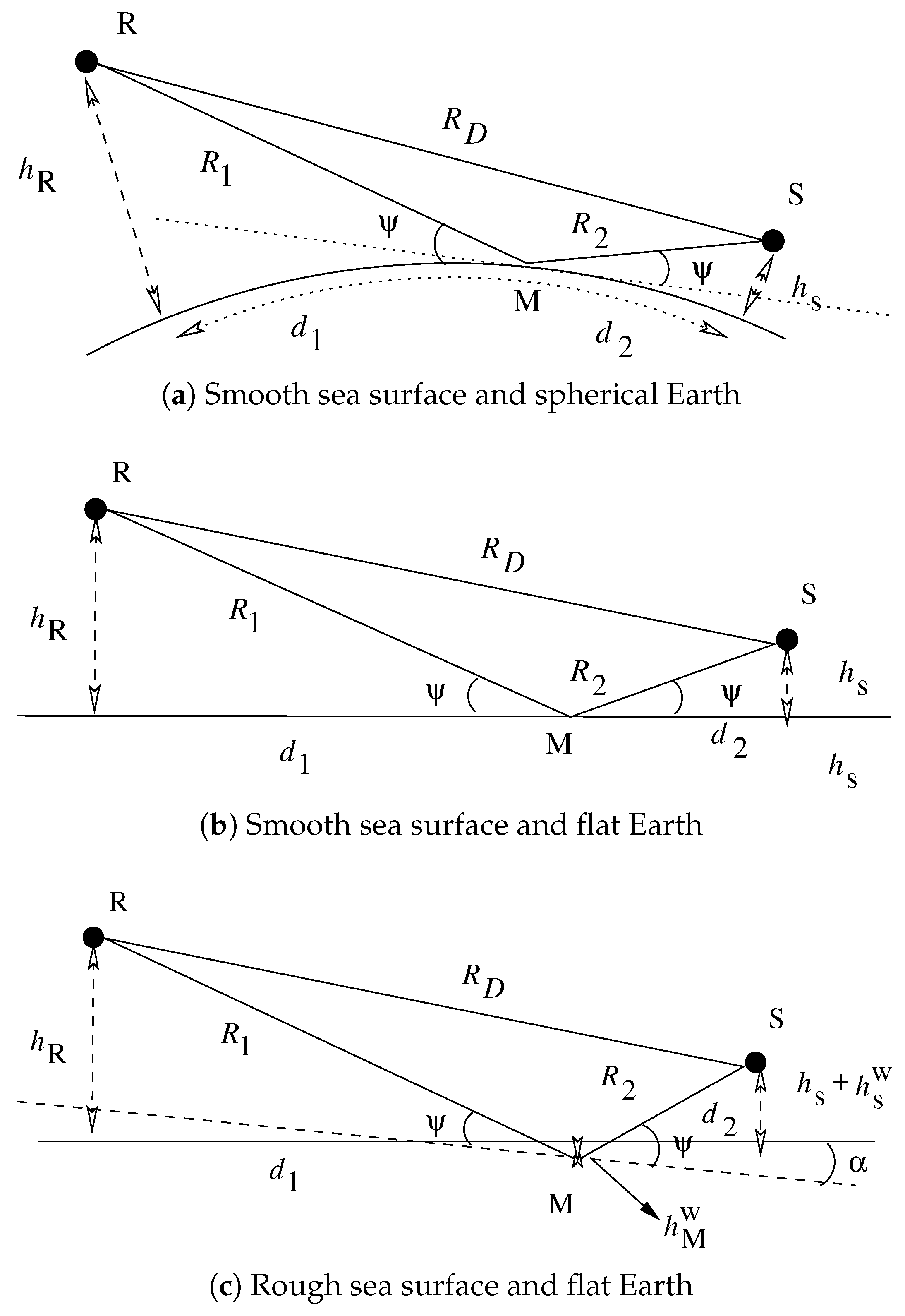
- The direct path return corresponds to the signal that propagates toward and from the ship along the path . The length of this path is denoted (the round trip length is ).
- The direct-indirect path return follows either the path or the path . It is the first order multipath since there is only one reflection over the sea surface. The length of the path is denoted and the total length of this path is . Since the EM wave can be reflected first either on the sea surface or on the point scatterer, there are two direct-indirect paths that are coherently added at the receiver.
- The indirect path corresponds to the path , which is the second order multipath with two reflections over the sea surfx1ace, the round trip length being .
2.2. Sea Surface Model and Roughness
2.3. Attenuation and Scattering
- is the Fresnel reflection coefficient which depends on the EM wave polarization, the grazing angle (see Figure 1) and the sea relative permittivity that is and . The sea dielectric constant is a function of the radar frequency, the salinity and the sea surface temperature [46]. We adopt the following conditions: a sea temperature of 20 C, a sea salinity of 35 PSU and for the considered frequency range we have .
- is the specular attenuation due to surface roughness. Under the assumption of gaussianity for the wave heights, Ament [9] (Equation (6a)), Miller and Brown [41] (Equation (6b)) and Beard [45] (Equation (6c)) derived the following expressions:with the modified Bessel function of order 0. The different attenuation factors are drawn in Figure 3 for different frequency values and incident angles.
- D is the divergence, depending on the geometry model and the values of which are given in Table 2.
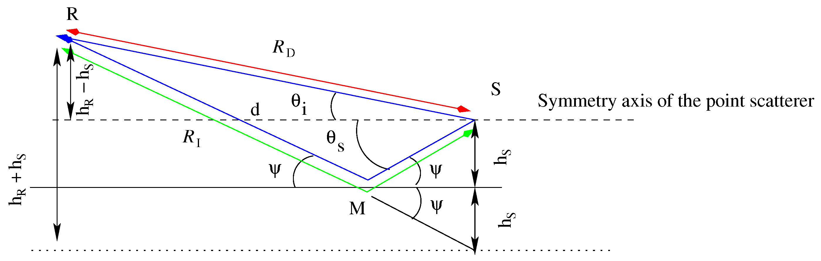
- is the monostatic target RCS in the direct path direction with an incident/backscattering angle of (see Figure 2), the reference being the symmetry axis of the point scatterer assumed laying in the horizontal plane. is the monostatic target RCS in the indirect path (incident/backscattering angle of (Figure 2)). is the Indirect/Direct bistatic RCS (incident angle /backscattering angle and the Direct/Indirect bistatic RCS incident angle /backscattering angle , see Figure 2). We have considered three kinds of scatterer for which the monostatic ( and ) and the bistatic ( and ) RCSs are given in Table 3. For an isotropic point scatterer such as the sphere, we have . and can be different such as in the case of the cylinder. For this point scatterer, when the incident/scattering angles are not close to the horizontal plane and , then the backscattered energy is weak. The trihedral is a difficult scatterer for our approach since it is a well know isotropic scatterer for monostatic RCSs, but not for bistatic RCSs (unlike the sphere) thus the direct-direct and indirect-indirect backscattering can be fairly strong while the direct-indirect backscattering can be weak, thus leading to a confusion between the two replicas and to a estimate that is twice the true value. In Section 4, we test our algorithm for small scatterers that is m for the sphere, m m for the cylinder and m for the trihedral and large scatterers with the dimension m, m m and m.
2.4. Delay
3. Point Scatterer Height Estimation
3.1. Resolved and Unresolved Replicas
3.2. Estimate
- The most obvious case is when there is not any detected replica. An example of this case is given in Figure 6, in which we do not observe any replicas for = 1000 m for both polarizations (a) and (b) while replicas are observed for = 300 m (c) and (d). However for VV polarization (d), the replica has the same level as the noise for a resolution of m (blue dotted line) and cannot be detected, unlike for m (dotted green line). In the HH case, several replicas are observable and thus can be robustly estimated.
- A less frequent case is when the replicas are not detected but a spurious (noise) peak is detected leading to a false scatterer height estimate. Some estimates are wrong and coherent (we discuss this point below), but some other values overpass the current point scatterer heights on a ship (that we limit the ship air draught to 60 m).
- Low scatterer height can be missed when the direct backscattering and the replicas are too close to be distinguished (obviously the limit case is a height of 0 m for which all the replicas overlap).
- High scatterer height can suffer of spurious peaks due to a larger number of time samples between the direct backscattering and the replicas.
4. Simulation and Results
4.1. Sea Parameters
4.2. Radar Parameters
4.3. Scene Geometry
4.4. Discussion
- As stated in Section 2.1, we have limited our study to one point scatterer with its replicas. This may be unrealistic since, for an antenna (real) aperture of , the imaged area is 175 m large at 10 km and then can contain several scatterers. In Figure 11, we have depicted the case of the joint backscattering of the two scatterers. For estimating the height, these scatterers is reduced to determine the pairing between the direct backscattering with its corresponding replica. Since, we consider configurations for which the radar is above the ship, the direct backscattering are the two first detected peaks. Moreover the direct backscattering of the highest point (20 m in our case) corresponds the first peak (since it has the smallest path length) while its corresponding replica is the latest one (largest path length). For VV polarization, the pairing is fairly straightforward since only the direct-indirect replica can be observed, with the drawback that if only the direct backscattering (of each point scatterer) is detected, then we conclude that only one scatterer is present at a false altitude, which is the difference of height of the two scatterers. For HH polarization, the pairing links the direct backscattering and the indirect replica. Thus in order to avoid false estimate, the peak equally distant (corresponding to the direct-indirect case) from these two extremals (direct and indirect replicas) has to be removed before continuing the pairing for the other point scatterer. Once, the highest point scatterer height is estimated, the peaks of its direct backscattering and its replica have to removed, and then the process is iterated with second highest point scatterer and can be generalized to several scatterers. Obviously, more complex scenario with lacking replicas can occur. It this case, the comparison of several pulse results can remove incoherent/false height estimates.
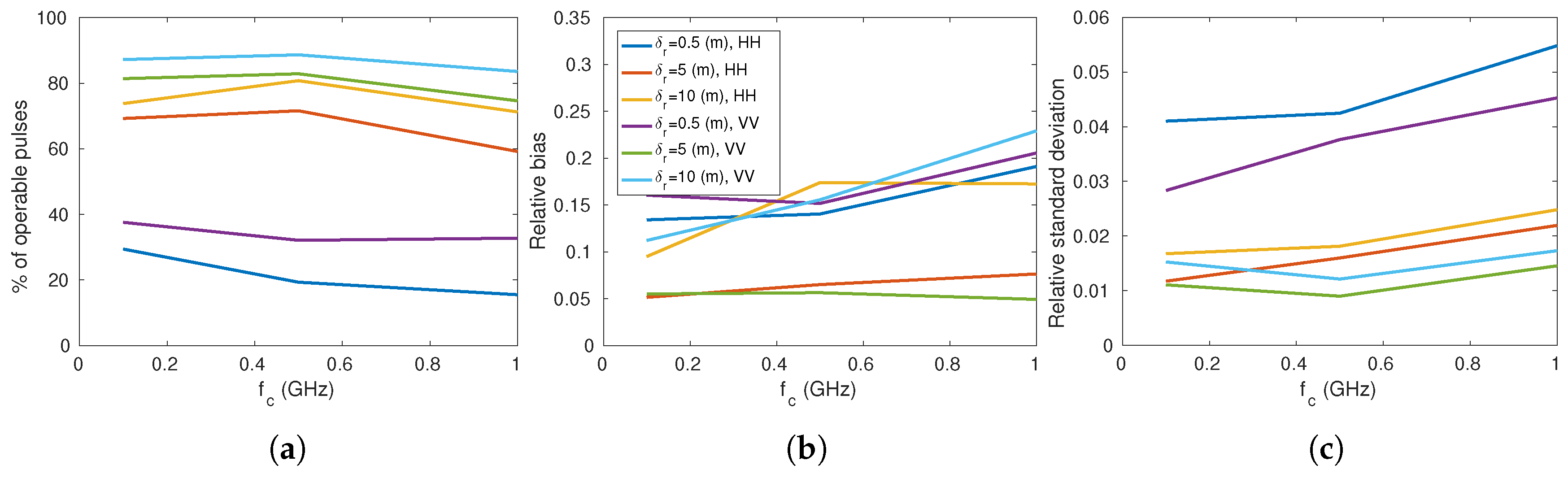
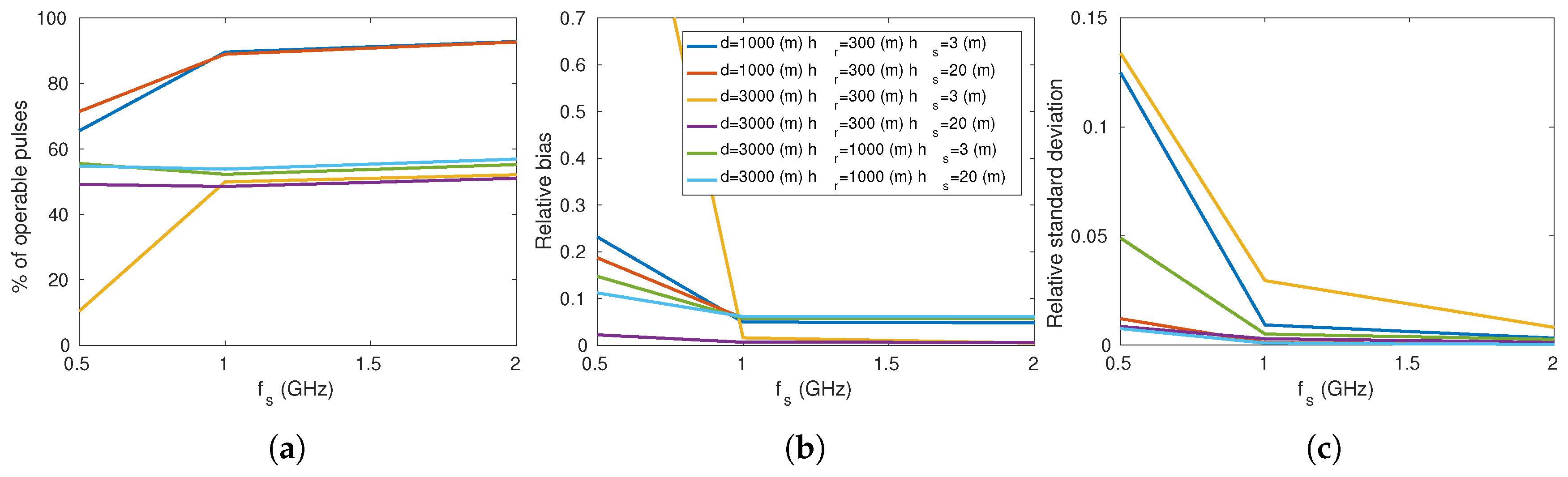
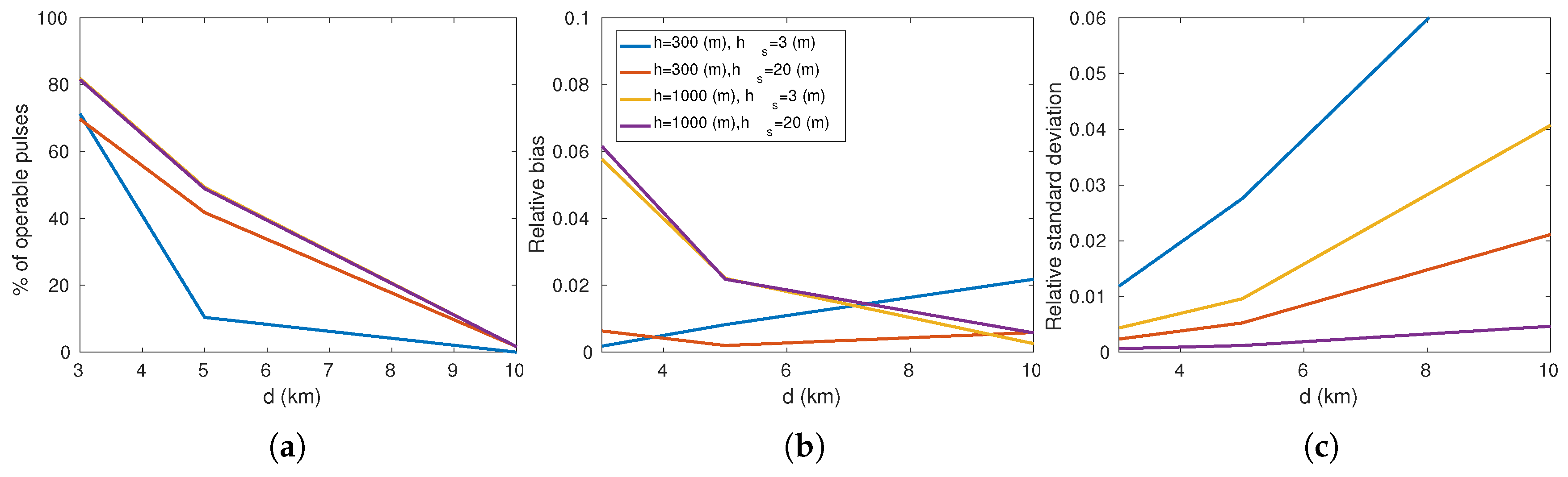
- As seen in the previous section, detecting peaks in the inverse Fourier transform of , due to direct and indirect backscattering, is hampered by first a too large bandwidth and second a too weak sampling frequency. A more drastic limitation is the radar-target distance. Apart the hardware (mean power, sampling frequency) several algorithmic improvements are possible. For instance the level of detection can be decreased and thus the probability of peak detection (due to replica) increases, increasing thus the number of operable pulses. misestimates can be identified by comparing the results of estimates for all the pulses (through the histogram or clustering algorithm for instance). Moreover, more refined algorithms (than thresholding value for detecting peaks) could also improve the results of our approach for operational conditions. For instance a MUSIC approach [27] can be applied in the frequency domain to determine the peak location in the time domain. Others algorithms, such as Weighted Fourier Transform and RELAXation based (WRELAX) [59] devoted to the delay estimation could also be applied to our multipath detection problem and lead to more robust results.
5. Conclusions
Author Contributions
Funding
Conflicts of Interest
Appendix A. Path Difference Formulas for a Spherical Earth
References
- Wehner, D.R. High Resolution Radar; Artech House: Norwood, MA, USA, 1995. [Google Scholar]
- Potter, L.; Moses, R. Attributed scattering centers for SAR ATR. IEEE Trans. Image Process. 1997, 6, 79–91. [Google Scholar] [CrossRef] [Green Version]
- Belloni, C.; Balleri, A.; Aouf, N.; Merlet, T.; Le Caillec, J.M. SAR Image Dataset of Military Ground Targets with Multiple Poses for ATR. In Proceedings of the SPIE Security + Defence 2017: Target and Background Signatures III, Warsaw, Poland, 11–14 September 2017; Volume 10432. [Google Scholar]
- Laribi, A.; Hahn, M.; Dickmann, J.; Waldschmidt, C. Vertical digital beamforming versus multipth height finding. In Proceedings of the 2017 IEEE MTT-S International Conference on Microwaves for Intelligent Mobility (ICMIM), Nagoya, Japan, 19–21 March 2017; pp. 99–102. [Google Scholar]
- Sume, A.; Gustafsson, M.; Herberthson, M.; Janis, A.; Nilsson, S.; Rahm, J.; Orbom, A. Radar Detection of Moving Targets Behind Corners. IEEE Trans. Geosci. Remote Sens. 2011, 49, 2259–2267. [Google Scholar] [CrossRef] [Green Version]
- Setlur, P.; Negishi, T.; Devroye, N.; Erricolo, D. Multipath Exploitation in Non-LOS Urban Synthetic Aperture Radar. IEEE J. Sel. Top. Signal Process. 2014, 8, 137–152. [Google Scholar] [CrossRef] [Green Version]
- Zetik, R.; Eschrich, M.; Jovanoska, S.; Thoma, R.S. Looking behind a corner using multipath-exploiting UWB radar. IEEE Trans. Aeros. Electron. Syst. 2015, 51, 1916–1926. [Google Scholar] [CrossRef]
- Barton, D.K. Low-Angle Radar Tracking. In Proceedings of the IEEE; IEEE: Piscataway, NJ, USA, 1974; pp. 687–705. [Google Scholar]
- Ament, W. Towards a theory of reflection by a rough surface. IRE Proc. 1953, 41, 142–146. [Google Scholar] [CrossRef]
- Haspert, K.; Tuley, M. Comparison of predicted and measured multipath impulse responses. IEEE Trans. Aerosp. Electron. Syst. 2010, 47, 1696–1708. [Google Scholar] [CrossRef]
- Duan, C.; Hu, W.; Du, X. Probability Model of multipath delays in radar echoes of scattering centers above ocean surface. Electron. Lett. 2012, 48, 177–179. [Google Scholar] [CrossRef]
- Berizzi, F.; Diani, M. Multipath Effects on ISAR Image Reconstruction. IEEE Trans. Aerosp. Electron. Syst. 1998, 34, 645–653. [Google Scholar] [CrossRef]
- Gao, J.; Su, F.; Cao, X.; Xu, G. Simulation of ISAR Imaging of ships with Multipath Effects. In Proceedings of the Second IEEE Conference on Industrial Electronics and Applications, Harbin, China, 23–25 May 2007; pp. 1484–1488. [Google Scholar]
- Xu, X.; Wang, Y.; Qin, Y. SAR Image modeling of ships over sea surface. In Proceedings of the SAR Image Analysis, Modeling, and Techniques, Stockholm, Sweden, 11–14 September 2006; Volume 6363. [Google Scholar]
- Liu, H.; Su, H.; Shui, P.; Bao, Z. Multipath Signal Resolving and Time Delay Estimation for High Range Resolution Radar. In Proceedings of the IEEE International Radar Conference, Arlington, VA, USA, 9–12 May 2005. [Google Scholar]
- Schimpf, H. The Influence of Multipath on Ship ATR Performance. In Proceedings of the Defense, Security and Sensing 2011 Conference: Automatic Target Recognition XXI, Orlando, FL, USA, 25–29 April 2011; Volume 8049. [Google Scholar]
- Schimpf, H. The mitigation of the influence of Multipath on the Ground-Based Classification of ships. In Proceedings of the 2011 12th International Radar Symposium, Leipzig, Germany, 7–9 September 2011; pp. 787–802. [Google Scholar]
- de Arriba-Ruiz, I.; Perez-Martinez, F.; Munoz-Ferreras, J.M. Time-Reversal-Based Multipath Mitigation Technique for ISAR Images. IEEE Trans. Geosci. Remote Sens. 2013, 51, 3119–3139. [Google Scholar] [CrossRef]
- Bar-Shalom, Y.; Kumar, A.; Blair, W.D.; Groves, G.W. Tracking Low Elevation Targets in the presence of multipath propagation. IEEE Trans. Aerosp. Electron. Syst. 1994, 30, 973–980. [Google Scholar] [CrossRef]
- Bruder, J.A.; Saffold, J.A. Multipath Effects on low-angle tracking at millimetre-wave frequencies. In IEE Proceedings F—Radar and Signal Processing; IET: Stevenage, UK, 1991; Volume 138, pp. 172–185. [Google Scholar]
- Chung, M.S.; Lim, J.S.; Park, D.C. Monopulse Tracking with Phased Array Search Radar in the presence of specular reflection from sea surface. IEEE Trans. Aerosp. Electron. Syst. 2006, 42, 1459–1463. [Google Scholar]
- Krim, H.; Viberg, M. Two Decades of Array Signal Processing Research. IEEE Trans. Signal Process. 1996, 13, 67–94. [Google Scholar] [CrossRef]
- Krim, H.; Proakis, J.G. Smoothed eigenspace-based parameter estimation. Autom. Spec. Issue Stat. Signal Process. Control 1994, 30, 27–38. [Google Scholar] [CrossRef]
- Akaike, H. Information Theory and an extension of the maximum likelihood principle. In Proceedings of the 2nd International Symposium on Information Theory, Tsahkadsor, Armenia, 2–8 September 1971; pp. 267–281. [Google Scholar]
- Rissanen, J. Modeling by shortest data description. Automatica 1978, 14, 465–471. [Google Scholar] [CrossRef]
- Cho, C.M.; Djuric, P.M. Detection and Estimation of DOA’s of Signals via Bayesian Predictive Densities. IEEE Trans. Signal Process. 1994, 42, 3051–3061. [Google Scholar]
- Schmidt, R.O. Multiple Emitter Location and Signal Parameter Estimation. Ph.D. Thesis, Stanford University, Stanford, CA, USA, 1981. [Google Scholar]
- Shtager, E.A. An estimation of sea surface influence on radar reflectivity of ships. IEEE Trans. Antennas Propag. 1999, 47, 1623–1627. [Google Scholar] [CrossRef]
- Sletten, M.A.; Trizna, D.B.; Hansen, J.P. Ultrawide-Band Radar Observations of Multipath Propagation over the sea surface. IEEE Trans. Antennas Propag. 1996, 44, 646. [Google Scholar] [CrossRef]
- Karimian, A.; Yardim, C.; Gerstoft, P.; Hodgkiss, W.; Barrios, A. Multiple Grazing Angle sea clutter Modelling. IEEE Trans. Antennas Propag. 2012, 60, 4408–4417. [Google Scholar] [CrossRef]
- Assembly, T.I.R. RECOMMENDATION ITU-R P.372-12; Technical Report; International Telecommunication Union: Geneva, Switzerland, 2015. [Google Scholar]
- Lake, B.; Yuen, H.; Rungaldier, H.; Ferguson, W. Nonlinear deep-water waves; theory and experiments parts 2 Evolution of a continuous wave train. J. Fluid Mech. 1977, 83, 49–77. [Google Scholar] [CrossRef]
- Elfouhaily, T.; Thomson, D.; Vandemark, D.; Chapron, B. Truncated Hamiltionian versus surface perturbation in nonlinear wave theories. Waves Random Media 2000, 10, 103–116. [Google Scholar] [CrossRef]
- Barrick, D.; Weber, B. On the nonlinear theory for gravity waves on the ocean’s surface. Part II: Interpretation and applications. J. Phys. Oceanogr. 1977, 7, 11–21. [Google Scholar] [CrossRef]
- Krasitskii, V. On the reduced equations in the Hamiltonian theory of weakly nonlinear surface waves. J. Fluid Mech. 1994, 272, 1–20. [Google Scholar] [CrossRef]
- Hasselmann, K. On the non-linear energy transfer in a gravity-wave spectrum. Part 1 General Theory. J. Fluid Mech. 1961, 12, 481–500. [Google Scholar] [CrossRef]
- Elfouhaily, T.; Thompson, D.; Vandemark, D.; Chapron, B. Weakly nonlinear theory and sea bias estimations. J. Geophys. Res. 1999, 104, 7641–7647. [Google Scholar] [CrossRef]
- Hara, T.; Plant, W. Hydrodynamic Modulation of Short Wind-Wave Spectra by Long Waves and its Measurement Using Microwave Backscatter. J. Geophys. Res. 1994, 99, 9767–9784. [Google Scholar] [CrossRef]
- Hasselmann, K.; Raney, R.; Plant, W.; Alpers, W.; Schuman, R.; Lyzenga, D.; Rufenach, C.; Tucker, M. Theory of Synthetic Aperture Radar Ocean Imaging: A MARSEN view. J. Geophys. Res. 1985, 90, 4659–4686. [Google Scholar] [CrossRef]
- Elfouhaily, T.; Chapron, B.; Katsaros, K. A unified directional spectrum for long and short wave. J. Geophys. Res. 1997, 102, 15781–15796. [Google Scholar] [CrossRef]
- Miller, A.R.; Brown, R.M.; Vegh, E. New Derivation for the rough surface reflection coefficient and for the distribution of sea-wave elevations. IEE Proc. H 1984, 131, 114–116. [Google Scholar] [CrossRef]
- TS Hristov, K.A.; Friehe, C. Scattering properties of the Ocean Surface: The Miller-Brown-Vegh model revisted. IEEE Trans. Antennas Propag. 2008, 56, 1103–1109. [Google Scholar] [CrossRef]
- Sinha, A.; Bar-Shalom, Y.; Blair, W.D.; KiruBaraJan, T. Radar measurement extraction in the presence of sea surface multipath. IEEE Trans. Aerosp. Electron. Syst. 2003, 39, 550–567. [Google Scholar] [CrossRef]
- Elfouhaily, T.; Thompson, D.; Linstrom, L. Delay-Doppler analysis of bistatically reflected signals from the ocean surface: Theory and application. IEEE Trans. Geosci. Remote Sens. 2010, 40, 560–573. [Google Scholar] [CrossRef]
- Beard, C. Coherent and Incoherent scattering of microwaves from the ocean. IEEE Trans. Antennas Propag. 1961, 9, 470–483. [Google Scholar] [CrossRef]
- Klein, L.A.; Swift, C.T. An improved model for the dielectric constant of sea water at microwaves frequencies. IEEE Trans. Antennas Propag. 1977, 25, 104–111. [Google Scholar] [CrossRef]
- Blake, L.V. Radar Range Performance Analysis; Chapter all; Artech House: Norwood, MA, USA, 1986. [Google Scholar]
- Zavorotny, V.; Voronovich, A. Two-Scale Model and Ocean Radar Doppler spectra at moderate and low-grazing angles. IEEE Trans. Antennas Propag. 1998, 46, 84–92. [Google Scholar] [CrossRef]
- Arnold-Bos, A.; Khenchaff, A.; Martin, A. Bistatic Radar Imaging of the Marine Environment–Part I: Theoretical background. IEEE Trans. Geosci. Remote Sens. 2007, 45, 3372–3383. [Google Scholar] [CrossRef]
- Voronovich, A. Small-slope approximate for electromagnetic wave scattering at a rough surface interface of two dielectric half-spaces. Waves Random Media 1994, 4, 337–367. [Google Scholar] [CrossRef]
- Voronovich, A.; Zavorotny, V. Theoretical model for scattering or radar signals in Ku- and C-Band from a rough sea surface with breaking waves. Waves Random Media 2001, 11, 247–269. [Google Scholar] [CrossRef]
- Voronovich, A.; Zavorotny, V. Full-Polarization Modeling of Monostatic and Bistatic Radar Scattering from a Rough Sea Surface. IEEE Trans. Antennas Propag. 2014, 62, 1362–1371. [Google Scholar] [CrossRef]
- Voronovich, A.; Zavorotny, V. The effect of steep waves on polarisation Ration at Low Grazing Angles. IEEE Trans. Geosci. Remote Sens. 2000, 38, 366–373. [Google Scholar] [CrossRef]
- Zavorotny, V.; Voronovich, A. Scattering of GPS signals from the Ocean with wind remote sensing application. IEEE Trans. Geosci. Remote Sens. 2000, 38, 951–964. [Google Scholar] [CrossRef]
- Kuttler, J.; Dockery, G. Theoretical description of the parabolic approximation/Fourier split-step method of representing electromagnetic propagation in the troposphere. Radio Sci. 1991, 26, 527–533. [Google Scholar] [CrossRef]
- Levy, M. Parabolic Equation Methods for Electromagnetic Wave Propagation; IET: Stevenage, UK, 2009. [Google Scholar]
- Dockery, G.; Kuttler, J. An improved impedance boundary condition algorithm for Fourier split-step solutions of the parabolic wave equation. IEEE Trans. Antennas Propag. 1996, 36, 1592–1599. [Google Scholar] [CrossRef]
- Peters, L. Passive bistatic radar enhancement devices. Proc. IEE 1962, 109, 1–10. [Google Scholar] [CrossRef]
- Li, J.; Wu, R. An efficient algorithm for time delay estimation. IEEE Trans. Signal Process. 1998, 46, 2231–2235. [Google Scholar]


| Notation | Name | Value |
|---|---|---|
| Central frequency | 0.1 0.5 1 (GHz) | |
| Sampling frequency | 0.5 1 2 (GHz) | |
| Radar resolution | 0.5 5 10 (m) | |
| Polarization | HH VV | |
| PRF | Pulse Repetition Frequency | 50 Hz |
| Sea surface propagation direction | 0 45 90 (degrees) | |
| Wind speed | 5 10 (m) | |
| d | Projected distance between the radar and the point scatterer | 1 3 5 10 (km) |
| Height of the radar | 10, 300, 1000 (m) | |
| Height of scatterer | 3, 20 (m) | |
| Sea surface height at the reflection point | ||
| Sea surface height at the scatterer location |
| Geometric Model | D | Reference | |
|---|---|---|---|
| Smooth sea surface and spherical earth | [47] | ||
| Smooth sea surface and flat earth | 1 | ||
| Rough sea surface and flat earth | 1 | [11] |
| Point Scatterer | Monostatic RCS | Bistatic RCS |
|---|---|---|
| Sphere | ||
| Cylinder | ||
| Trihedral |
| Percentage | Relative | Relative | |
|---|---|---|---|
| of Operable Pulses | Bias | Standard Deviation | |
| HH | 66.75 | 12.2 | 1.76 |
| VV | 54.45 | 11.5 | 2.24 |
| Sphere ( m) | 54.49 | 6.97 | 1.72 |
| Sphere ( m) | 75.55 | 14.56 | 2.39 |
| Cylinder ( m, m) | 36.14 | 10.10 | 1.39 |
| Cylinder ( m, m) | 72.62 | 14.01 | 2.48 |
| Trihedral ( m) | 53.86 | 12.02 | 1.81 |
| Trihedral ( m) | 71.08 | 12.15 | 1.88 |
| m | 43.54 | 18.74 | 2.51 |
| m | 54.75 | 8.30 | 1.09 |
| m | 58.17 | 17.20 | 3.65 |
| m | 63.03 | 6.68 | 0.34 |
© 2019 by the authors. Licensee MDPI, Basel, Switzerland. This article is an open access article distributed under the terms and conditions of the Creative Commons Attribution (CC BY) license (http://creativecommons.org/licenses/by/4.0/).
Share and Cite
Le Caillec, J.-M.; Habonneau, J.; Khenchaf, A. Ship Profile Imaging Using Multipath Backscattering. Remote Sens. 2019, 11, 748. https://doi.org/10.3390/rs11070748
Le Caillec J-M, Habonneau J, Khenchaf A. Ship Profile Imaging Using Multipath Backscattering. Remote Sensing. 2019; 11(7):748. https://doi.org/10.3390/rs11070748
Chicago/Turabian StyleLe Caillec, Jean-Marc, Jérôme Habonneau, and Ali Khenchaf. 2019. "Ship Profile Imaging Using Multipath Backscattering" Remote Sensing 11, no. 7: 748. https://doi.org/10.3390/rs11070748