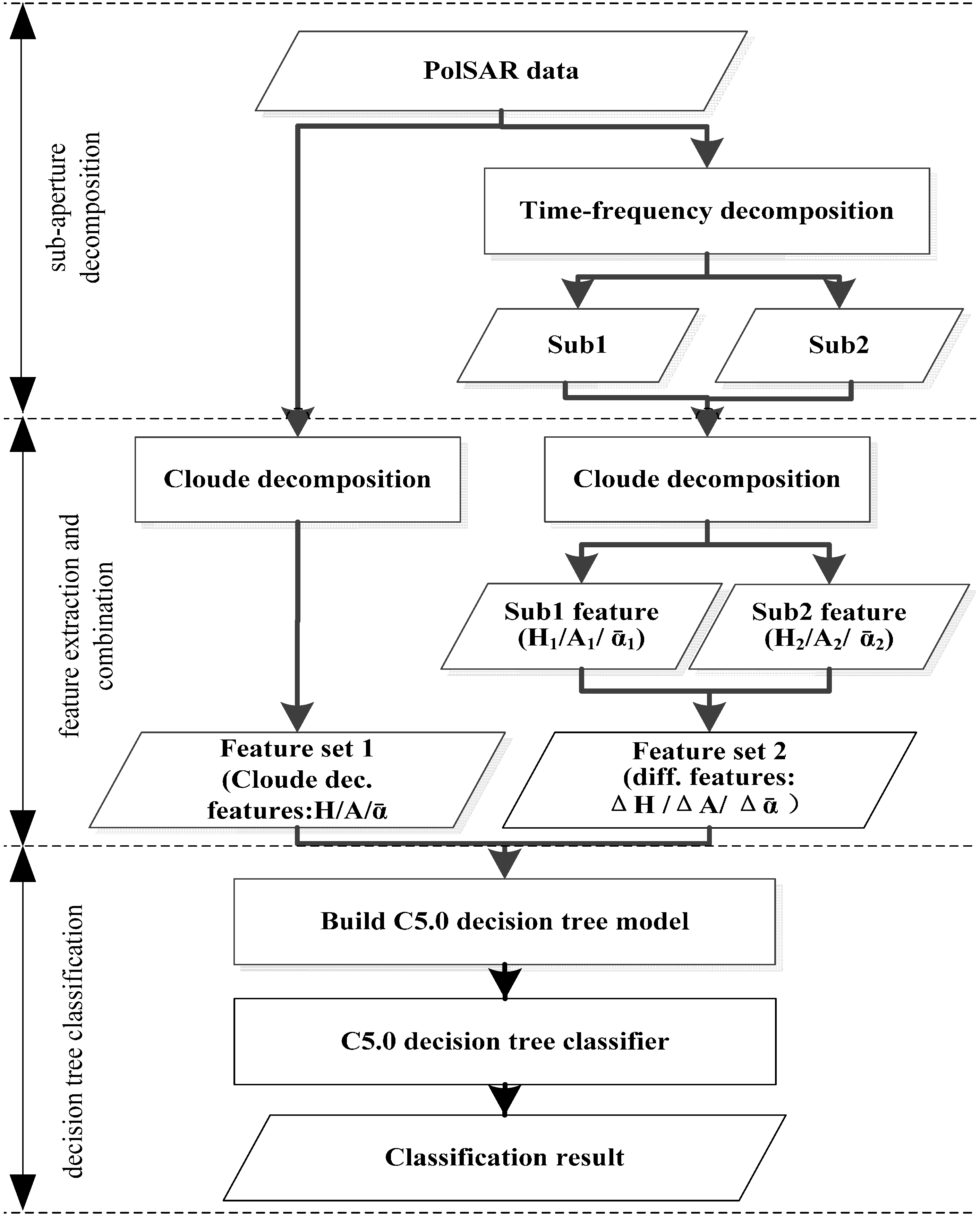
Figure 3.
Flow chart of the PolSAR image classification combining with the sub-aperture decomposition.
3.2. Feature Extraction and Combination
Cloude–Pottier decomposition is applied to the PolSAR images to obtain the feature set 1: scattering entropy (H), anisotropy (A) and scattering angle () The Cloude–Pottier decomposition is also conducted on the two sub-aperture images, respectively, and feature set 2, with its elements of ΔH, ΔA and is obtained through the differences between H, A and of each sub-aperture image, respectively. Feature set 1 and 2 are combined to form the feature set for the target identification. The technology is introduced in detail as follows.
Cloude–Pottier decomposition [
22] is an eigenvector analysis method based on coherence matrix. The polarimetric coherence matrix [
T] is decomposed into the sum of three independent coherence matrices [
Tn]:
where
i represents the scattering mechanism;
denotes an independent coherence matrix with rank 1 under a certain scattering mechanism;
denotes the eigenvalue, which represents the intensity of the scattering mechanism;
is the eigenvector, which can be written as:
where
corresponds to the physical mechanism of the process of target scattering, and its range is 0°~90°;
denotes the azimuth angle of the target relative to the radar line-of-sight;
,
, and
are phase angles of target scattering [
22]. In order to better describe the stochastic characteristics of media, Cloude and Pottier [
10,
23] gave the definitions as follows:
where
is the probability obtained from the eigenvalue of [
T].
H is the scattering entropy (0 ≤
H ≤ 1), and represents the stochastic characteristic of the target from isotropic scattering (
H = 0) to complete stochastic scattering (
H = 1).
is the scattering angle, representing the change of average scattering mechanisms from odd scattering (
= 0°) to dipole scattering (
= 45°) and then to even scattering (
= 90°) [
23]. The anisotropy
A characterizes the relative magnitudes of the second and third eigenvalues. A 5 × 5 window was chosen when calculating H/alpha decomposition.
As a result of Cloude–Pottier decomposition to the full-resolution PolSAR image, entropy (
H), anisotropy (
A) and alpha (
) are taken as feature set 1. Besides, the differences information (ΔH, ΔA and
) between the results of the Cloude–Pottier decomposition to the two sub-aperture images are taken as feature set 2, which is defined as follows:
where
,
and
(
) represent polarimetric entropy, anisotropy and average scattering angle of the two sub-apertures. Feature set 2 are combined with feature set 1 to identify ground targets.
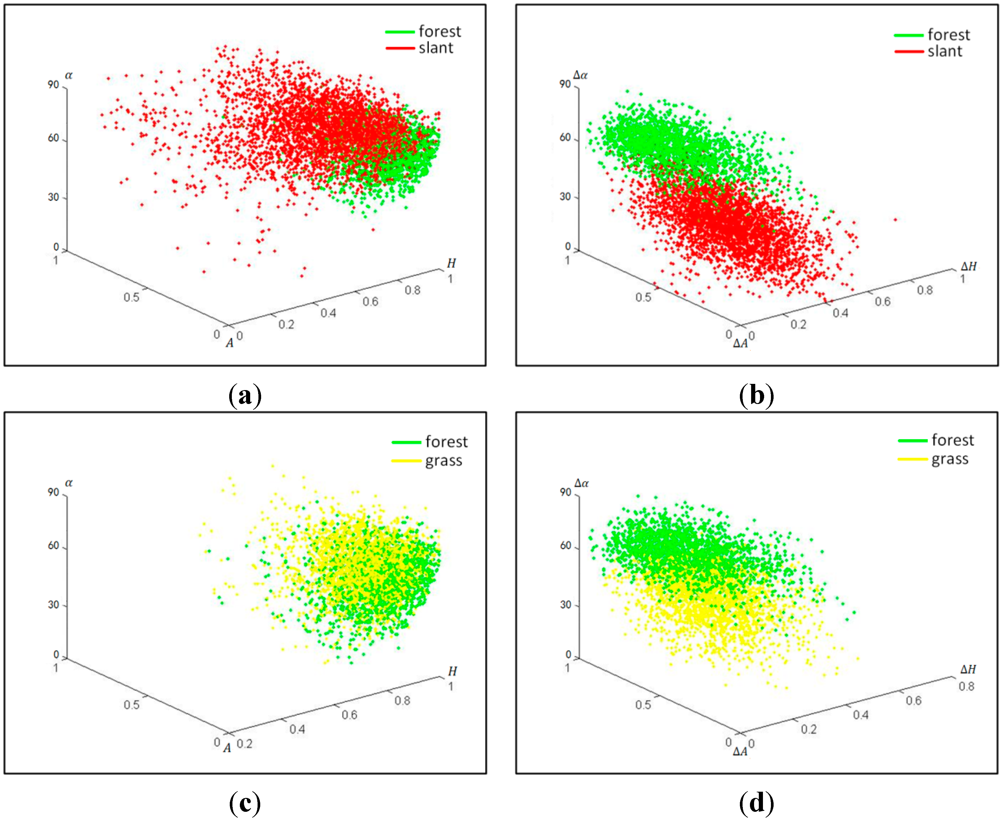
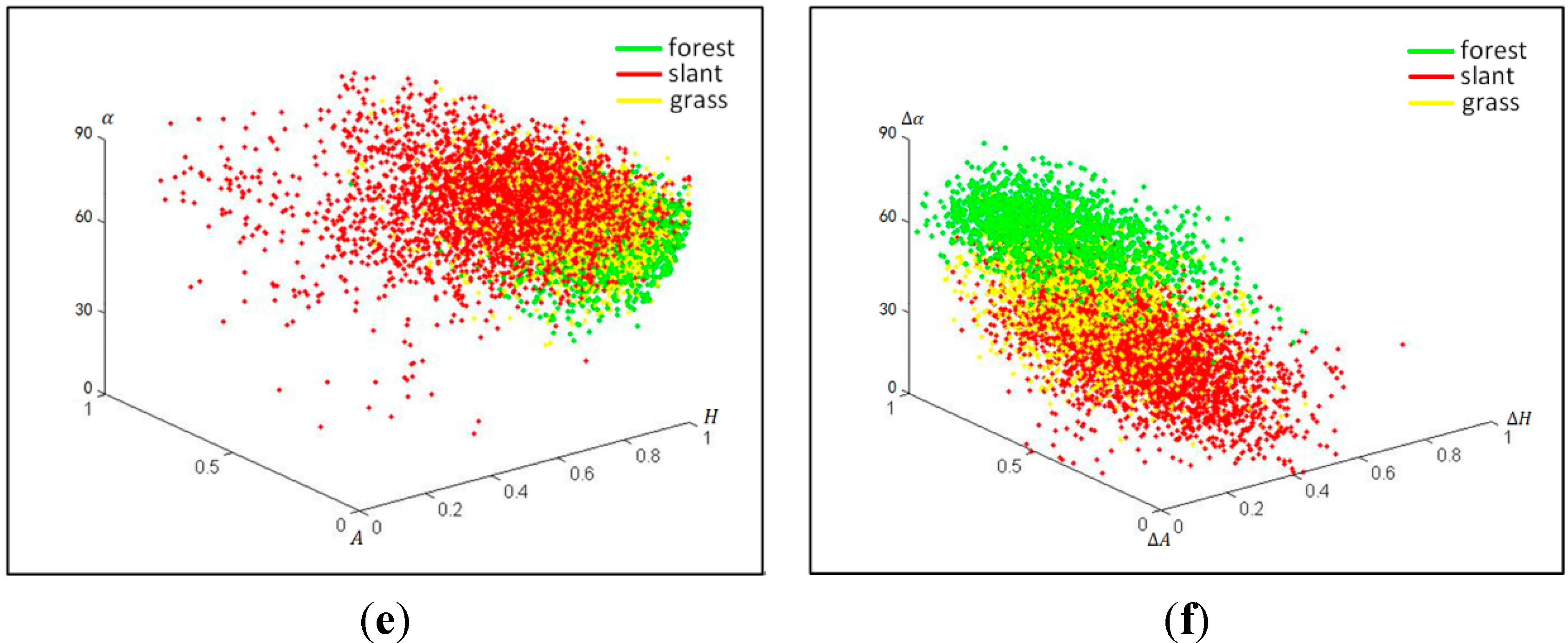
To further understand the capability of distinguishing ground features using feature set 1 and 2, the training samples of forest, grassland and slant-buildings were selected, and their scatter diagrams were plotted using feature set 1 and 2, respectively (
Figure 4). Red points are the slant-buildings, green points are forest and yellow points are grassland.
As shown in
Figure 4, feature set 2 can distinguish slant-buildings from forest (
Figure 4b), and it can improve the separability between forest and grassland (
Figure 4d). In
Figure 4f, grassland and slant-buildings are mixed slightly but it performs better than feature set 1 (
Figure 4e). In summary, feature set 2, compared with feature set 1, can mine more information from the original PolSAR image, and is more suitable for ground feature identification.
Figure 4.
The scatter diagrams of forest, slant-buildings and grassland in feature set 1 and 2. Scattering entropy (H), anisotropy (A) and scattering angle () are decomposed from the PolSAR image. The same Cloude–Pottier decomposition is also conducted on the two sub-aperture images, respectively, and feature set 2, with its elements ΔH, ΔA and , is obtained through the differences between H, A and of each sub-aperture image, respectively. (a) Feature set 1: forest and slant-buildings; (b) Feature set 2: forest and slant-buildings; (c) Feature set 1: forest and grassland; (d) Feature set 2: forest and grassland; (e) Feature set 1: forest, grassland and slant-buildings; (f) Feature set 2: forest, grassland and slant-buildings.
3.3. Decision Tree Classification
Different from the Maximum Likelihood classification method based on the statistical distribution function, the decision tree is a classifier with high speed, high accuracy, simple generation mode and applicability to large datasets [
24]. Not requiring pre-decided data distribution, this algorithm is popularly used in data mining for complicated, non-linear mapping. Here we used C5.0 [
25] decision tree to construct the classification rules because it has the following features: (1) generation of intuitive rules, enhancing user understanding of the algorithm; (2) robustness to missing data; (3) fast operation speed; (4) a powerful boosting technique,
i.e., boosting and cost-sensitive tree building [
26].
In this study, feature set 1 and the 2 were combined into a multichannel image. A feature vector was then formed for each of the selected 25,952 pixels (
Table 1). Twelve thousand nine hundred and ninety-five training pixels (vectors) were used to develop the C5.0 decision tree model, and then the classification result is applied to the 12,957 validation pixels using the developed C5.0 tree to evaluate the classification accuracy.


