3.2.1. Data Preparation
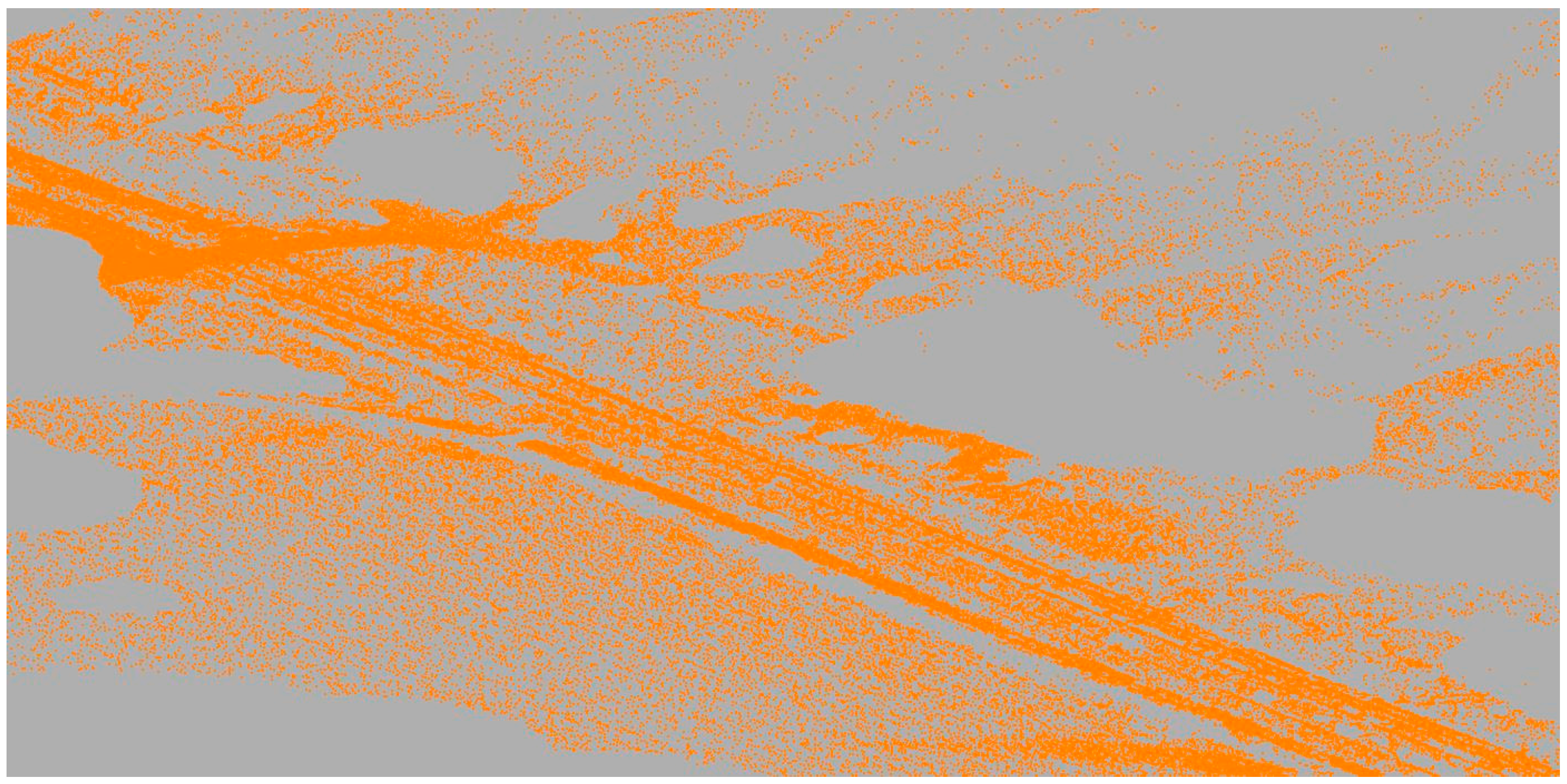
Data preparation consists of the following three procedures, ground filtering, reducing point cloud size and setting the calculation order. Firstly, ground filtering has to be performed. This procedure is necessary for calculating the coordinates of the detected support structure on the ground. The classification might be executed by a number of algorithms, but as it was not the main goal of this work, it was decided to use ground classification algorithms found in the TerraScan software (version 016.003). The results show typical holes in the terrain that arise due to the occlusions (
Figure 6). As the classification objective is to provide the elevation coordinates for the positions of the support structures situated directly next to the rail track, the results are sufficient.
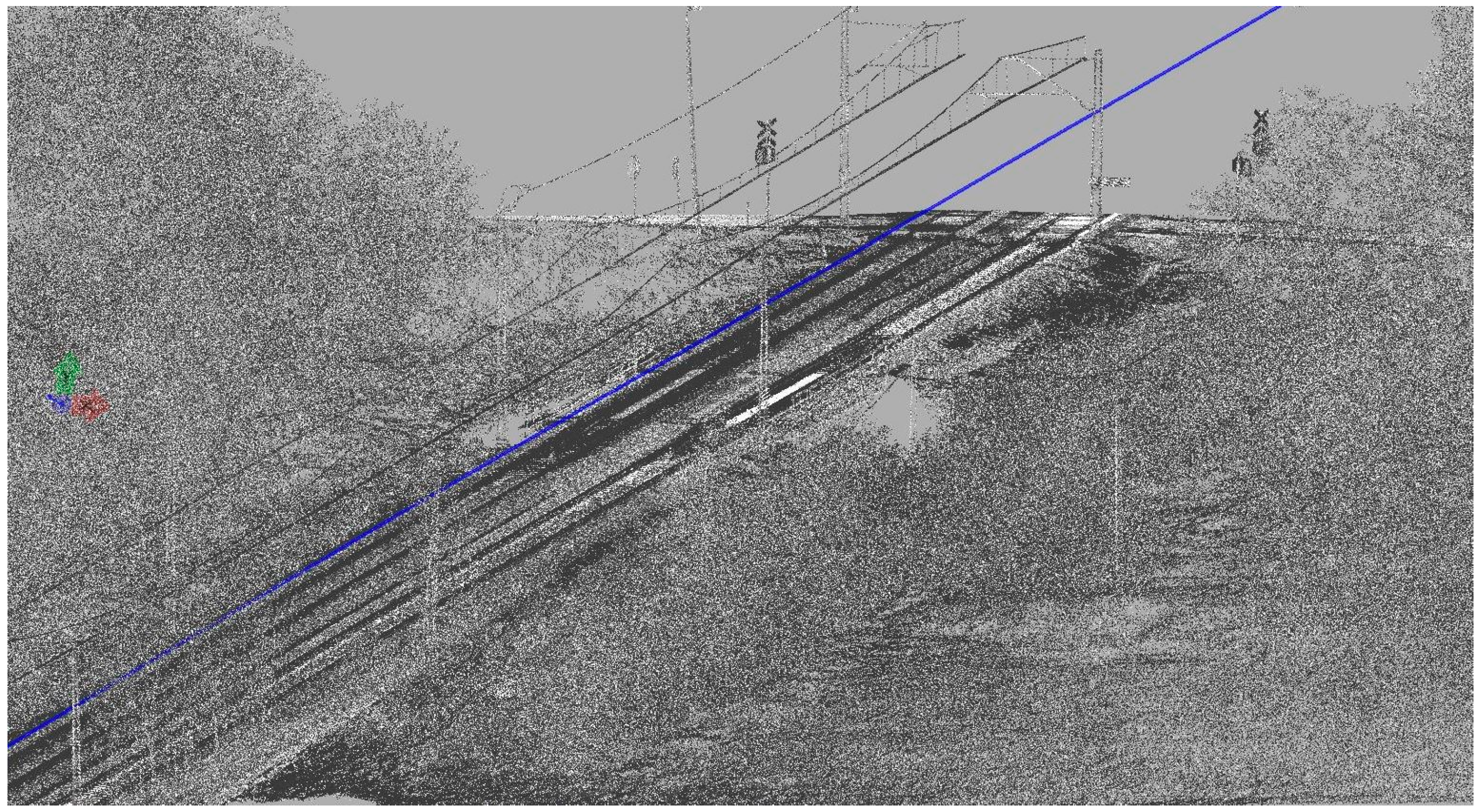
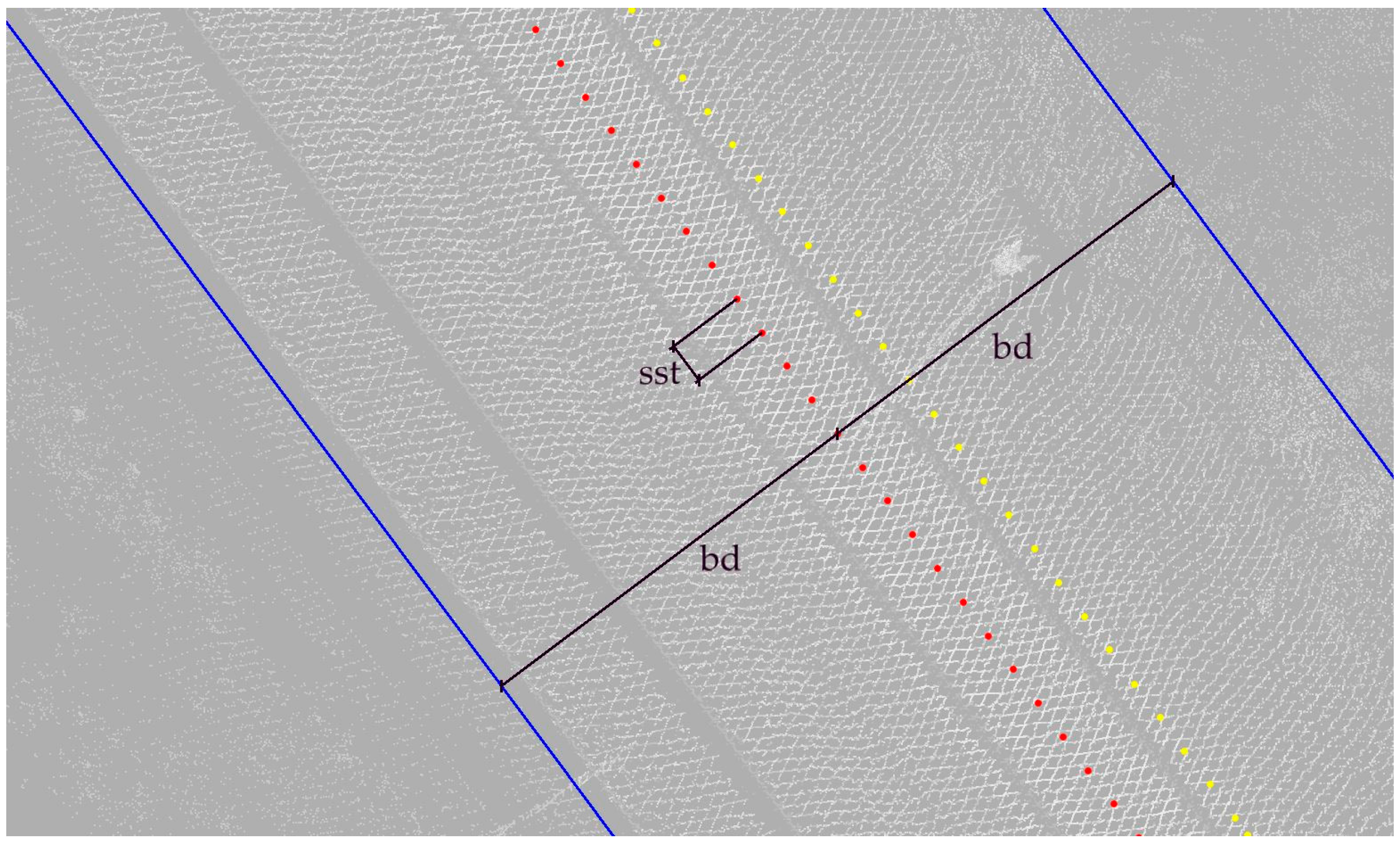
The second procedure limits the calculations of the later algorithm to points positioned up to a set distance horizontally from the registered trajectory: bd (
Figure 7). It is necessary to set the limit according to regulations in force in the area where the survey took place. The limit should incorporate both railway clearance monitoring maximum distance, as well as the maximum distance from the track to one line support structure.
To keep order in point cloud processing and to be able to directly relate to specific parts of the data, an indexing system has been introduced. The processed point cloud is divided into sections along the route. Subsequent sections are given one, unchangeable index i {1, 2, 3...}. Each section is defined by its trajectory key point (KP
i), directional point (DP
i) and section depth (sd). Sets of consecutive key points (KP
i) and directional points (DP
i) are derived from the trajectory in established, even intervals, section steps (sst) (
Figure 7). Key points belong directly to the trajectory. Each KP
i together with its corresponding DP
i forms a horizontal line perpendicular to the trajectory in said KP
i. The DP
i is positioned to the right of the trajectory, but its distance is of no importance and, as such, has been set to 1 m. Section i (S
i) is then a set of points lying within half a section depth from the vertical plane containing appropriate KP
i and DP
i.
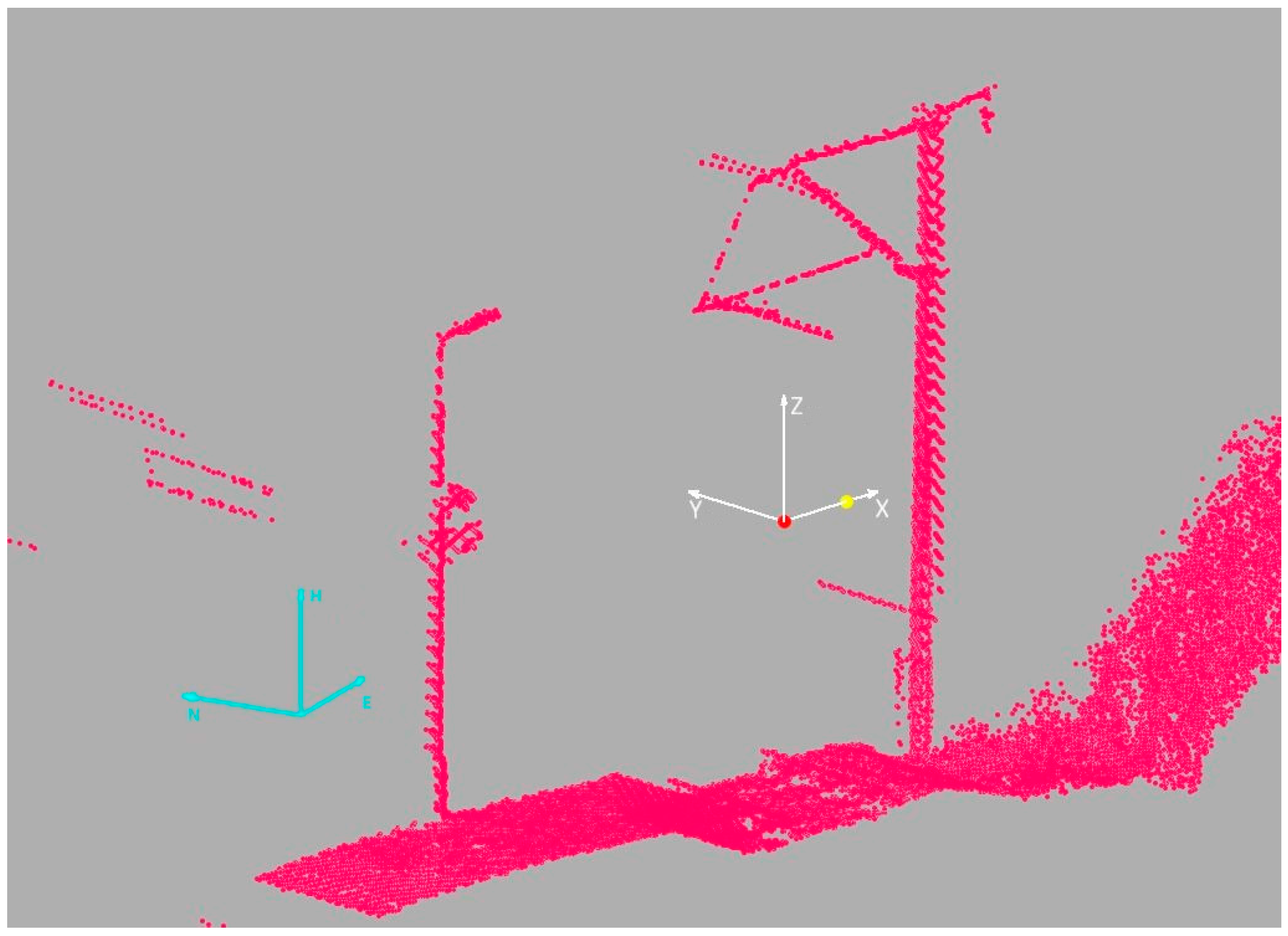
Two coordinate systems also need to be defined. The first coordinate system, the projected ENH (easting, northing, elevation) in which the MLS data are provided. The other is the local coordinate system X
iY
iZ
i, which is different for each section S(i) (
Figure 8). Its origin lies in the KP
i; the X
i axis is directed towards the DP
i (off-track direction); the Y
i axis is perpendicular anti-clock-wise to the X
i axis (along the track direction); and the Z
i axis is parallel to the H axis of the projected ENH coordinate system. Units between the coordinate systems remain the same.
3.2.2. Initial Density Analysis
As previously explained, the design method uses geometric relationships in the MLS data. Point density is used to limit the search for support structures. A matrix is created with one column and rows corresponding to the index i. The value of the i-th cell is a number of points within an i-th section at a set distance from the trajectory both horizontally and vertically:
where
where, S(i), set of points belonging to section i; h
l, h
h, elevation distance limits; d, horizontal distance limits along the X axis.
Additionally, for each section, a region boundary is saved. Border vertices are calculated using the maximum values of the coordinates of the set of section points in the local 2D coordinate system, anchored in the trajectory key point and set in the section plane. Points lying within the calculated boundaries are assigned to the class catenary system. The lower left vertex (LL) is calculated:
where
XLL, lowest X coordinate value within points in the subset T,
ZLL, lowest Z coordinate value within points in the subset T.
Accordingly, the upper right vertex (UR):
where
XUR, highest X coordinate value within points in the subset T,
ZUR, highest Z coordinate value within points in the subset T.
The statistical parameters of the density matrix have been calculated to provide the information necessary to establish the correct binarization threshold. Firstly, the average number of points per section and, then, the population standard deviation are calculated.
where
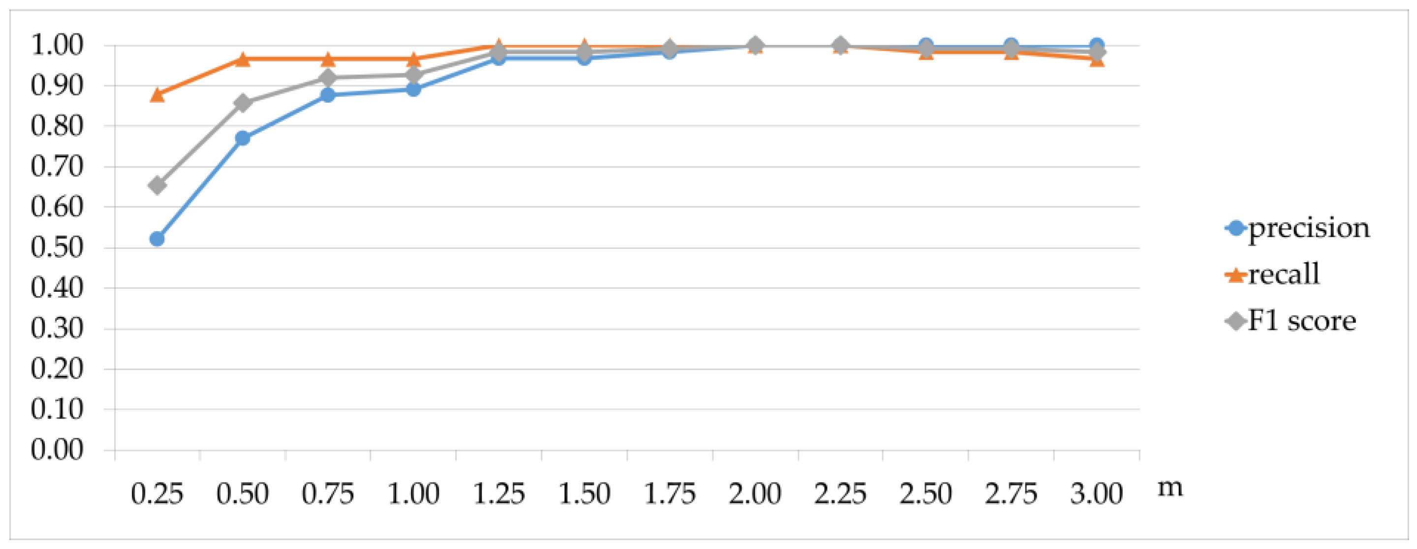
The matrix is then binarized with a threshold equal to the average number of points together with m times the population standard deviation [
32]:
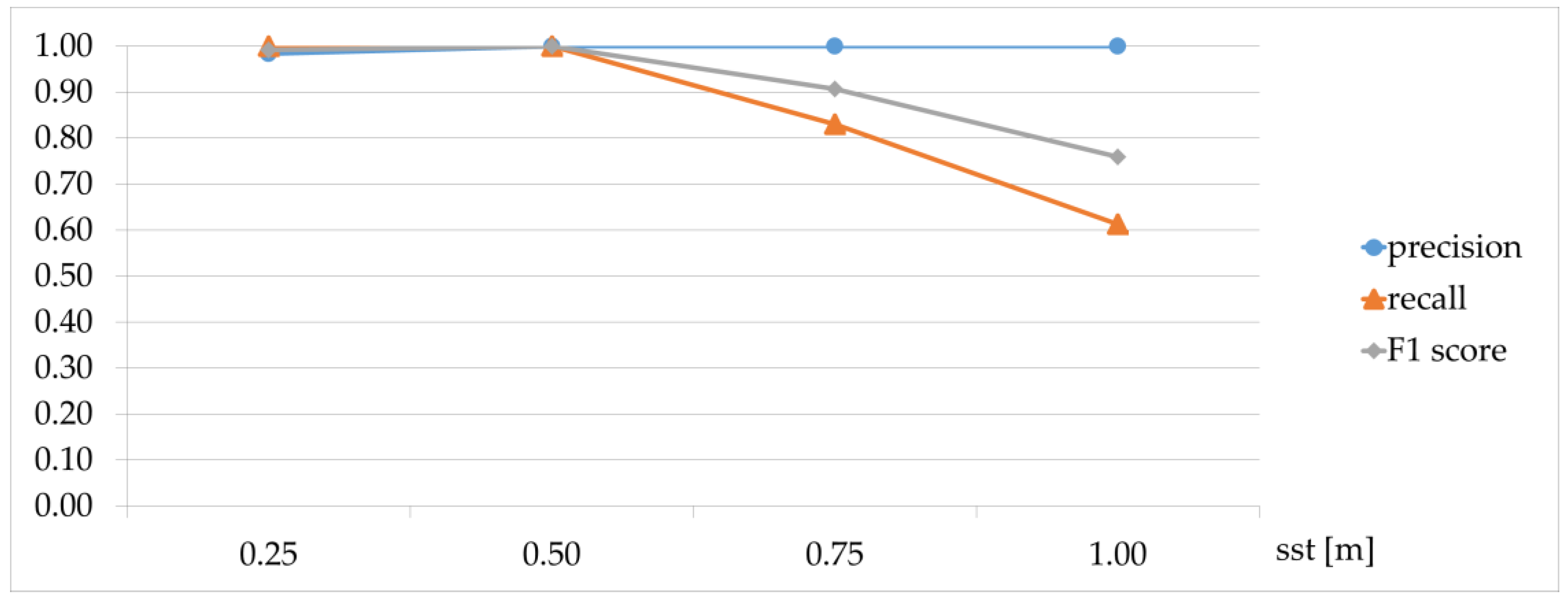
The value of the m parameter was determined during threshold sensitivity analysis in
Section 5.1.
Then, the process, similar to morphological image processing, dilatation, is conducted to gather areas of interest lying in the near vicinity. A circle with a radius equal to 1 matrix unit has been used as a structuring element. Next, all existing area centers are found, and their index numbers (row numbers) are derived, to form a set of places of interest (W).
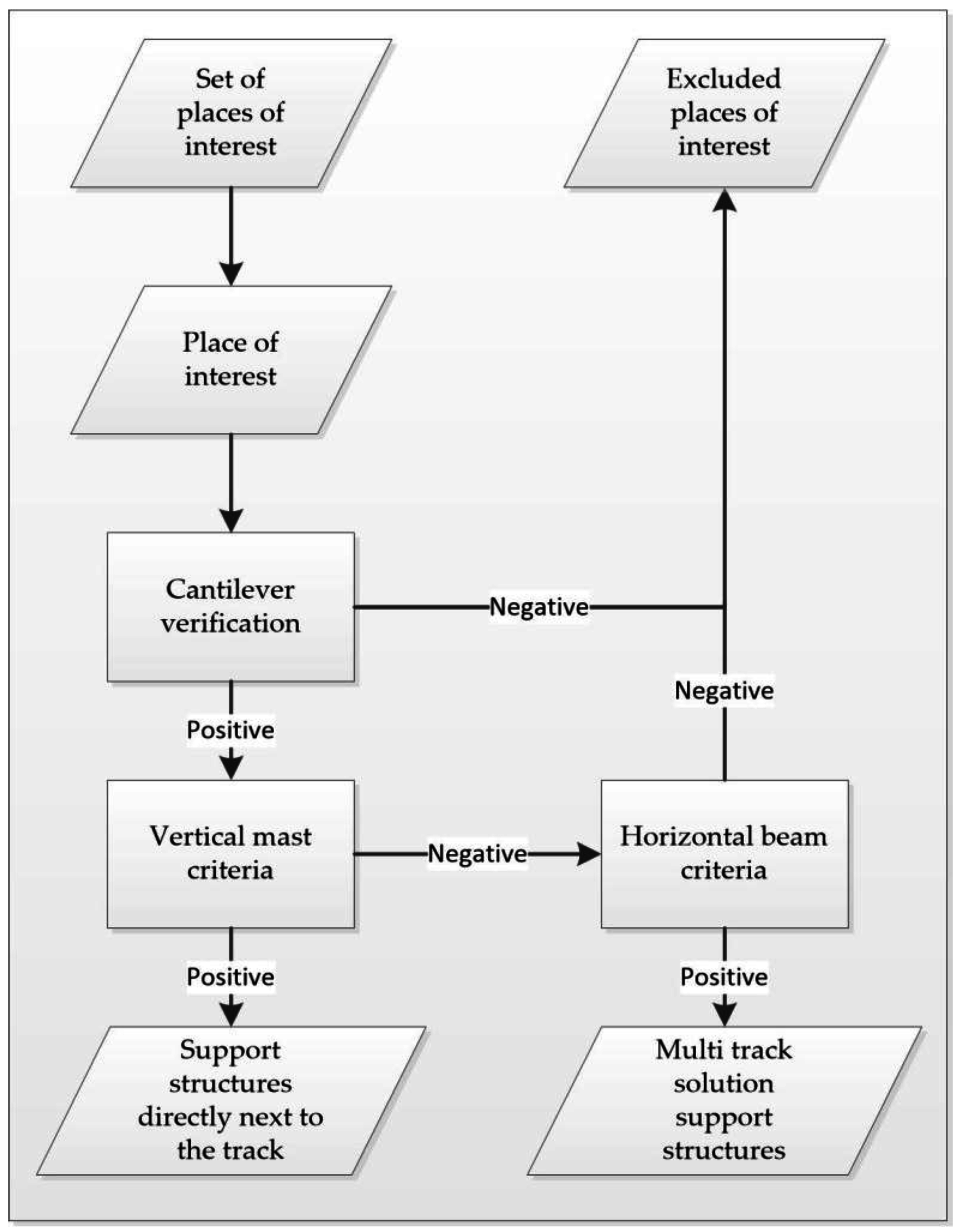
3.2.3. Support Structure Verification and Classification
The verification process has a couple of consecutive steps. The simplified algorithm structure is presented in
Figure 9.
(i) Cantilever Criteria
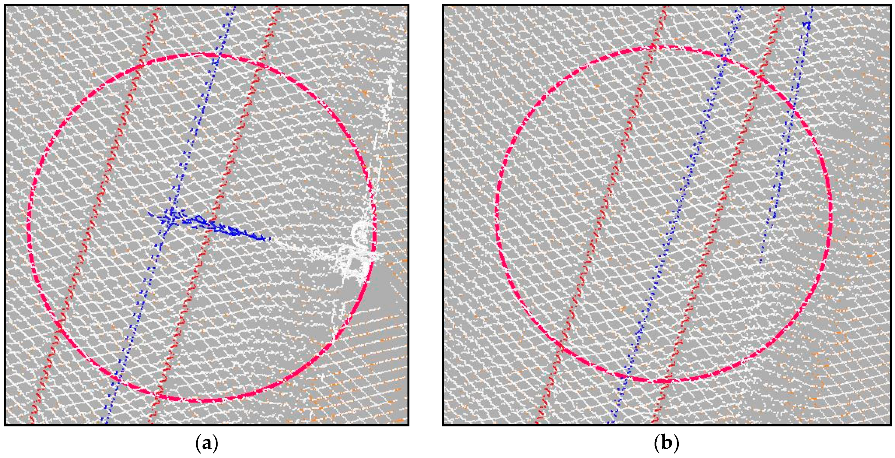
A higher point density above the track can indicate not only the presence of cantilevers (
Figure 10a), but also the joining of an additional track on turnouts/crossings (
Figure 10b), double catenary wires at the ends of tensioning sections or vegetation growing too close to the catenary wires. Depending on the object causing the increase of point density, the points registered above the track projected on a horizontal plane will form a different pattern. As cantilevers are positioned almost perpendicular to the track, the pattern will resemble a cross. In other cases, there might be two lines meeting at an acute angle, turnouts, section tensioning ending, or the shapeless formation of points, vegetation.
To rule out false positives, each place of interest must be considered separately. Firstly, a set of points that should contain a catenary, together with the object causing the density increase, is selected based on the distance to the considered location. If a cantilever is present in a selected set of points, far more points should be registered on it than on catenary wires. All points are then projected onto a horizontal plane; the elevation coordinate is taken out of the equation; and then, a line is fitted to this set of points to determine the presence of cantilevers.
The RANSAC algorithm [
42] has been used, as it performs well in very noisy environments. Through the years, this algorithm has been implemented in many point cloud-processing algorithms, including primitive shape detection [
3] and roof detection [
43]. RANSAC considers that the given data can be categorized into two sets, noise and model data. It then proceeds to fit the model to randomly-selected minimal sample data. The model that incorporates maximum data entities is chosen as the proper one. In the case of these calculations, cantilevers are the model (model distance r
1), and all other points are treated as noise.
If a determined line is almost perpendicular to the trajectory, a support structure can be verified; if not, the location is treated as a false positive. In the case of positive authentication, all model points are classified as the catenary system.
All verified places of interest are passed on for further categorization and support structure positioning.
(ii) Vertical Mast and Horizontal Beam Criteria
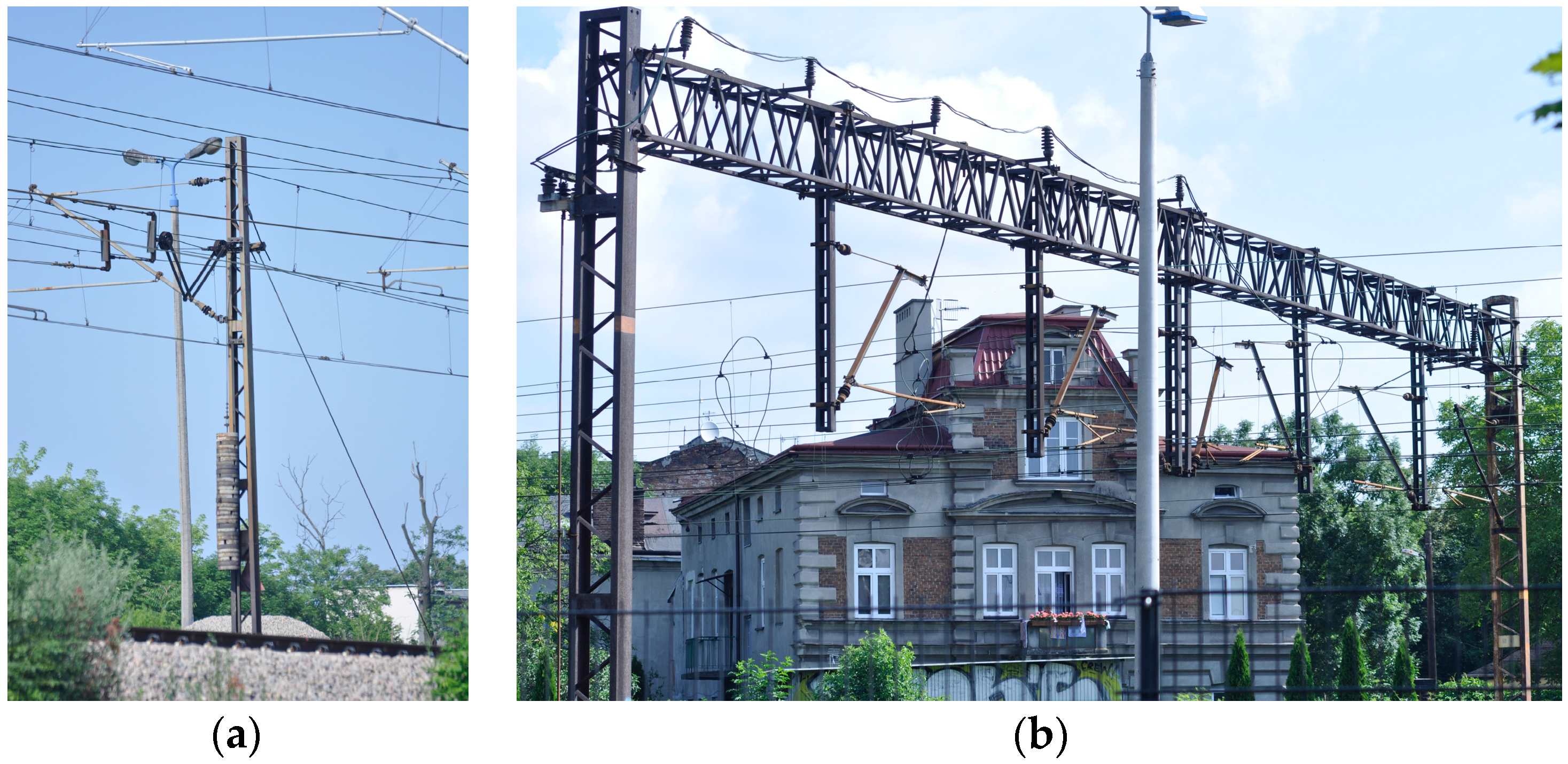
Detected support structures are divided into two categories, traction poles and portal structures. The first category includes all construction where masts are located directly next to the applicable track, both single and multi-track solutions. The second includes all remaining portal structures.
The division is performed based on localizing a mast in close proximity to the measured track. Firstly, a set of points is selected, limited horizontally to s
h along the trajectory and ±s
z from the trajectory key point vertically. The area to the right and to the left side of the track is checked separately. There are four possible outcomes of said procedure.
Number of points to the right exceeds set threshold and to the left does not.
Number of points to the left exceeds set threshold and to the right does not.
Number of points to the right and to the left exceed set threshold.
Number of points to the right and to the left do not exceed set threshold.
The two first cases suggest the possibility of a mast next to the rail track. The third shows objects on both sides of the track, and the fourth implies a portal structure. As there are a great deal of different objects that might identify the existence of a significant number of points in the aforementioned subset, each case needs to be verified.
Case 1 and 2: A RANSAC algorithm is used to fit a line into a point selected by set horizontal and vertical limitations (model distance r2). If the fitted line is almost vertical, the intersection of it and the terrain is calculated as the position of the traction pole. If the fitted line is not vertical, the place of interest is moved and is to be verified by the process for Case Scenario 4.
Case 3: To find a pole in this case, its separation from other objects is taken into consideration. Thus, on both sides, the RANSAC algorithm is used twice: once with a threshold distance r2 and also with a threshold distance of 2r2. Firstly, the vertical requirement is checked, and then, the number of model points between the 1st and 2nd set is compared. The pole is detected in the place where the difference between the number of set points in between iterations is smaller. The pole coordinates are calculated as in Cases 1 and 2. If none of the objects are established as vertical, the place of interest is moved and is then verified by the process for Case Scenario 4.
Case 4: There are no vertical pole-like objects next to the track. Therefore, either the support structure was verified incorrectly or this is a multi-track solution (portal structure) where the cantilever is secured to the structural beam above it. Again, RANSAC (threshold distance r3) is used to fit the line to points above the catenary. If the line is perpendicular to the track and contains more points than the set threshold portal structure, it is verified, and its position trajectory key point is confirmed. In other cases, the point of interest is deleted from the checked set.
In all of the above cases, upon support structure verification, all RANSAC model points are classified as a catenary system. The minimal point count thresholds are set manually, according to point density.
3.2.4. Data Classification Clarification
As the process of classification has been simplified, not all points registered on the sought after infrastructure were found, and therefore, not all classified points were assigned correctly. The process of classification has been divided into two separate operations. The first considers detected support structures (i), the second catenary wires (ii).
(i) Support Structures
To refine the classification of support structures, a modification of the DBSCAN clustering algorithm was used. The DBSCAN algorithm, as published in [
44], is used to perform data clustering of unorganized sets of data points. It can be applied to various sets of data, including point clouds [
45]. It groups together points according to their neighborhood and distance. The algorithm proposes an iterative clustering method, which considers three types of points, core points, border points and outliers. Both core points and border points belong to the group. To assign unclassified points to the group, the point has to be within a set distance to one of the core points. It becomes a core point if there are more than a set number of group points in its neighborhood; otherwise, it becomes a border point.
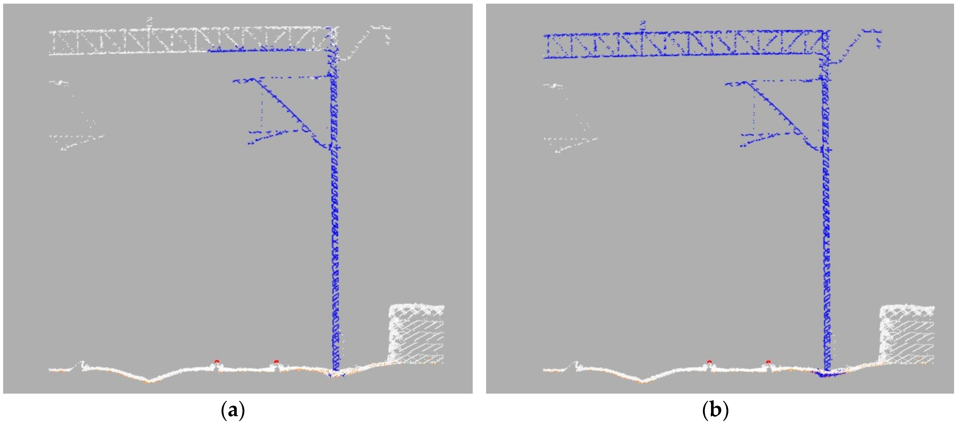
DBSCAN’s simple principles make it easy to adapt it to this study. The algorithm has been modified to not detect a group of points, but being provided a set of points, among which some have been assigned to a certain group, to detect points among unassigned, which belong to said group. It has then been applied to each detected support structure in two separate calculations. The first considers all points from the middle (dm) vertically-wise and up and the second from the middle vertically-wise and down to stop the classification process from spreading along low vegetation and ground points.
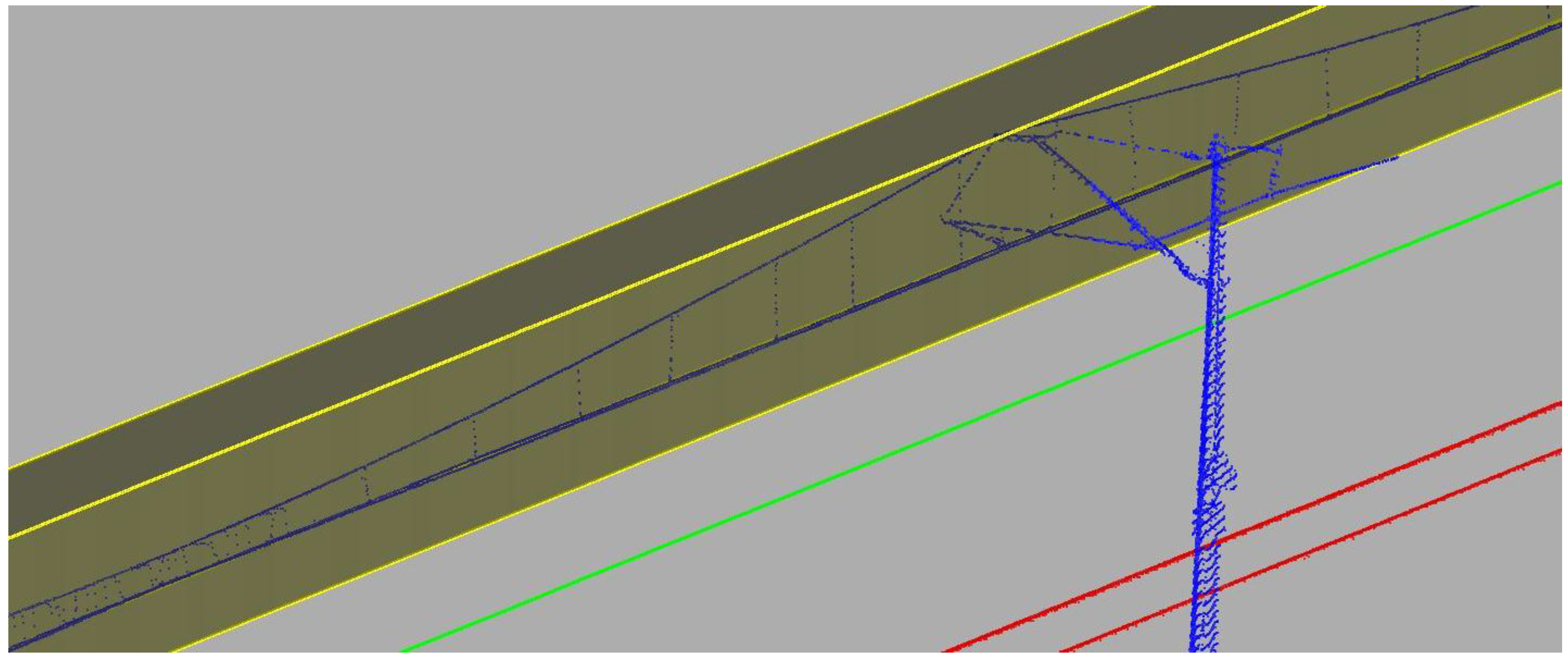
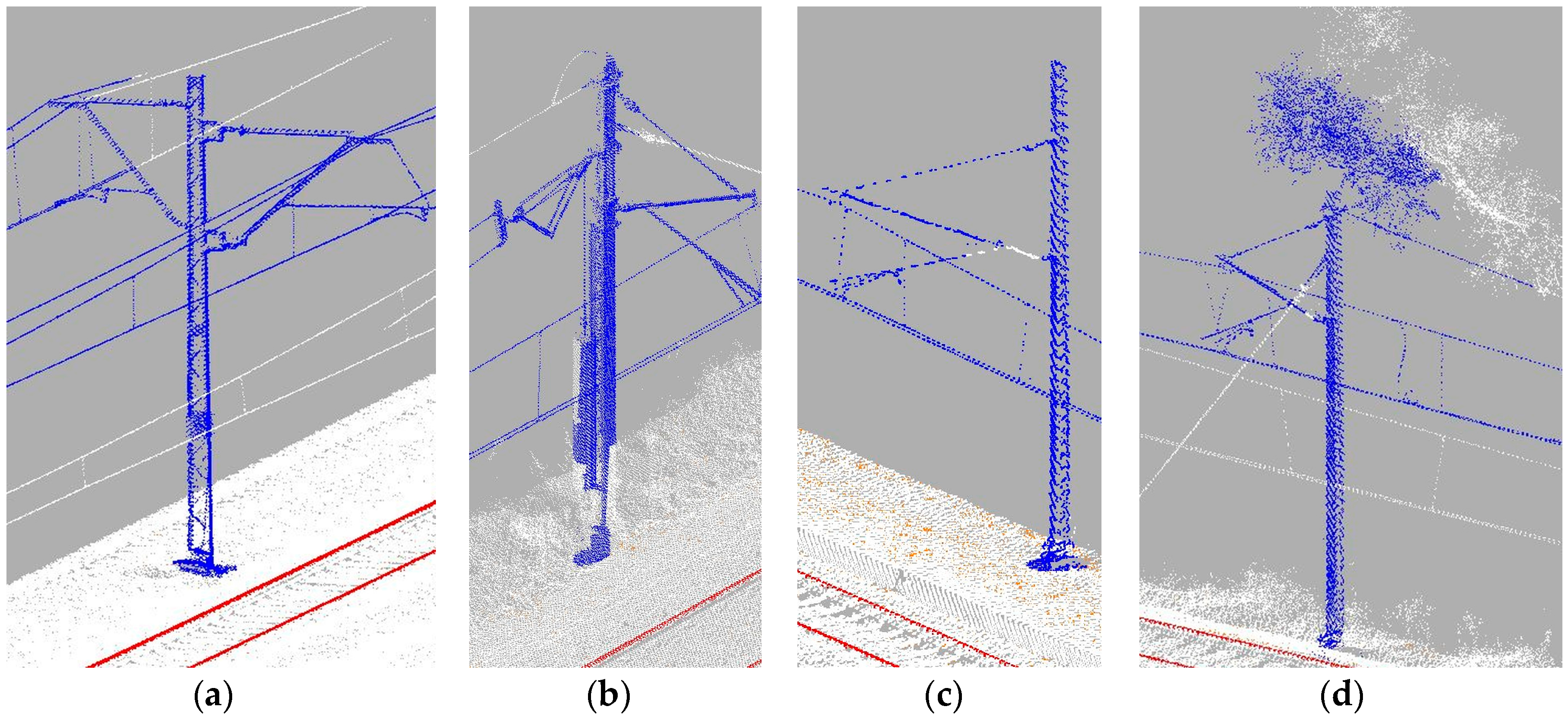
Figure 11 presents detected support structures before and after the modified DBSCAN processing. Both distance and neighborhood thresholds have to be set according to the available data. DBSCAN parameters maximal distance (dd) and neighborhood count (nc) have to be set manually according to point density.
(ii) Catenary Wires
The goal of this step is to find points that do not belong to the catenary, but, due to simplified classification procedures, were included in this class. This includes greenery growing too close to the track, isolated noise points or other objects that might come into contact with the catenary. That also might include incorrectly excluded support structures. Boundaries determined during the initial density check procedure are considered (
Section 3.2.2). In ideal circumstances, these boundaries would include only points registered on the catenary and, between the support structures, only the catenary cables. As the cables are being stretched, boundaries should linearly change between the consecutive sections.
To detect places of interest, the following procedure is implemented. Firstly, the whole analyzed railway line is divided into segments by all of the detected support structures. Then, the boundary diagonal is calculated for every section belonging to a considered segment. If, in between the consecutive sections, a discrepancy of the diagonal exceeds set threshold, c, then the region is evaluated again. There are two case scenarios where this can happen:
an unidentified object too close to the catenary system,
catenary cables heading towards tension poles or other tracks.
Determining each case is relatively easy. The cables heading towards tension poles or other tracks cause only one significant discrepancy between consecutive sections. In other case scenarios, there have to be at least two significant discrepancies nearby. In the event of the first case scenario, cables departing from the main thread, said cables are located by the RANSAC algorithm (model distance r4). As it might be a set of cables instead of one thread, the search is conducted in sets of points projected onto a horizontal plane. The RANSAC model points are again classified as the catenary system. The second case scenario, for all of the sections where a significant discrepancy occurs, a new boundary is calculated. New boundary vertices are determined by the intersection of lines fitted to nearby boundary vertices and said section plane. All points excluded from the boundary in the newly-evaluated section are moved to an unassigned class. Additionally, the set of all corrected sections for the whole analyzed rail line is written to a separate file as objects that might jeopardize rail safety.


