
Characterization of Ferroelectric Al0.7Sc0.3N Thin Film on Pt and Mo Electrodes


Abstract
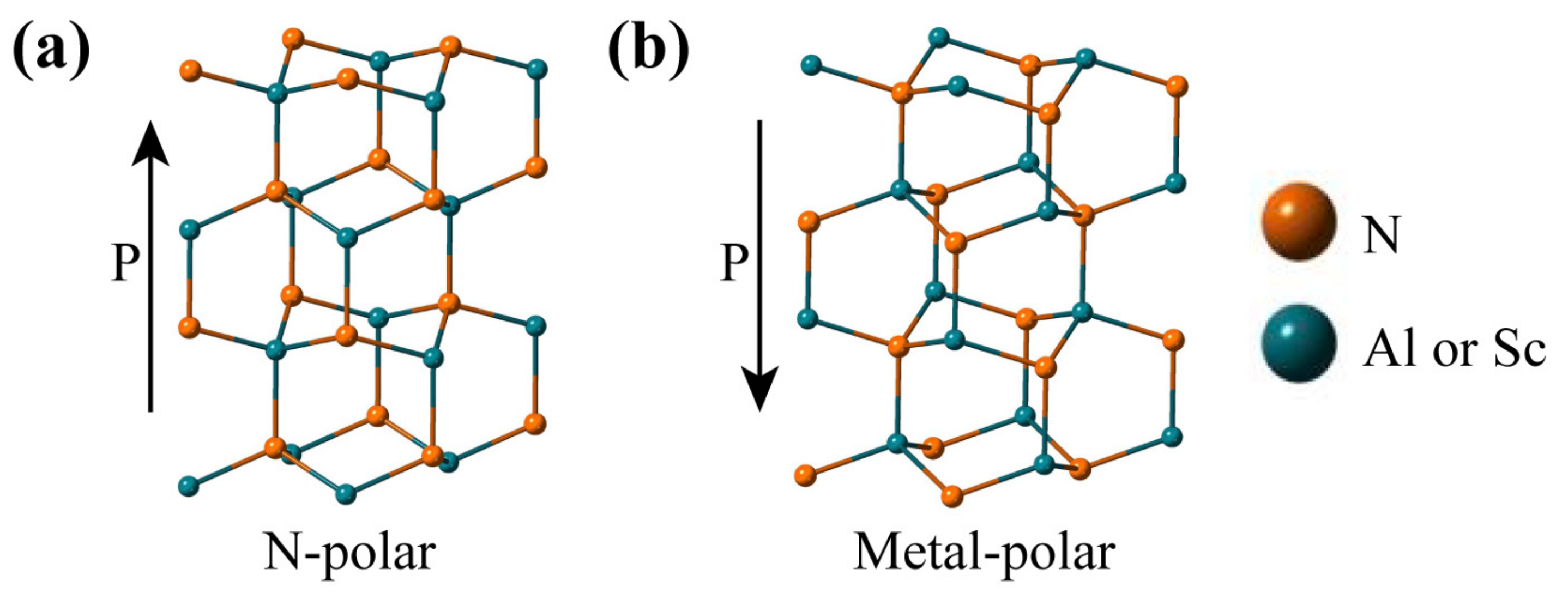
:1. Introduction
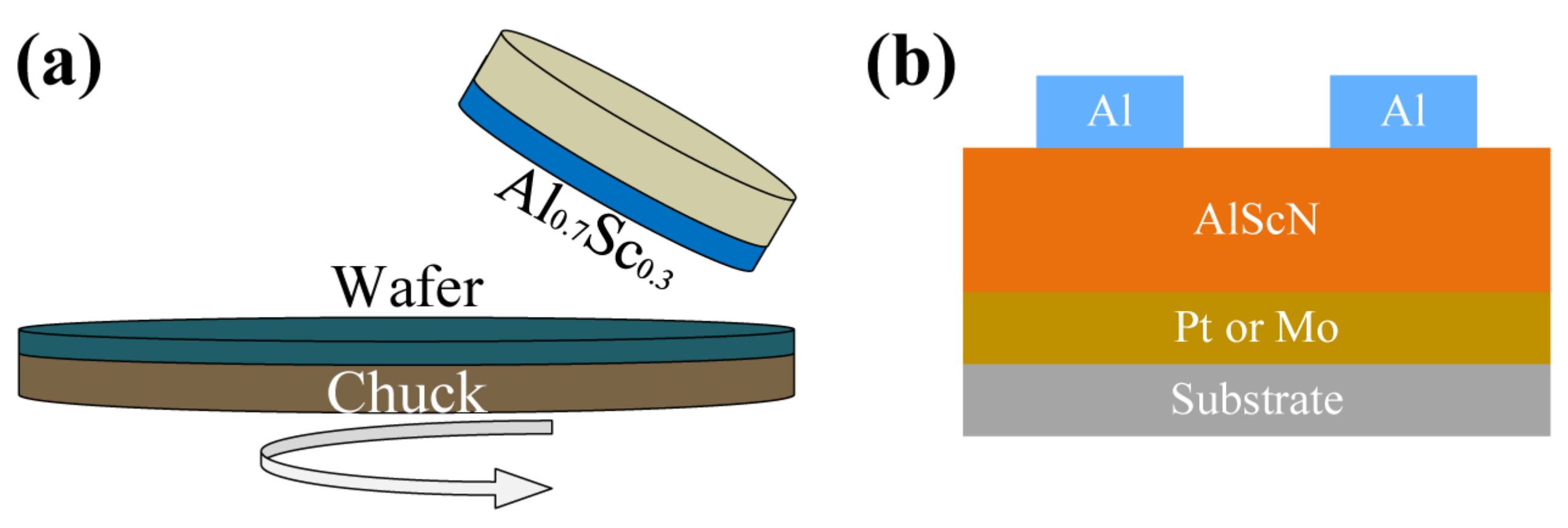
2. Fabrication and Experiment Setup
3. Results and Discussions
3.1. Film Quality Characterization
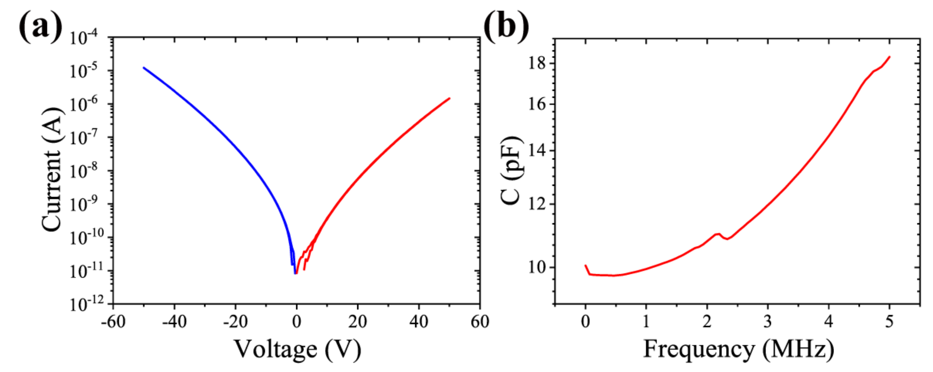
3.2. Dielectric Properties Measurement
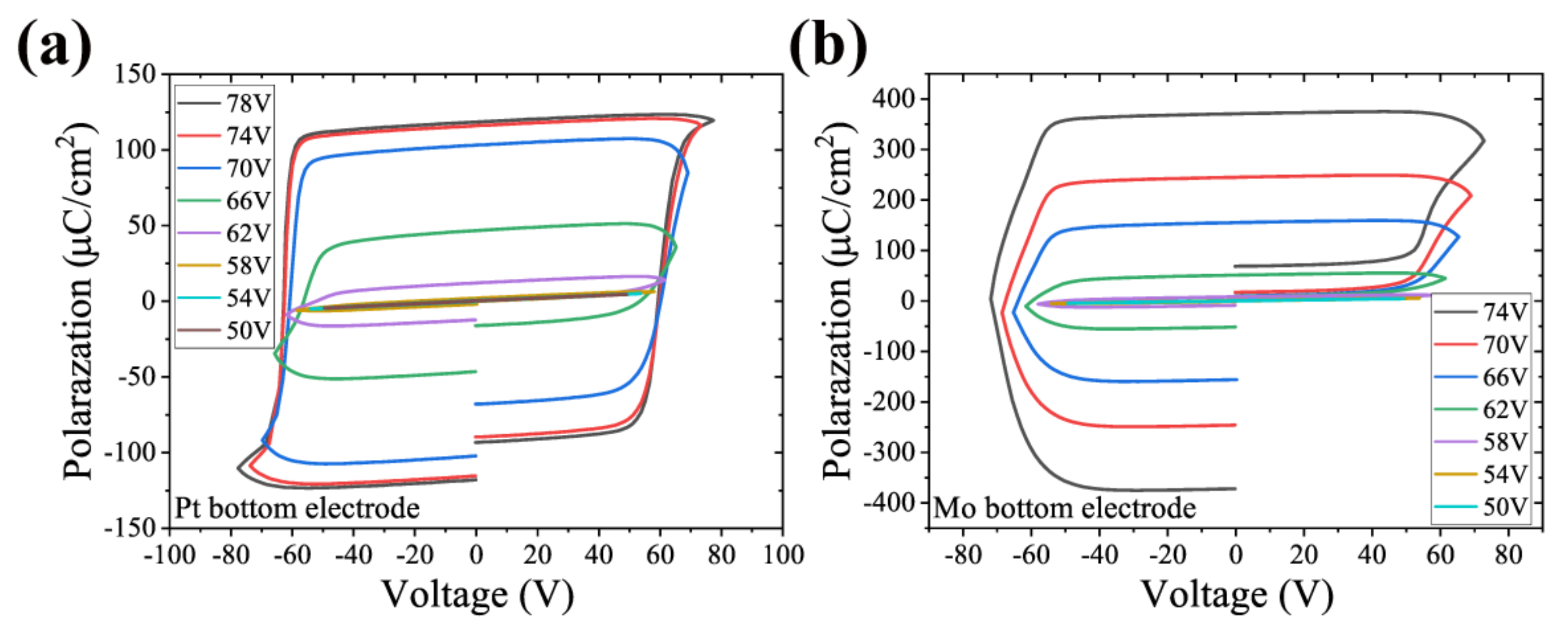
3.3. Effect of Different Electrodes on P-E Ferroelectric Hysteresis
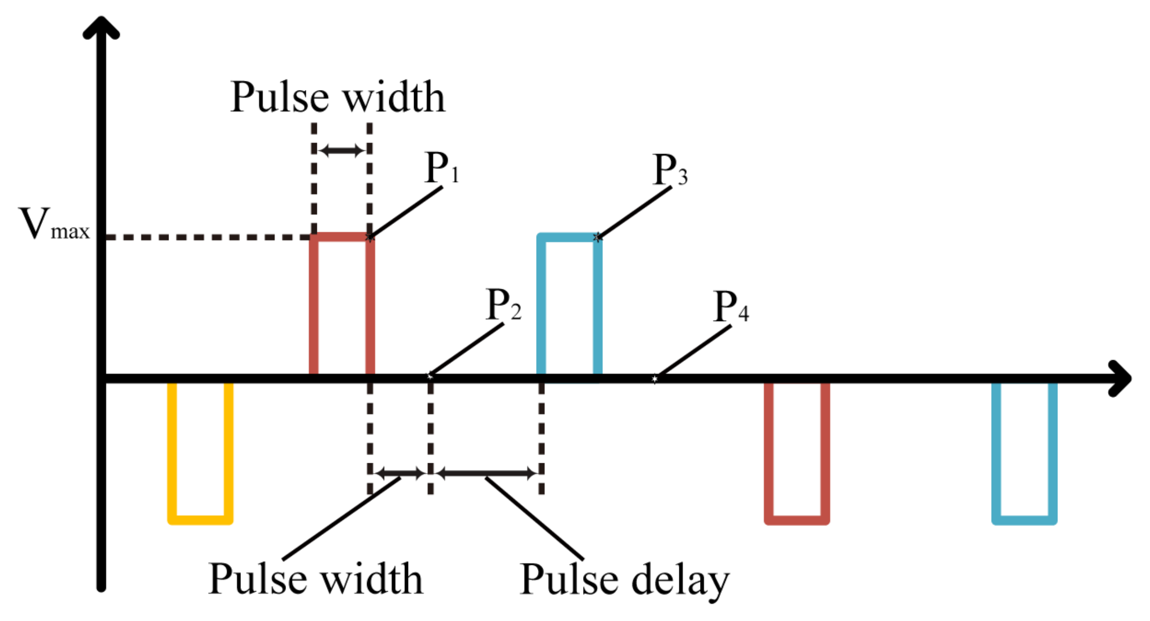
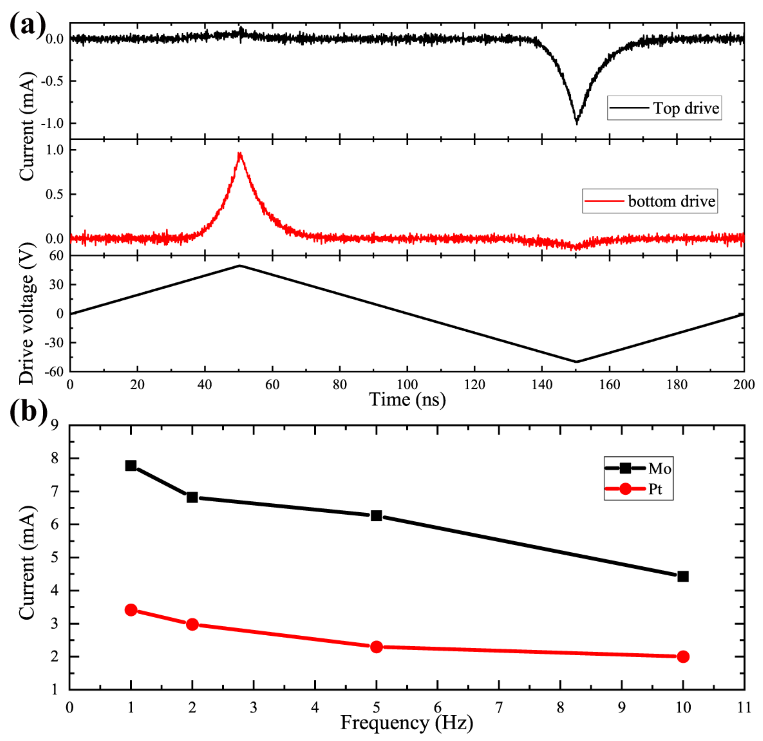
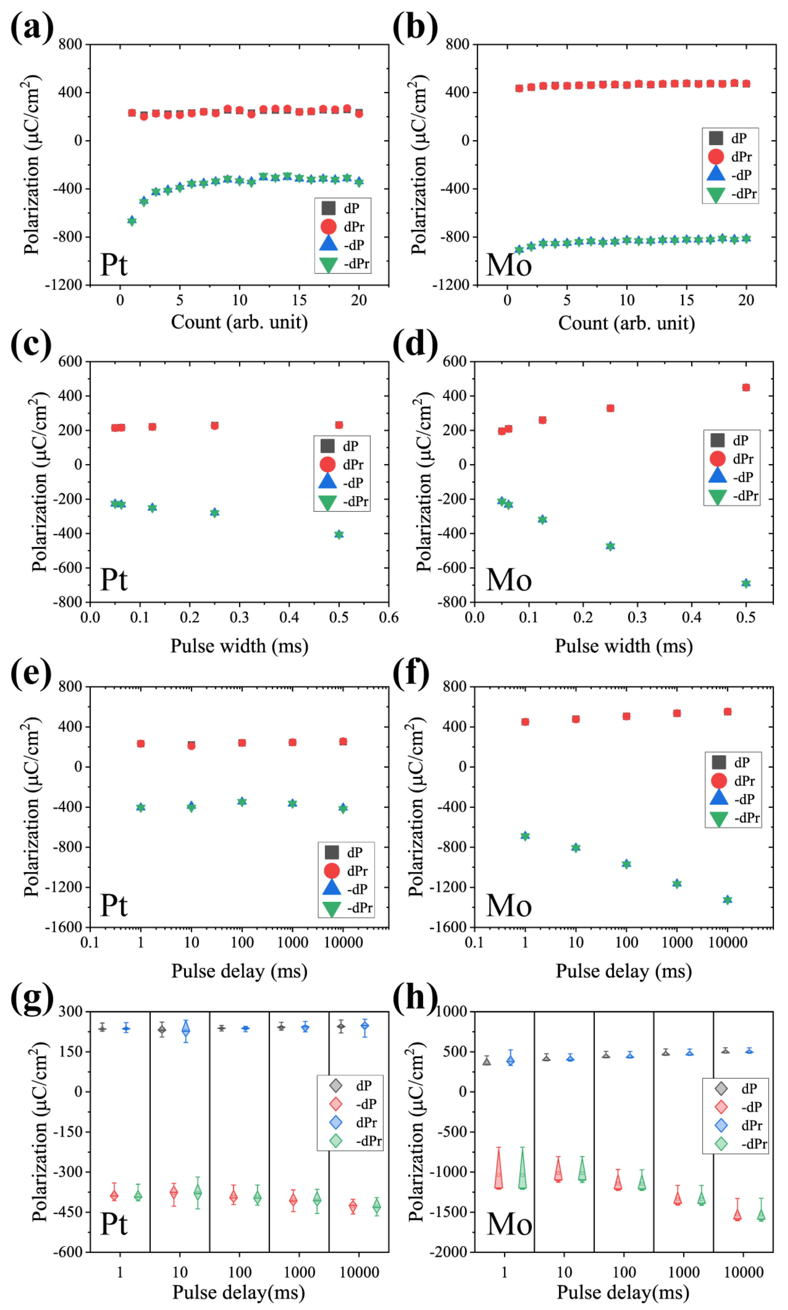
3.4. PUND Test to Obtain the Remanent Polarization
4. Conclusions
Author Contributions
Funding
Data Availability Statement
Acknowledgments
Conflicts of Interest
References
- Li, S.; Yilin, W.; Yang, M.; Miao, J.; Lin, K.; Li, Q.; Chen, X.; Deng, J.; Xing, X. Ferroelectric thin films: Performance modulation and application. Mater. Adv. 2022, 3, 5735–5752. [Google Scholar] [CrossRef]
- Martin, L.W.; Rappe, A.M. Thin-film ferroelectric materials and their applications. Nat. Rev. Mater. 2017, 2, 16087. [Google Scholar] [CrossRef]
- Setter, N.; Damjanovic, D.; Eng, L.; Fox, G.; Gevorgian, S.; Hong, S.; Kingon, A.; Kohlstedt, H.; Park, N.Y.; Stephenson, G.B.; et al. Ferroelectric thin films: Review of materials, properties, and applications. J. Appl. Phys. 2006, 100, 051606. [Google Scholar] [CrossRef]
- Wang, D.; Zheng, J.; Musavigharavi, P.; Zhu, W.; Foucher, A.C.; Trolier-McKinstry, S.E.; Stach, E.A.; Olsson, R.H. Ferroelectric Switching in Sub-20 nm Aluminum Scandium Nitride Thin Films. IEEE Electron. Device Lett. 2020, 41, 1774–1777. [Google Scholar] [CrossRef]
- Schenk, T.; Mueller, S. A New Generation of Memory Devices Enabled by Ferroelectric Hafnia and Zirconia. In Proceedings of the International Symposium on Applications of Ferroelectrics (ISAF), Sydney, Australia, 16–21 May 2021; pp. 1–11. [Google Scholar] [CrossRef]
- Kreutzer, T.N.; Fichtner, S.; Wagner, B.; Lofink, F. A double-layer MEMS actuator based on ferroelectric polarization inversion in AlScN. In Proceedings of the International Symposium on Applications of Ferroelectrics (ISAF), Sydney, Australia, 16–21 May 2021; pp. 1–3. [Google Scholar] [CrossRef]
- Wang, J.; Park, M.; Mertin, S.; Pensala, T.; Ayazi, F.; Ansari, A. A Film Bulk Acoustic Resonator Based on Ferroelectric Aluminum Scandium Nitride Films. J. Microelectromech. Syst. 2020, 29, 741–747. [Google Scholar] [CrossRef]
- Fichtner, S.; Wolff, N.; Lofink, F.; Kienle, L.; Wagner, B. AlScN: A III-V semiconductor based ferroelectric. J. Appl. Phys. 2019, 125, 114103. [Google Scholar] [CrossRef]
- Shao, S.; Luo, Z.; Lu, Y.; Mazzalai, A.; Tosi, C.; Wu, T. High Quality Co-Sputtering AlScN Thin Films for Piezoelectric Lamb-Wave Resonators. J. Microelectromech. Syst. 2022, 31, 328–337. [Google Scholar] [CrossRef]
- Shao, S.; Luo, Z.; Lu, Y.; Mazzalai, A.; Tosi, C.; Wu, T. Low Loss Al0.7Sc0.3N Thin Film Acoustic Delay Lines. IEEE Electron. Device Lett. 2022, 43, 647–650. [Google Scholar] [CrossRef]
- Olsson, R.H.; Tang, Z.; D’Agati, M. Doping of Aluminum Nitride and the Impact on Thin Film Piezoelectric and Ferroelectric Device Performance. In Proceedings of the Custom Integrated Circuits Conference (CICC), Boston, MA, USA, 22–25 March 2020; pp. 1–6. [Google Scholar] [CrossRef]
- Shao, S.; Luo, Z.; Wu, T. High Figure-of-Merit Lamb Wave Resonators Based on Al0.7Sc0.3N Thin Film. IEEE Electron. Device Lett. 2021, 42, 1378–1381. [Google Scholar] [CrossRef]
- Wang, J.; Park, M.; Mertin, S.; Pensala, T.; Ayazi, F.; Ansari, A. A High-$k_t⌃2$ Switchable Ferroelectric Al0.7Sc0.3N Film Bulk Acoustic Resonator. In Proceedings of the Joint Conference of the IEEE International Frequency Control Symposium and International Symposium on Applications of Ferroelectrics (IFCS-ISAF), Keystone, CO, USA, 19–23 July 2020; pp. 1–3. [Google Scholar] [CrossRef]
- Pirro, M.; Herrera, B.; Assylbekova, M.; Giribaldi, G.; Colombo, L.; Rinaldi, M. Characterization of Dielectric and Piezoelectric Properties of Ferroelectric AlScN Thin Films. In Proceedings of the 34th International Conference on Micro Electro Mechanical Systems (MEMS), Gainesville, FL, USA, 25–29 January 2021; pp. 646–649. [Google Scholar] [CrossRef]
- Luo, Z.; Shao, S.; Wu, T. Al0.78Sc0.22N Lamb Wave Contour Mode Resonators. IEEE Trans. Ultrason. Ferroelectr. Freq. Control. 2021, 1. [Google Scholar] [CrossRef] [PubMed]
- Fichtner, S.; Lofink, F.; Wagner, B.; Schönweger, G.; Kreutzer, T.N.; Petraru, A.; Kohlstedt, H. Ferroelectricity in AlScN: Switching, Imprint and sub-150 nm Films. In Proceedings of the Joint Conference of the IEEE International Frequency Control Symposium and International Symposium on Applications of Ferroelectrics (IFCS-ISAF), Keystone, CO, USA, 19–23 July 2020; pp. 1–4. [Google Scholar] [CrossRef]
- Pirro, M.; Zhao, X.; Herrera, B.; Simeoni, P.; Rinaldi, M. Effect of Substrate-RF on Sub-200 nm Al0.7Sc0.3N Thin Films. Micromachines 2022, 13, 877. [Google Scholar] [CrossRef] [PubMed]
- Yasuoka, S.; Shimizu, T.; Tateyama, A.; Uehara, M.; Yamada, H.; Akiyama, M.; Hiranaga, Y.; Cho, Y.; Funakubo, H. Effects of deposition conditions on the ferroelectric properties of (Al1-x Scx)N thin films. J. Appl. Phys. 2020, 128, 114103. [Google Scholar] [CrossRef]
- Rabe, K.M.; Dawber, M.; Lichtensteiger, C.; Ahn, C.H.; Triscone, J.M. Modern Physics of Ferroelectrics:Essential Background. In Physics of Ferroelectrics: A Modern Perspective; Topics in Applied Physics; Springer: Berlin/Heidelberg, Germany, 2007; pp. 1–30. [Google Scholar] [CrossRef]
- Wang, D.; Zheng, J.; Tang, Z.; D’Agati, M.; Gharavi, P.S.M.; Liu, X.; Jariwala, D.; Stach, E.A.; Olsson, R.H.; Roebisch, V.; et al. Ferroelectric C-Axis Textured Aluminum Scandium Nitride Thin Films of 100 nm Thickness. In Proceedings of the Joint Conference of the IEEE International Frequency Control Symposium and International Symposium on Applications of Ferroelectrics (IFCS-ISAF), Keystone, CO, USA, 19–23 July 2020; pp. 1–4. [Google Scholar] [CrossRef]
- Schönweger, G.; Petraru, A.; Islam, M.R.; Wolff, N.; Haas, B.; Hammud, A.; Koch, C.; Kienle, L.; Kohlstedt, H.; Fichtner, S. From Fully Strained to Relaxed: Epitaxial Ferroelectric Al1-xScxN for III-N Technology. Adv. Funct. Mater. 2022, 32, 2109632. Available online: https://onlinelibrary.wiley.com/doi/pdf/10.1002/adfm.202109632 (accessed on 12 February 2022). [CrossRef]
- Giribaldi, G.; Pirro, M.; Soukup, B.H.; Assylbekova, M.; Colombo, L.; Rinaldi, M. Compensation of Contact Nature-Dependent Asymmetry in The Leakage Current of Ferroelectric ScxAl1-x N Thin-Film Capacitors. In Proceedings of the 34th International Conference on Micro Electro Mechanical Systems (MEMS), Gainesville, FL, USA, 25–29 January 2021; pp. 650–653. [Google Scholar] [CrossRef]


Publisher’s Note: MDPI stays neutral with regard to jurisdictional claims in published maps and institutional affiliations. |
© 2022 by the authors. Licensee MDPI, Basel, Switzerland. This article is an open access article distributed under the terms and conditions of the Creative Commons Attribution (CC BY) license (https://creativecommons.org/licenses/by/4.0/).
Share and Cite
Nie, R.; Shao, S.; Luo, Z.; Kang, X.; Wu, T. Characterization of Ferroelectric Al0.7Sc0.3N Thin Film on Pt and Mo Electrodes. Micromachines 2022, 13, 1629. https://doi.org/10.3390/mi13101629
Nie R, Shao S, Luo Z, Kang X, Wu T. Characterization of Ferroelectric Al0.7Sc0.3N Thin Film on Pt and Mo Electrodes. Micromachines. 2022; 13(10):1629. https://doi.org/10.3390/mi13101629
Chicago/Turabian StyleNie, Ran, Shuai Shao, Zhifang Luo, Xiaoxu Kang, and Tao Wu. 2022. "Characterization of Ferroelectric Al0.7Sc0.3N Thin Film on Pt and Mo Electrodes" Micromachines 13, no. 10: 1629. https://doi.org/10.3390/mi13101629