1. Introduction
The microwell array has become an essential analysis tool for various biological and chemical applications [
1]. It is important to develop efficient fabrication methods for the microwell arrays, which can offer lower costs and simpler production methods [
1,
2,
3]. Particularly, PDMS (polydimethylsiloxane) microwell arrays have been employed in manipulating and culturing cells for studying the individual behavior of cells in a microenvironment. Due to the fact that PDMS can be easily fabricated by using soft-lithography techniques and because it possesses many advantageous properties such as optical transparency, a non-toxic nature, and biocompatibility, it is considered to be a good material for various biological experiments [
4,
5]. In the early stages of cell-to-cell interaction studies, Petri dishes were used to form cell-to-cell contact [
5]. In cell-to-cell studies, cells must be attached on the substrate, and glass is a good substrate for attaching cells because cells like hard surfaces [
6].
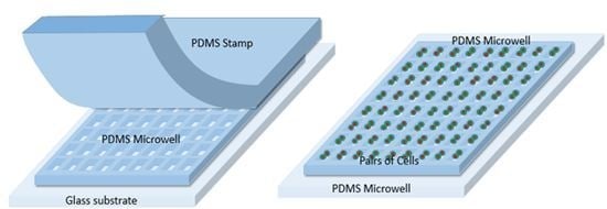
However, the ability to observe the cells that grow in the dish is limited due to the difficulty in growing and pairing cells for cell-to-cell study. Under conventional cell culture conditions, it is difficult to manipulate the cell position, spreading, shape and density. For a controlled cell culture environment, a PDMS stamping (or imprinting) method has been widely used since it can easily print micropatterns on a substrate of interest [
7,
8,
9]. This technology can offer a cell culture environment with well-controlled sizes, shapes, and positions on a substrate, thus providing a useful tool for cell studies. Gray et al. demonstrated a surface patterning method with cell-adhesive molecules using the PDMS stamping method for cell-to-cell contact studies [
10]. Despite its huge potential, the contact printing method by the PDMS stamp should be carefully controlled to avoid deformation of patterns limiting the robust fabrication of the device for testing. With a similar approach, Nelson et al. utilized agarose micropatterns based on the PDMS stamp method on a glass substrate for studying cell-to-cell contact [
11]. Its limitation is that, using this method, creating thick and high density patterns is challenging and, also, air bubbles can be easily trapped during the filling process of the agarose.
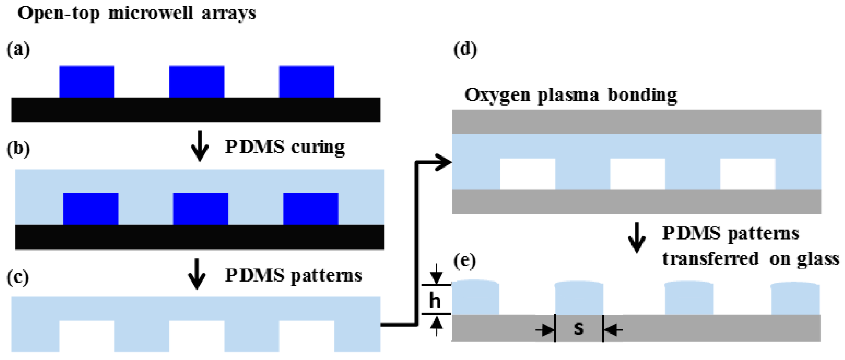
Here we demonstrate a simple fabrication method for creating the PDMS microwell arrays by transferring the patterns of the PDMS stamp onto a glass substrate. This method overcomes the limitations of the conventional PDMS imprinting method since it uses cured PDMS micropatterns only. Cured PDMS allows negligible volume shrink in microwell transfer because it is solid and the fact that no extra chemical treatment is necessary, just oxygen plasma treatment for the bonding during the transfer process, allows low-cost and quick fabrication of the devices. The handling of the device is easy and volume shrink is not as severe as when using agarose, without deformation of the pattern.
3. Result/Discussion
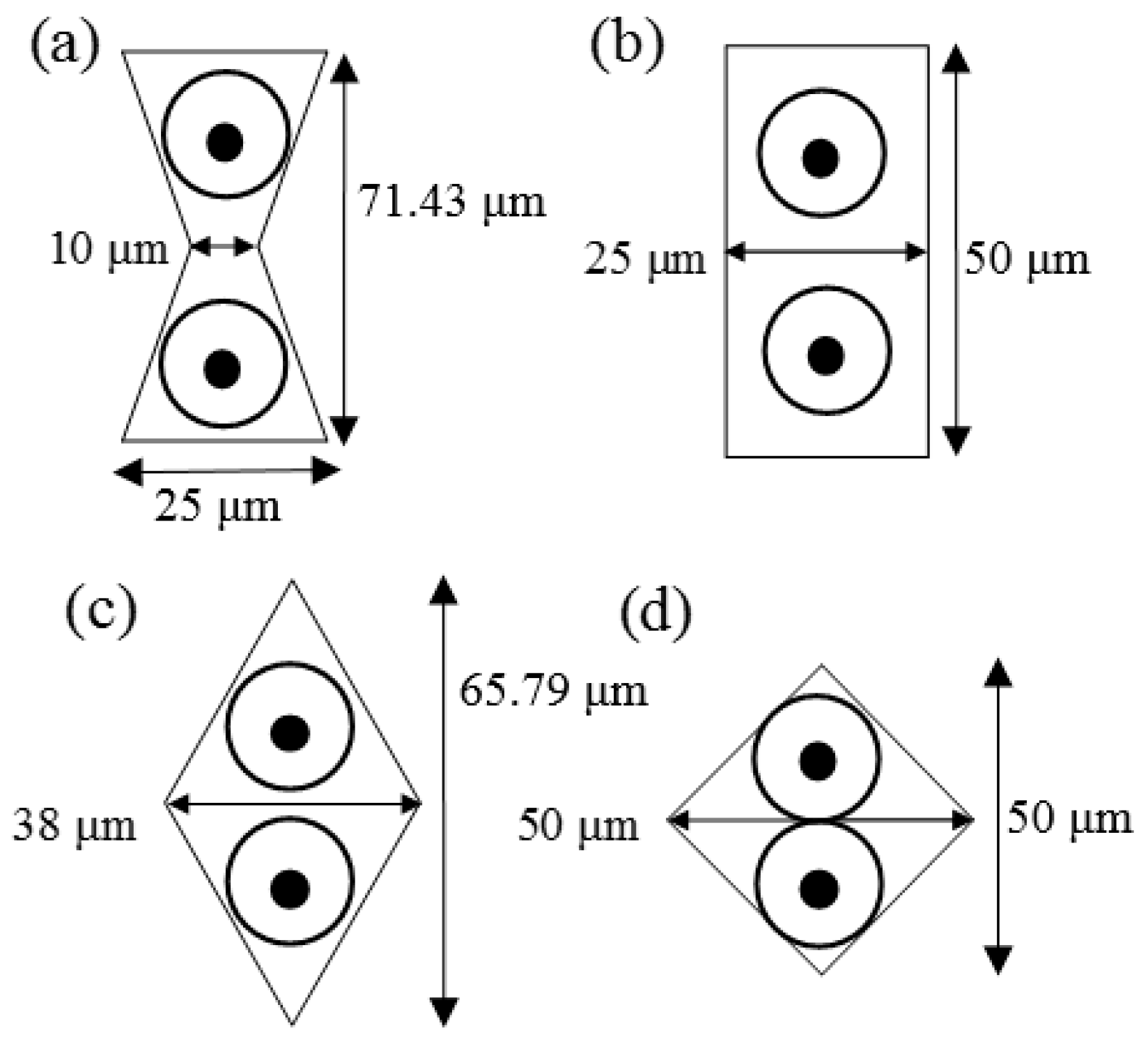
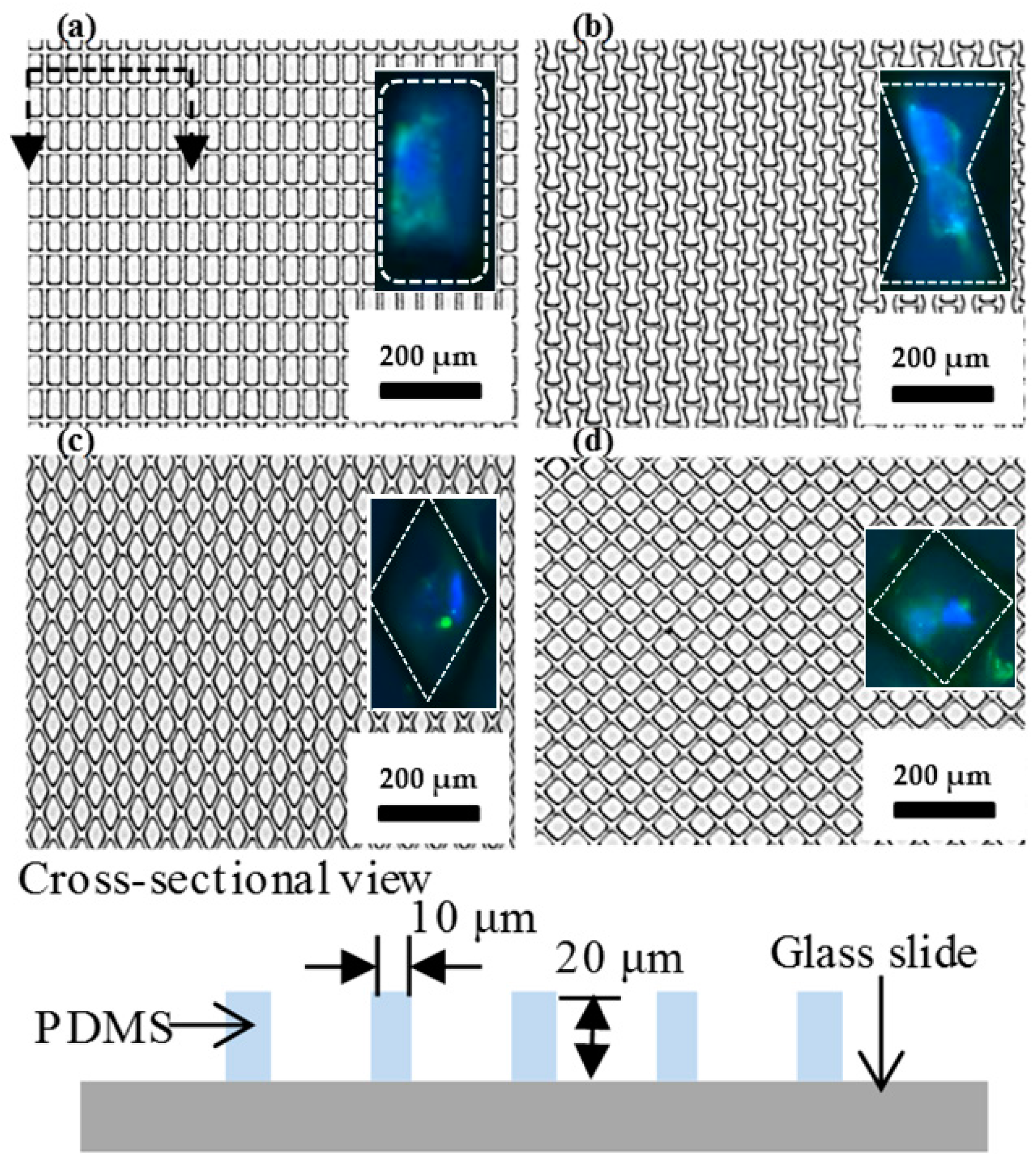
The image of four different shapes of microwell arrays transferred onto the glass substrate using the stamping method is shown in
Figure 3. One pair of cells is expected to be trapped in each of the microwells because the diameter of each cell is approximately 20 µm (the size of the well is 1250 µm
2, 625 µm
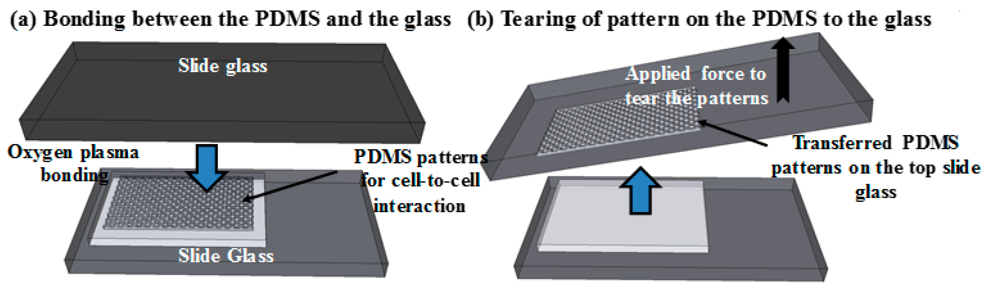
2 for each cell, so it is hard to trap more than two cells in each well). To transfer the microwell arrays from the PDMS stamp to the glass substrate, homemade tearing equipment was used to exert a force onto the top glass substrate. It is important to keep the peeling direction the same and while the force was continually applied, the stamp was peeled away as shown in
Figure 4. As a result, the microwell arrays on the PDMS stamp were fractured and torn along a mechanically weak corner and stable PDMS patterns were transferred from the PDMS stamp to the bottom glass substrate. Naturally, the PDMS microwell arrays were transferred onto the top glass surface due to the fact that the bonding force between the PDMS and the bottom glass is larger than that which is between the PDMS microstructure and the top glass.
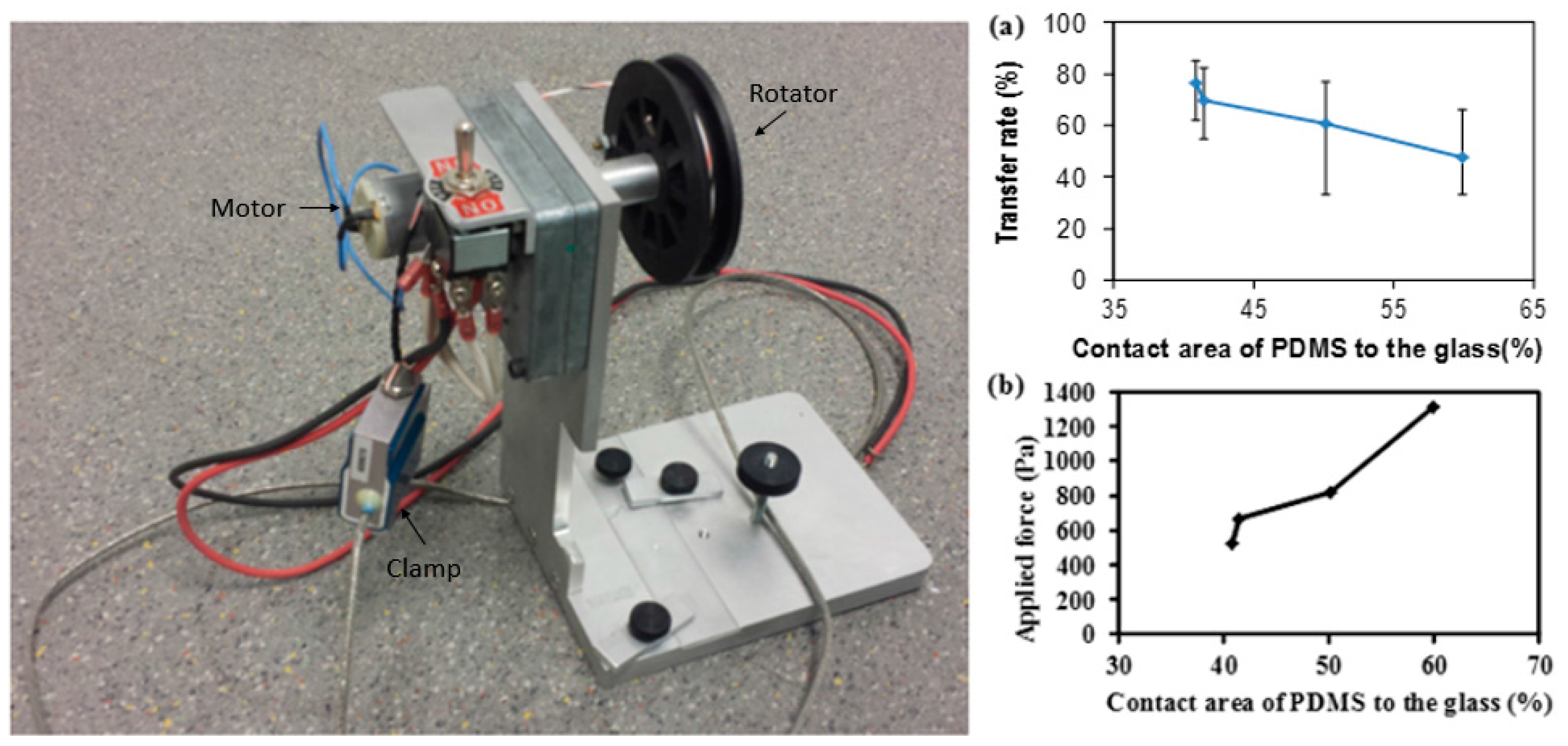
As shown in
Figure 5a, the transfer rate was measured as a function of the contact area of the PDMS stamp to the glass substrate using the stamp with a size of 5 mm × 5 mm. Error bars, which are the range between the maximum value and minimum value, were obtained through repeating the same experiment 10 times; the points indicate average values. The transfer rate is defined as the transferred number of patterns divided by the initial number of PDMS patterns. Since PDMS is a flexible material, the variation in the transfer rate is large. However, the average was above 50%, in the range of 40.82% to 59.91%, and the maximum was 76% at the low contact area of the PDMS to the glass. It shows that the patterns with a smaller contact area are more easily transferred since the crack resistance is low; thus, the crack starts more uniformly along the edge of the patterns at a mechanically unstable point. However, with increasing the contact area, the success rate was gradually decreased because a higher contact area leads to a stronger bonding force; this causes the PDMS stamp to be broken. As a result, more PDMS residue is left on the glass.
Moreover, the force required to lift the PDMS was measured as a function of the contact area and the result is shown in
Figure 5b. As the contact area is higher, a greater area is bonded to the glass, and therefore a stronger force is required to lift it from the PDMS which can break the PDMS stamp itself.
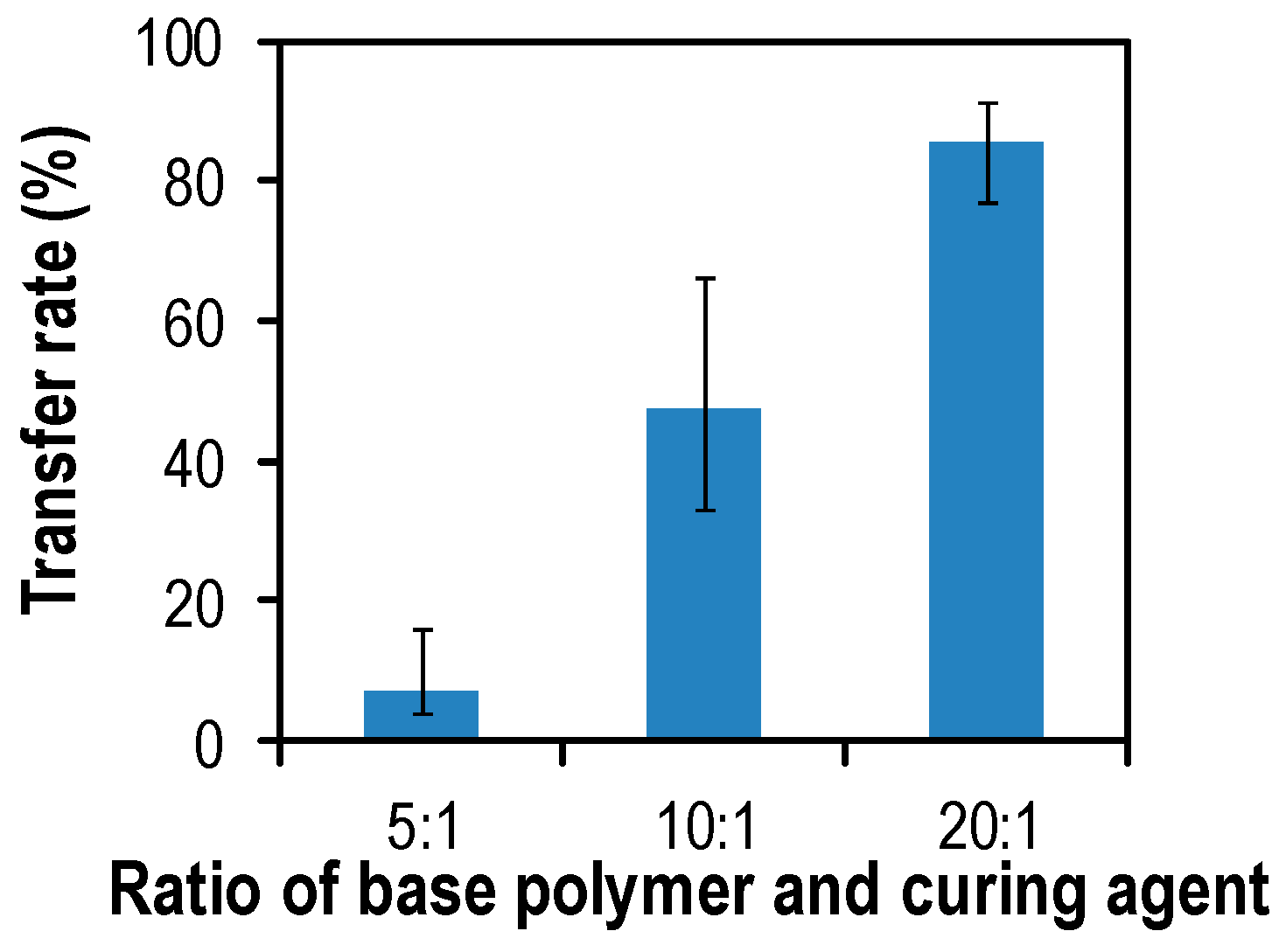
The stiffness of the PDMS stamp can be controlled by adjusting the mixing ratio between the pre-polymer and the curing agent. Higher ratios of the curing agent lead to the increased stiffness and hardness of the PDMS, mainly caused by an increase in cross-linking [
13]. The mixing ratios (pre-polymer:curing agent) varied from 5:1 to 20:1 and the transfer rate was measured as described previously.
Figure 6 shows the transfer rate as a function of the ratio between the pre-polymer and the curing agent. The error bars were obtained through repeating the same experiment 10 times. The contact area of the PDMS to the glass was fixed at 60%. Young’s modulus is defined by Hooke’s law
E = σ/ε, where σ is an applied stress and ε is a resultant strain [
14]. For the same strain, smaller strains indicate a higher stiffness of the material. At the low cross-linking density (20:1), the transfer rate was increased to 85% since the PDMS can be easily elongated, causing the crack at the corner of the patterns. Also, a smaller amount of curing agent in the PDMS has a better transfer rate must be caused by cohesion of the different polymer mixture. A smaller amount of curing agent must lead to lower cohesion of the polymer, which allows for easier breaking.
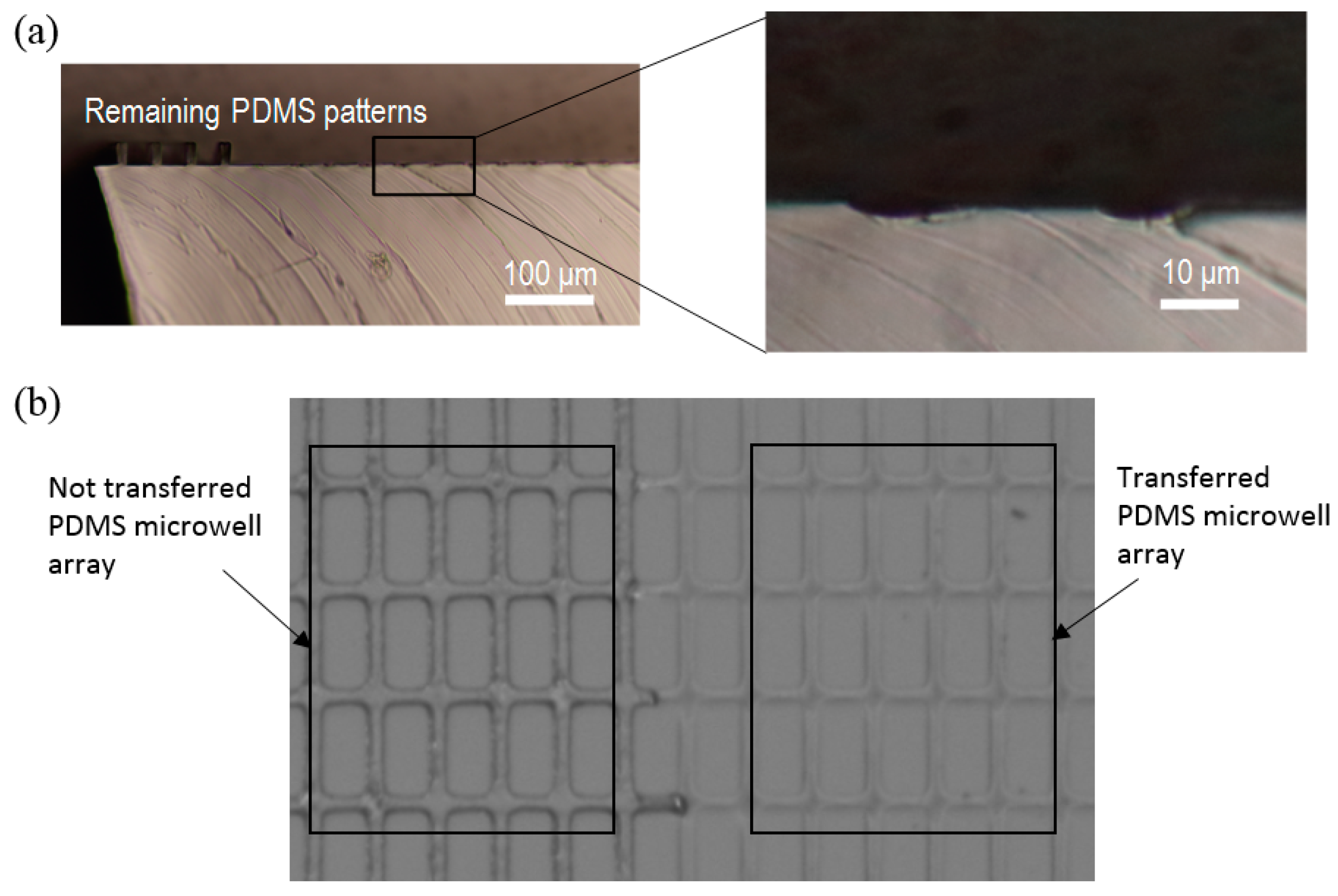
Next, we characterized the uniformity in the height of the microwells. As shown in
Figure 7, the PDMS patterns from the stamp after the transfer were cut, and the uniformity of the pattern height was observed. Uniformity of the transferred patterns from the PDMS stamp was measured by the following definition:
U = (
Hmax −
Hmin)/
Hmean × 100, where
Hmax is the maximum height,
Hmin is the minimum height and
Hmean is the average value of the height. A smaller
U value means more uniform patterns. The calculated uniformity of the patterns by this definition was 15.3%. Because of the flexible nature of PDMS, the height of the transferred PDMS microwells is not uniform but this is still enough for trapping cells in a cell-to-cell study since the height of the cell is 20 μm and the well height is close to this (usually higher than 20 μm).
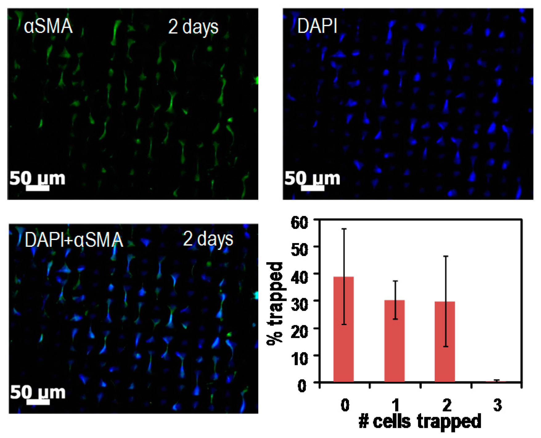
We observed the trapped cells on the bowtie microwell arrays as shown in
Figure 8. The capture efficiency for cell pairs was 29% on average. The cell-to-cell adhesion could be examined by staining cells using fluorescent dye, targeting various cadherin molecules that control BM-MSCs differentiation towards smooth muscle lineage. Specifically, we studied levels of Cad-11 (cadherin-11) and its effect on smooth muscle genes αSMA (α-smooth muscle actin), CNN-1 (calponin) and MYH11 (myosin heavy chain). Moreover, this tool is expected to be used in further studies of three or four neighboring cells in microwells; therefore, it may help to investigate biological questions such as whether cadherin-11 is a master regulator of BM-MSCs for smooth muscle differentiation.
Another possible application of the method is the fabrication of glass-PDMS-glass microfluidic devices. Since glass is a good substrate for studying cells, it is thus advisable to have a microfluidic device made by glass only, but it requires extensive work and expensive equipment. Therefore, instead of using only glass, a device made by top and bottom glass slides sandwiching a PDMS microfluidic channel layer (glass-PDMS-glass configuration) is easier and cheaper, and also is a good environment for microfluidic cell studies. For the fabrication of the glass-PDMS-glass configuration device, instead of transferring microwell arrays, we transfer the microfluidic channel pattern on a glass substrate and seal the channel with another glass substrate on top of the transferred microfluidic channel pattern. Proving the reliability of the proposed method in the glass-PDMS-glass configuration for studying cells in microfluidic systems requires good experimental results [
15].


