
Study on Dynamic Snap-Through and Nonlinear Vibrations of an Energy Harvester Based on an Asymmetric Bistable Composite Laminated Shell

Abstract
:1. Introduction
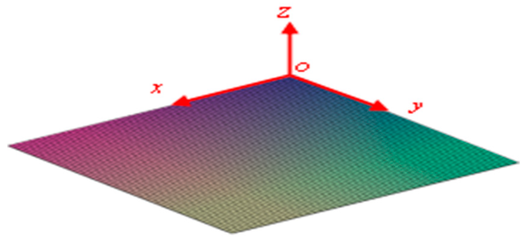
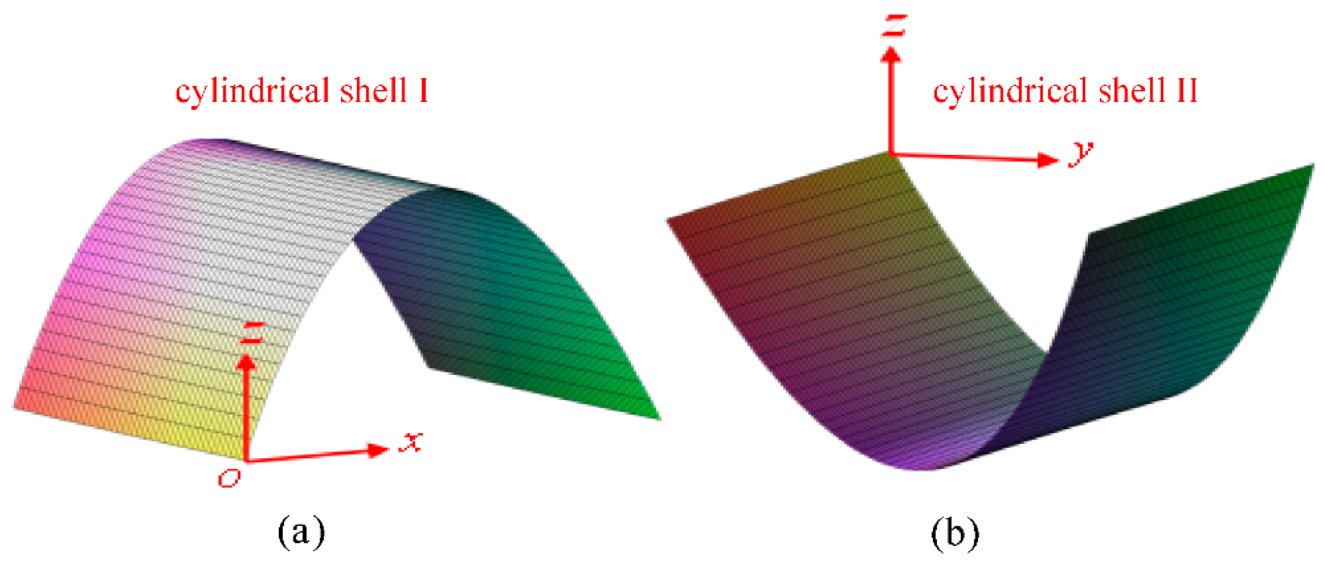
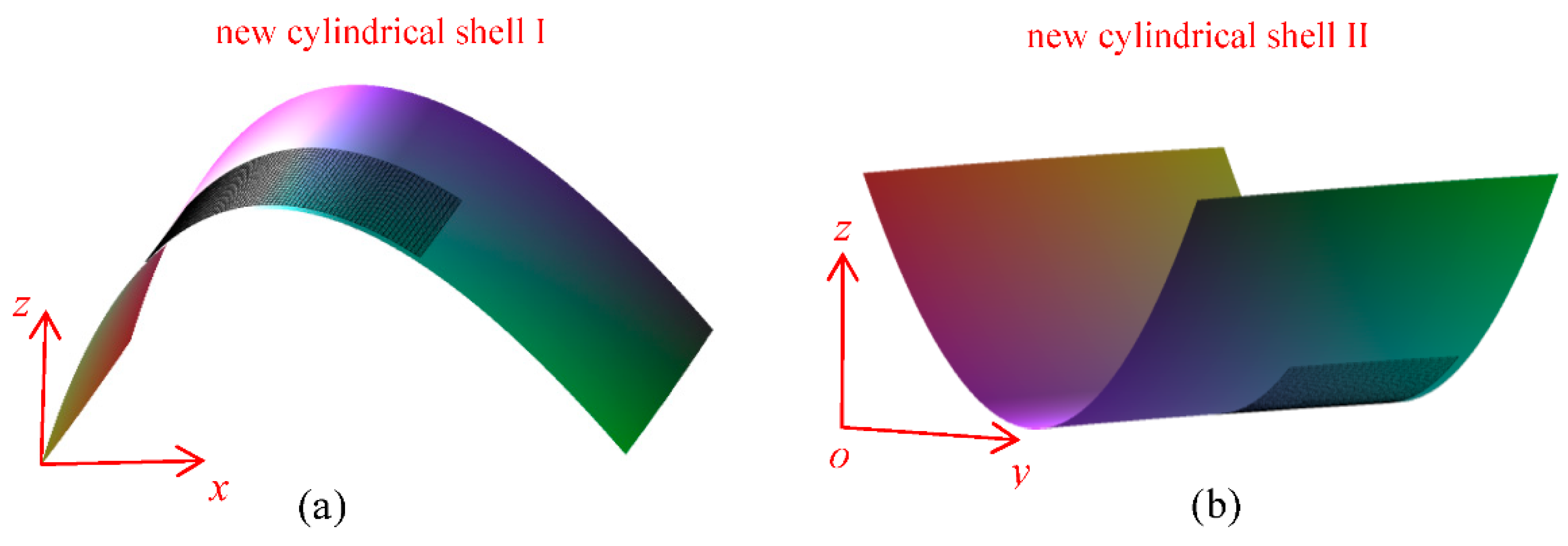
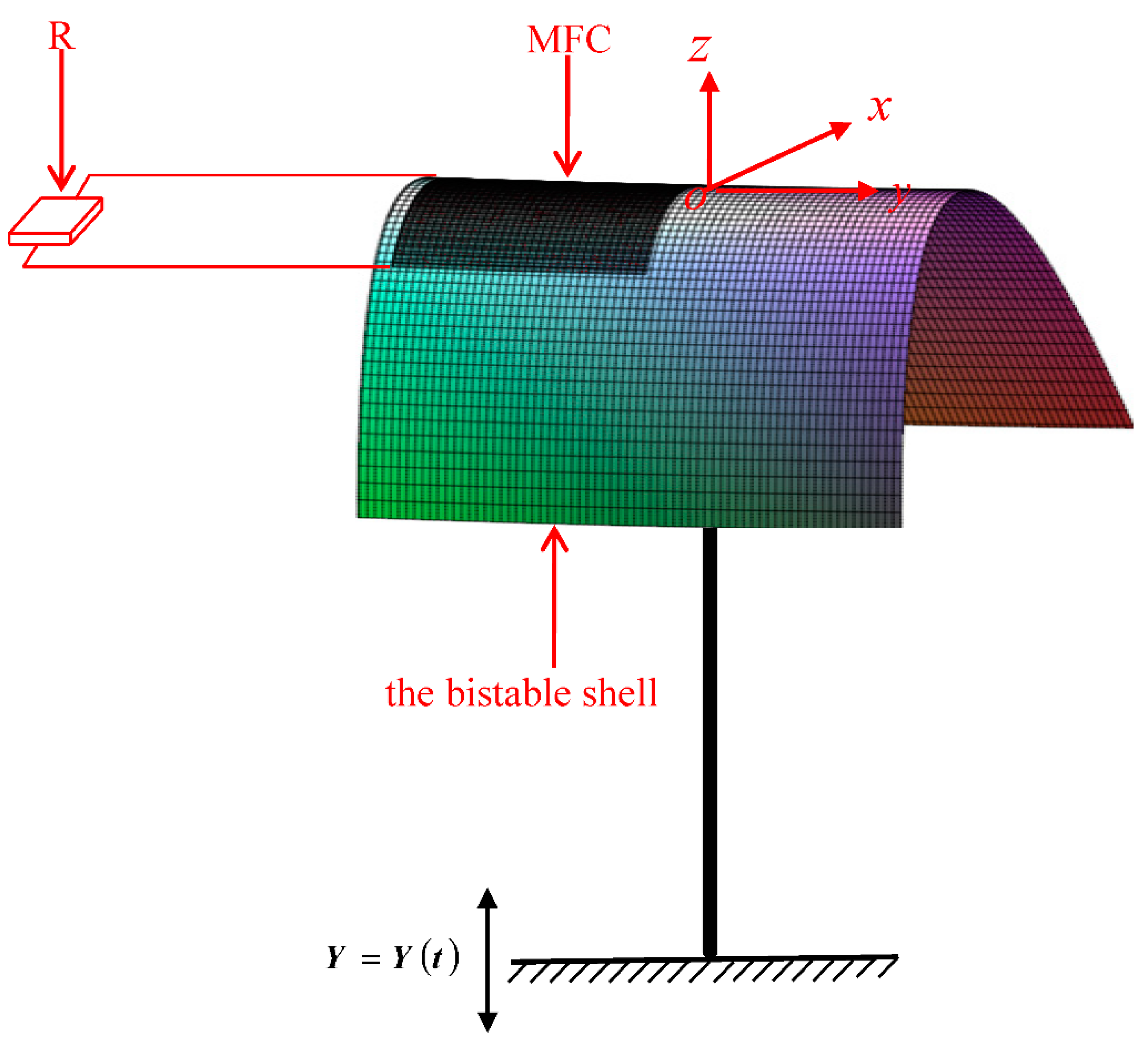
2. Dynamic Model
3. Numerical Simulation
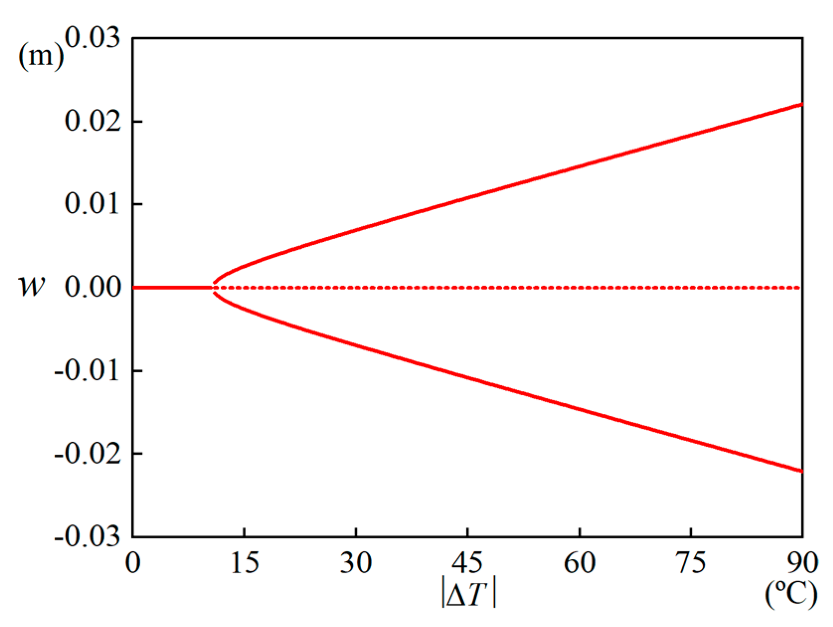
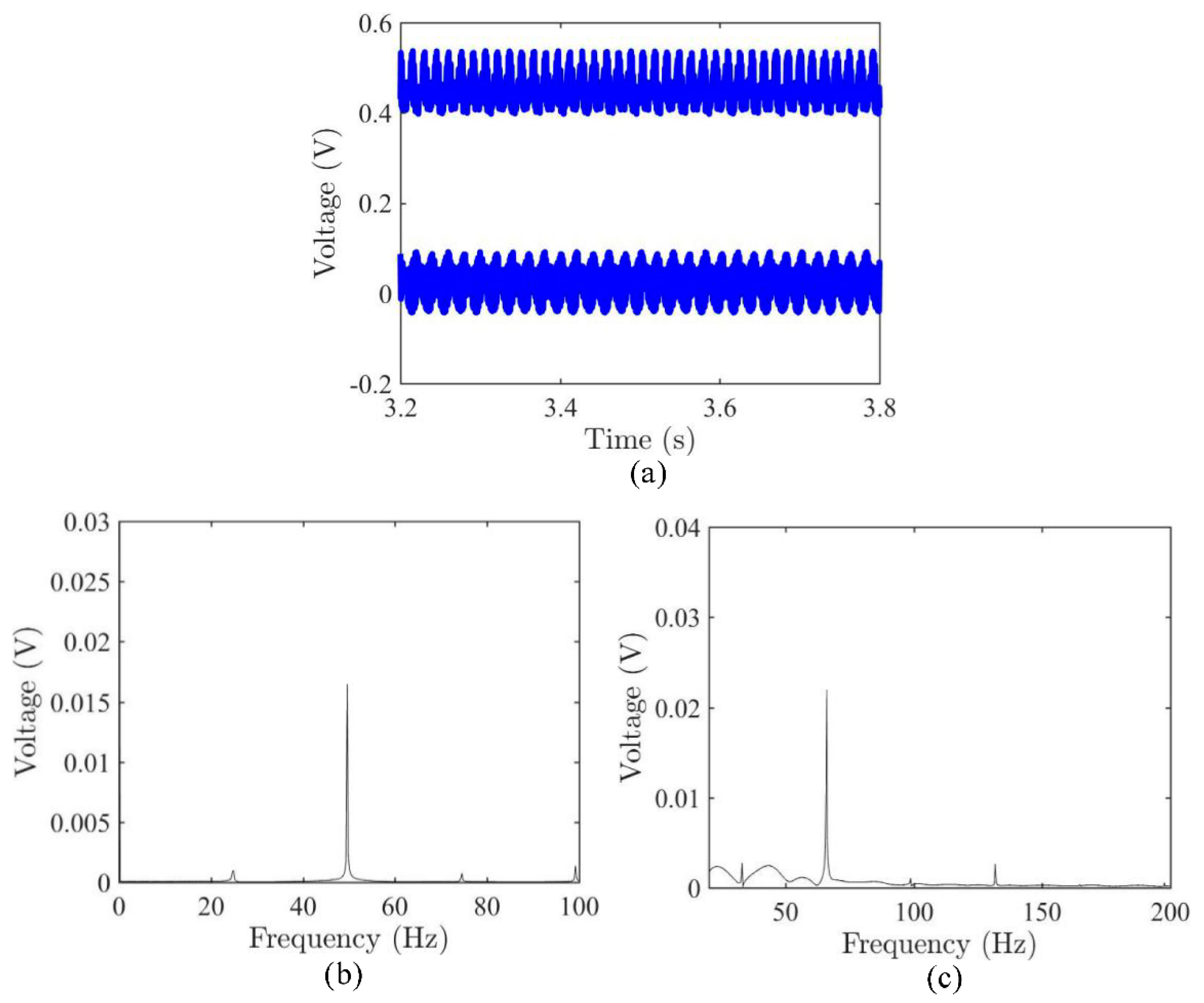
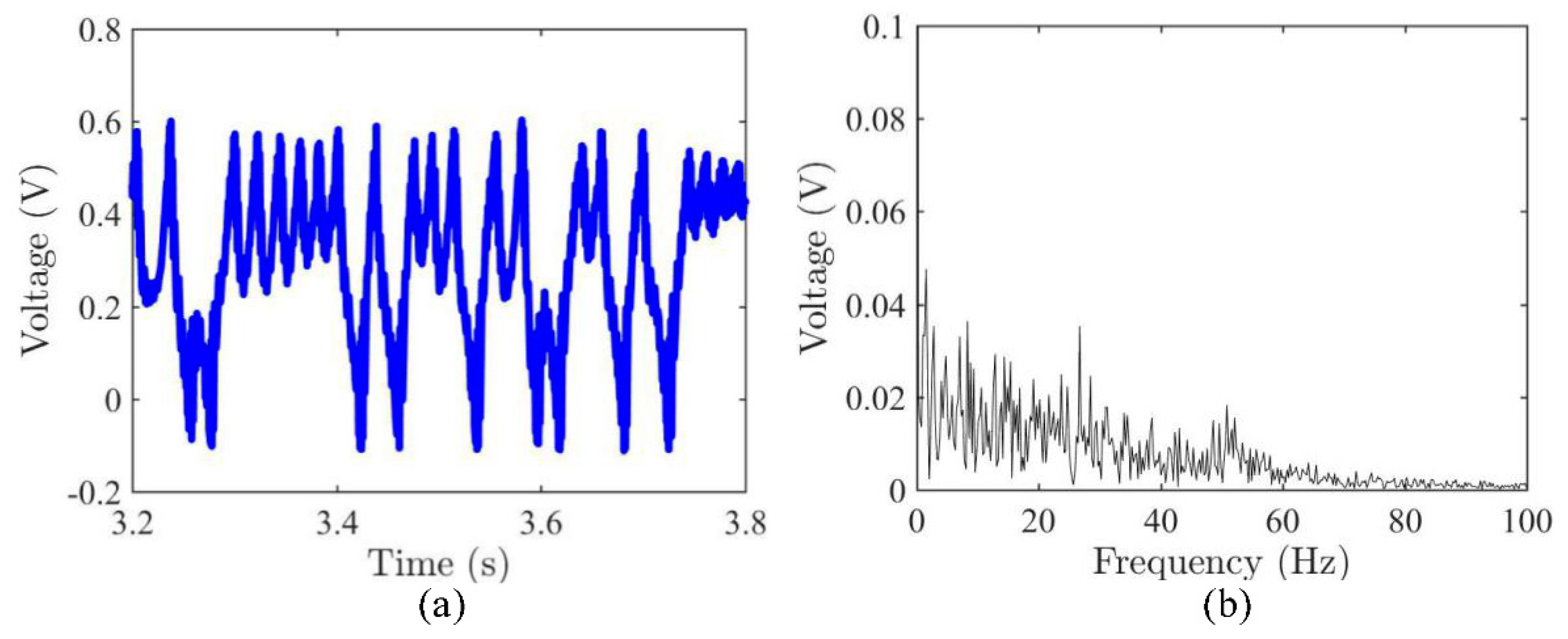
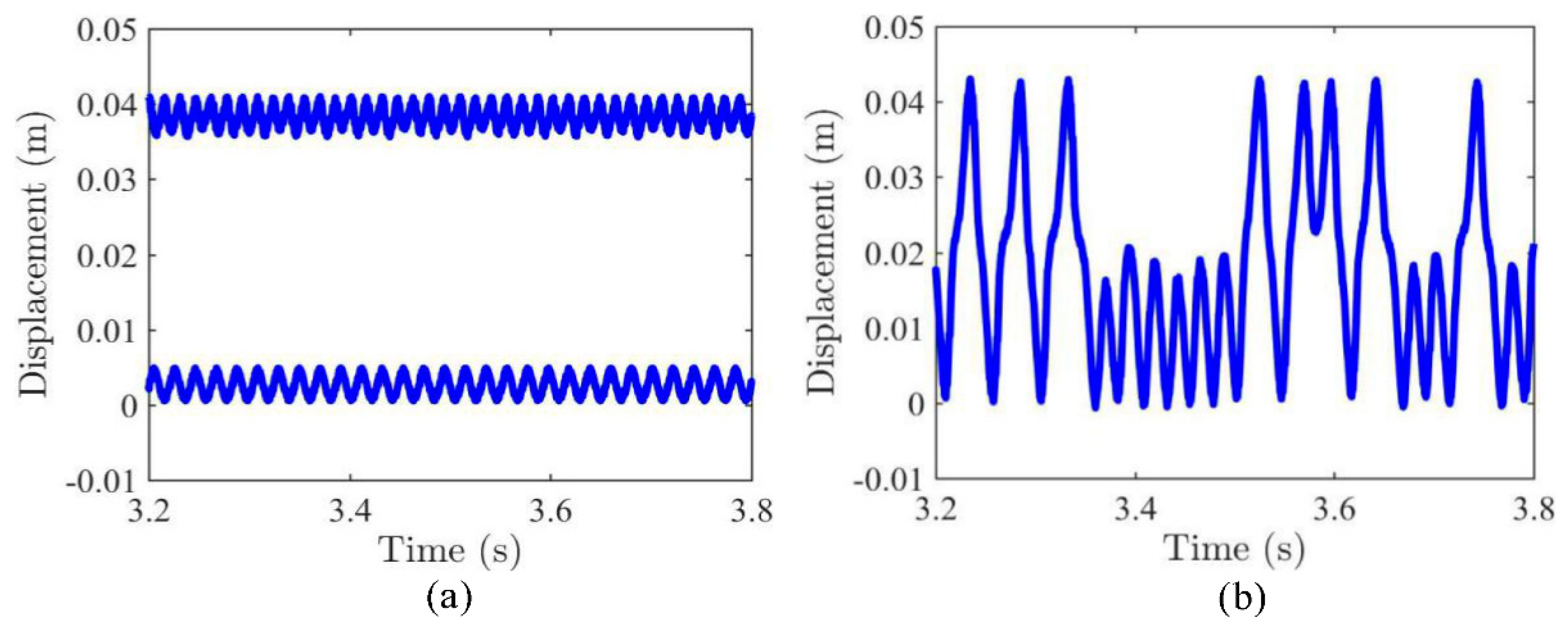
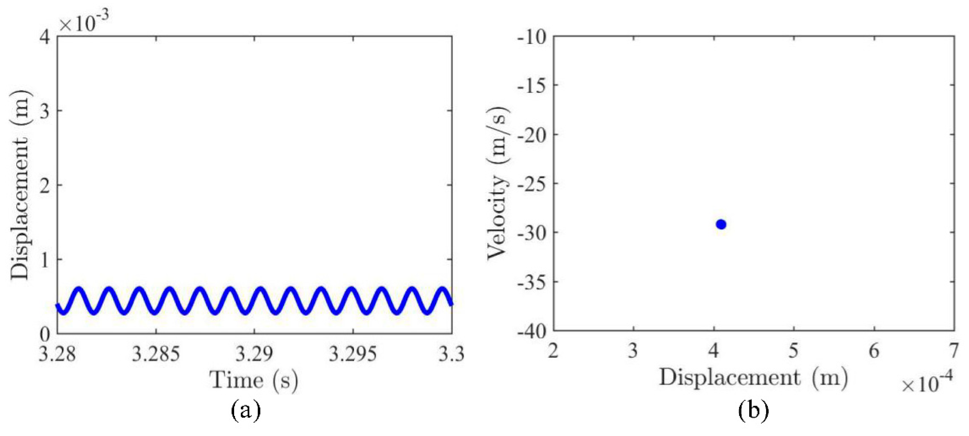
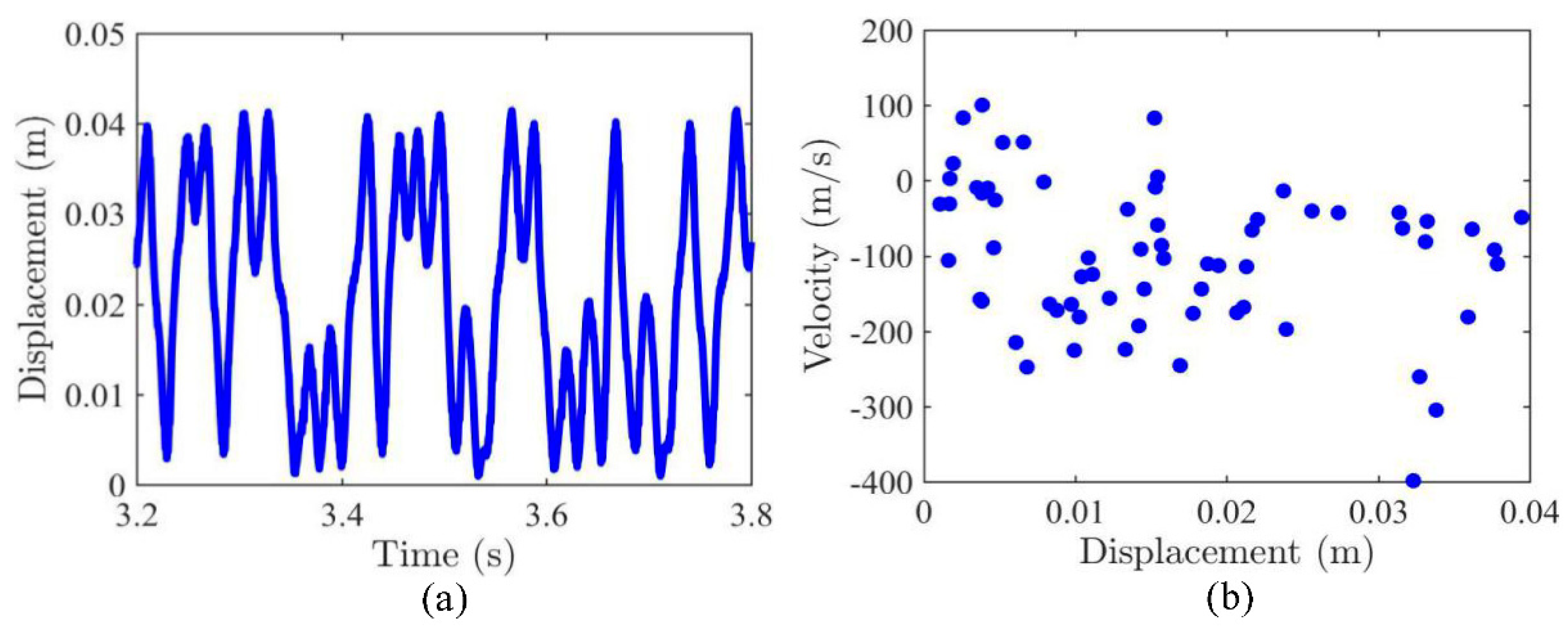
3.1. Dynamic Snap-Through and Nonlinear Vibrations
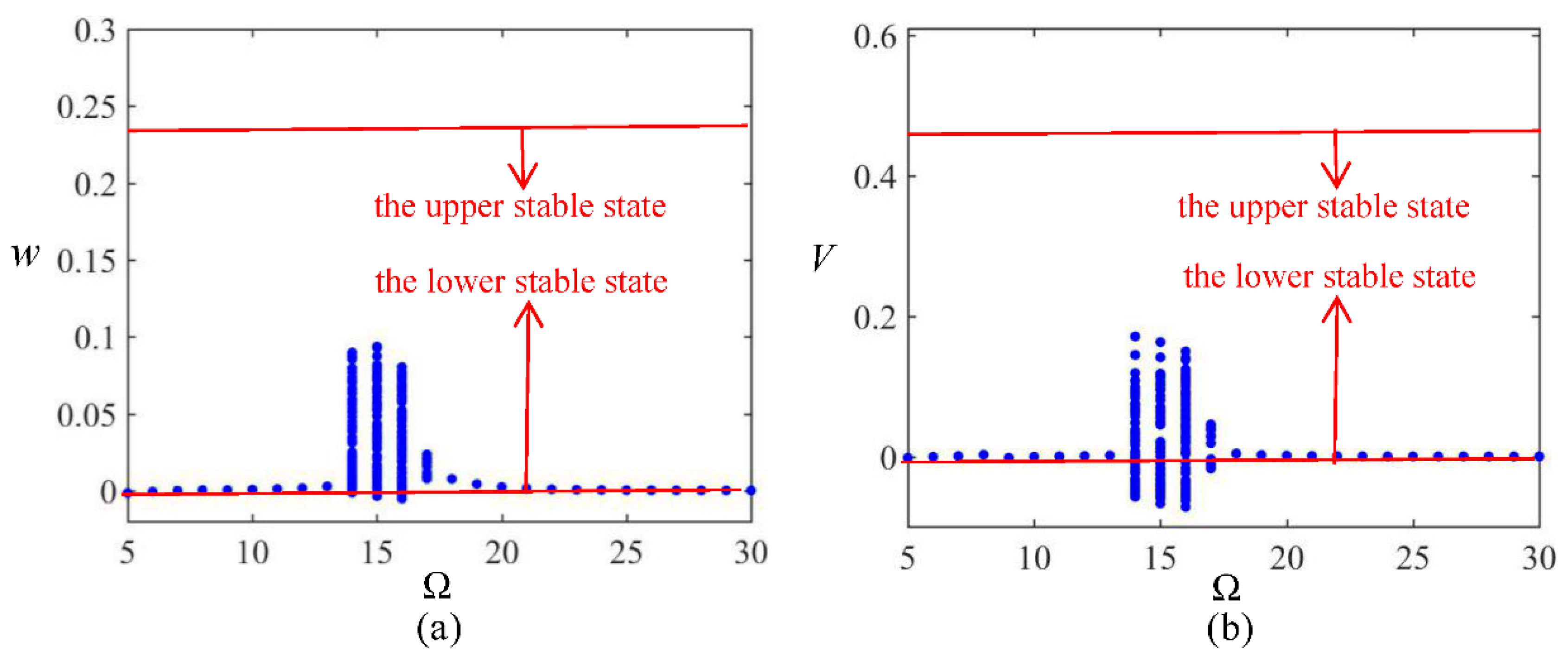
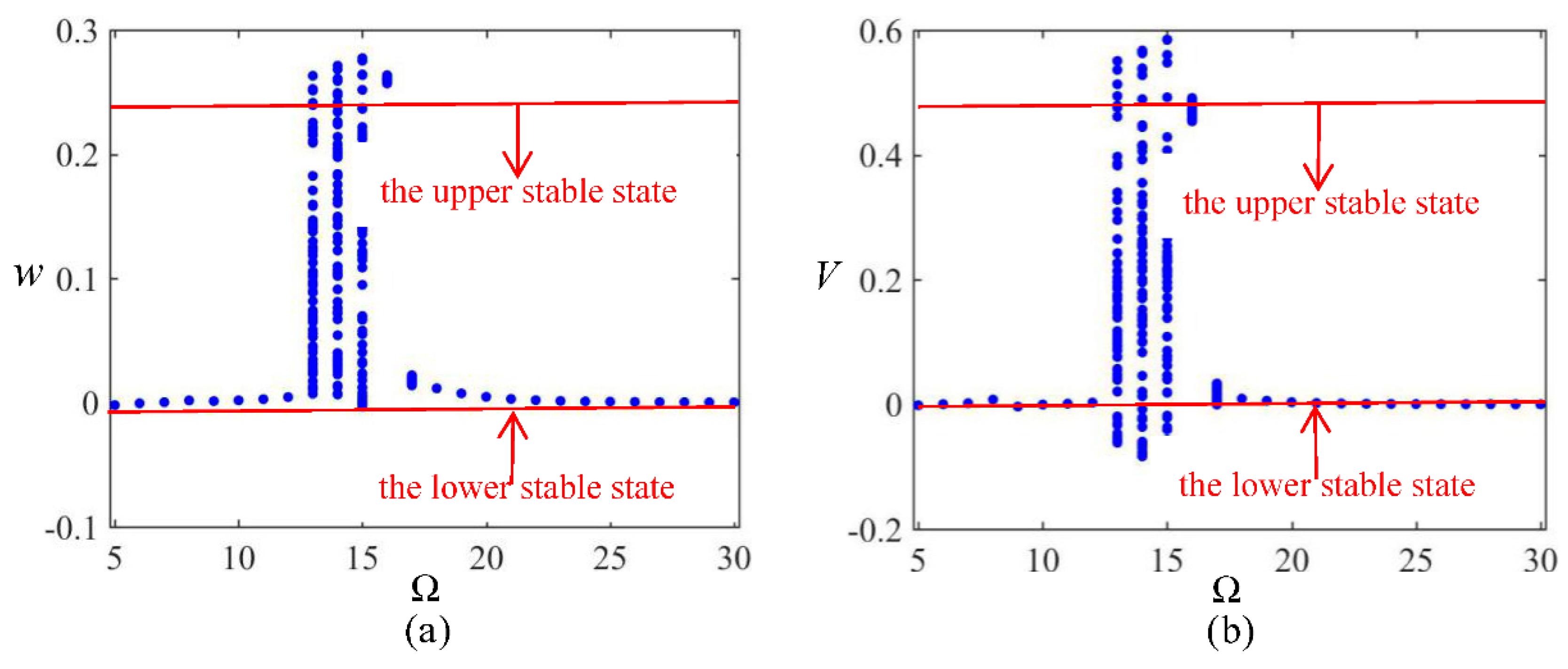
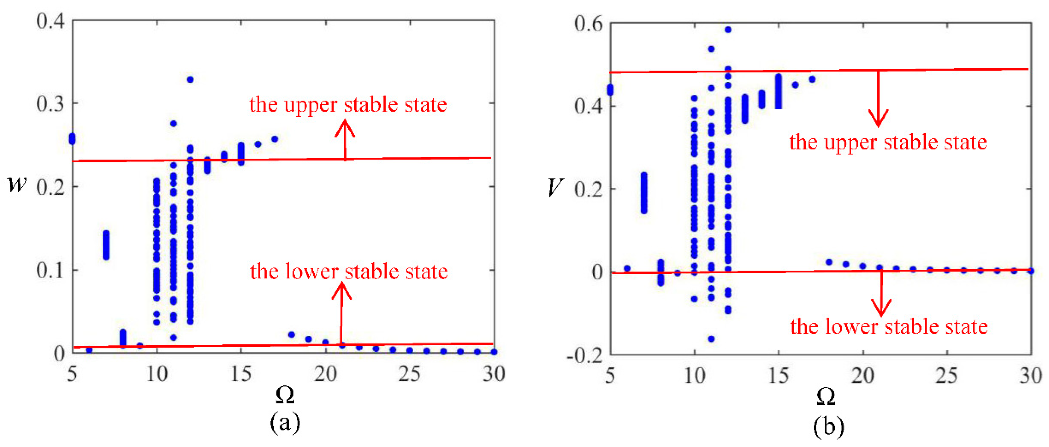
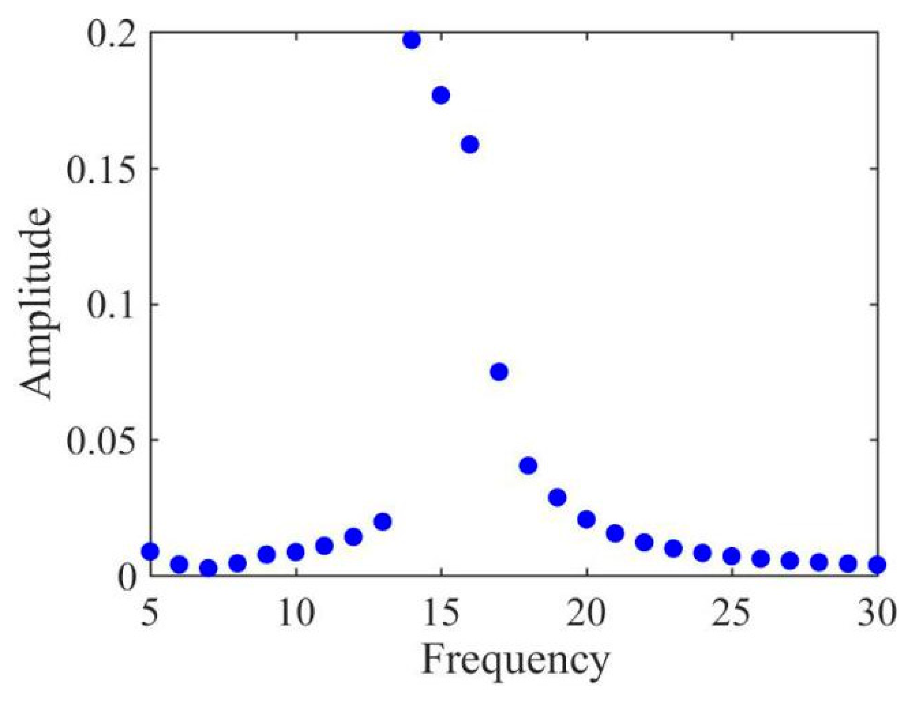
3.2. Frequency Sweeping
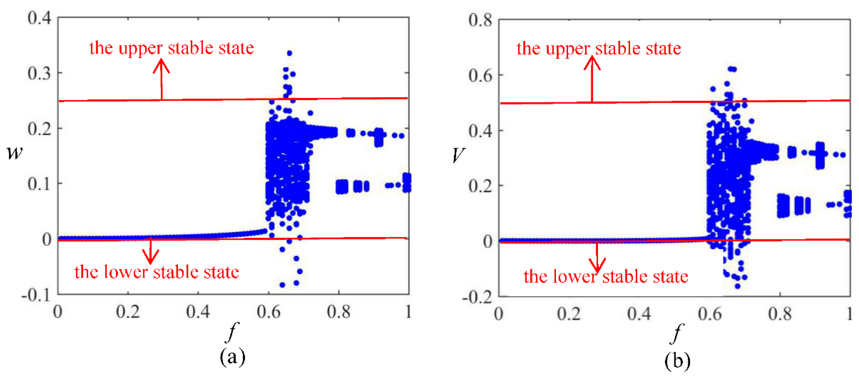
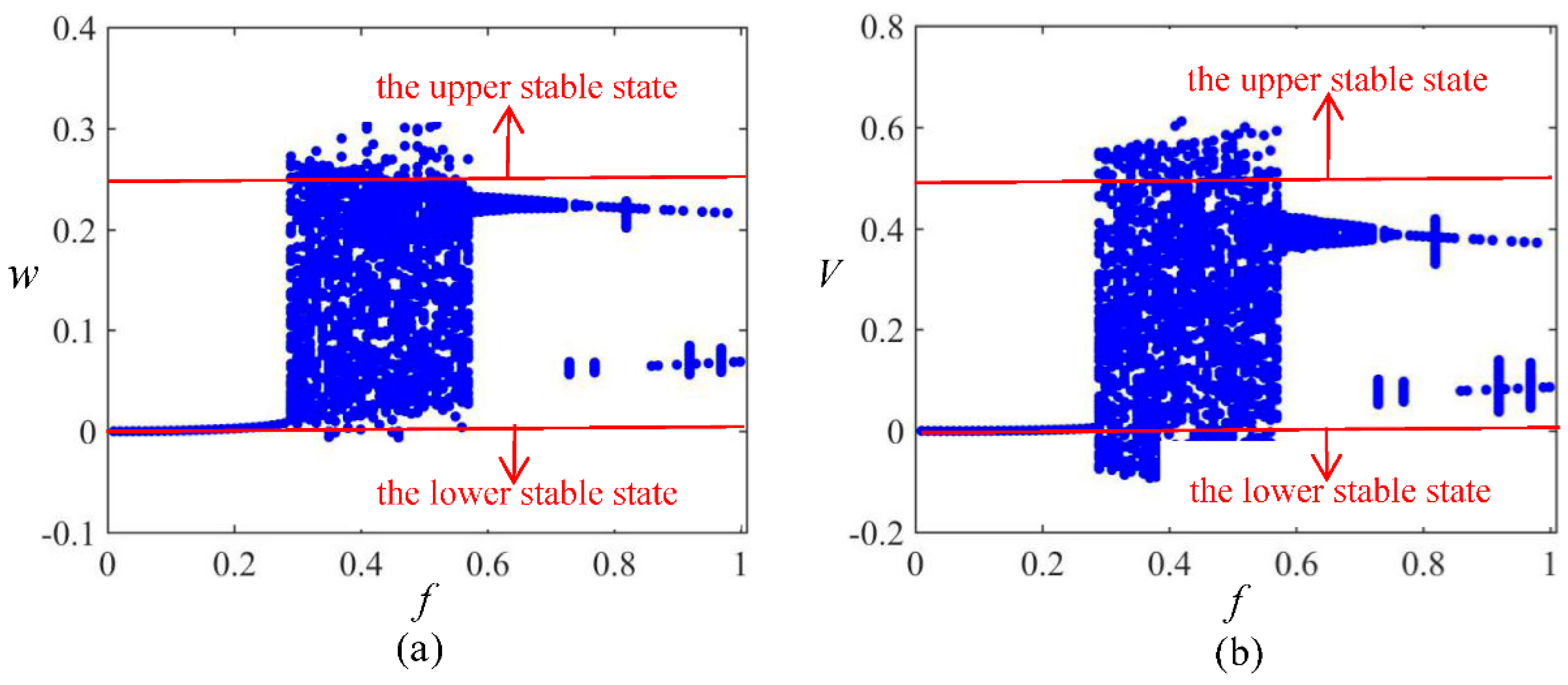
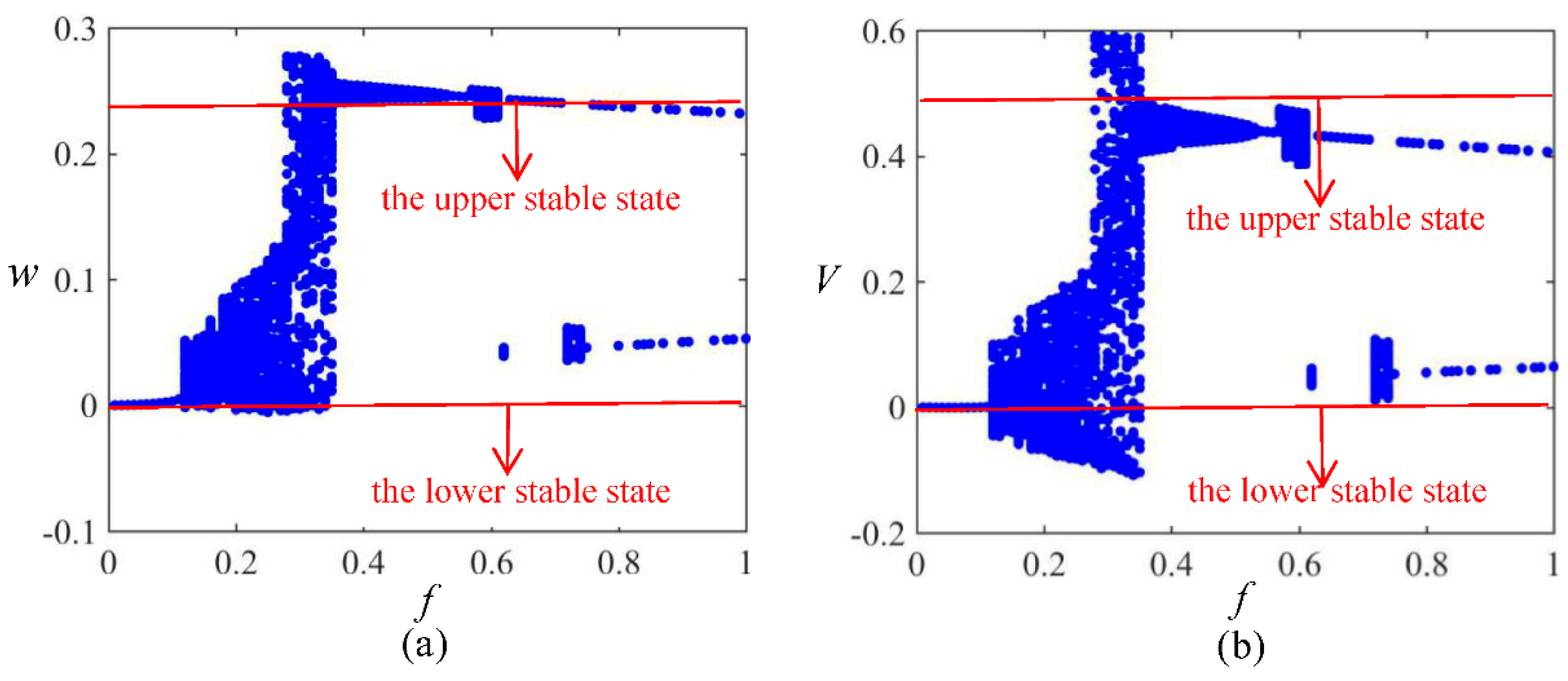
3.3. Amplitude Sweeping
4. Conclusions
Author Contributions
Funding
Institutional Review Board Statement
Informed Consent Statement
Data Availability Statement
Acknowledgments
Conflicts of Interest
References
- Emam, S.A.; Nayfeh, A.H. On the nonlinear bynamics of a buckled beam subjected to a primary-resonance excitation. Nonlinear Dyn. 2004, 35, 1–17. [Google Scholar] [CrossRef]
- Abou-Rayan, A.M.; Nayfeh, A.H.; Mook, D.T. Nonlinear response of a parametrically excited buckled beam. Nonlinear Dyn. 1993, 4, 499–525. [Google Scholar] [CrossRef]
- Lacarbonara, W.; Nayfeh, A.H.; Kreider, W. Experimental validation of reduction methods for nonlinear vibrations of distributed-parameter systems: Analysis of a buckled beam. Nonlinear Dyn. 1998, 17, 95–117. [Google Scholar] [CrossRef]
- Daynes, S.; Potter, K.D.; Weaver, P.M. Bistable Prestressed Buckled Laminates. Compos. Sci. Technol. 2008, 68, 3431–3437. [Google Scholar] [CrossRef]
- Li, H.; Dai, F.; Weaver, P.M.; Du, S. Bistable hybrid symmetric laminates. Compos. Struct. 2014, 116, 782–792. [Google Scholar] [CrossRef]
- Daynes, S.; Nall, S.J.; Weaver, P.M.; Potter, K.D.; Margaris, P.; Mellor, P.H. Bistable composite flap for an airfoil. J. Aircr. 2010, 47, 334–338. [Google Scholar] [CrossRef]
- Daynes, S.; Weaver, P.M.; Trevarthen, J.A. A morphing composite air inlet with multiple stable shape. J. Intell. Mater. Syst. Struct. 2011, 22, 961–973. [Google Scholar] [CrossRef]
- Guest, S.D.; Pellegrino, S. Analytical models for bistable cylindrical shells. Proc. R. Soc. A 2006, 462, 839–854. [Google Scholar] [CrossRef]
- Seffen, K.A. ‘Morphing’ bistable orthotropic elliptical shallow shells. Proc. R. Soc. A 2007, 463, 67–83. [Google Scholar] [CrossRef]
- Brinkmeyer, A.; Santer, M.; Pirrera, A.; Weaver, P.M. Pseudo bistable self-actuated domes for morphing applications. Int. J. Solids Struct. 2012, 49, 1077–1087. [Google Scholar] [CrossRef] [Green Version]
- Brinkmeyer, A.; Pirrera, A.; Santer, M.; Weaver, P.M. Pseudo bistable pre-stressed morphing composite panels. Int. J. Solids Struct. 2013, 50, 1033–1043. [Google Scholar] [CrossRef] [Green Version]
- Coburn, B.H.; Pirrera, A.; Weaver, P.M.; Vidoli, S. Tristability of an orthotropic doubly curved shell. Compos. Struct. 2013, 96, 446–454. [Google Scholar] [CrossRef]
- Eckstein, E.; Pirrera, A.; Weaver, P.M. Multi-mode morphing using initially curved composite plates. Compos. Struct. 2014, 109, 240–245. [Google Scholar] [CrossRef]
- Hyer, M.W. Some observations on the cured shape of thin unsymmetric laminates. J. Compos. Mater. 1981, 15, 175–194. [Google Scholar] [CrossRef]
- Hyer, M.W. Calculations of the room-temperature shapes of unsymmetric laminates. J. Compos. Mater. 1981, 15, 296–310. [Google Scholar] [CrossRef]
- Hyer, M.W. The room-temperature shapes of four-layer unsymmetric cross-ply laminates. J. Compos. Mater. 1982, 16, 318–340. [Google Scholar] [CrossRef]
- Peeters, L.J.B.; Powell, P.C.; Warnet, L. Thermally induced shapes of unsymmetric laminates. J. Compos. Mater. 1996, 30, 603–626. [Google Scholar] [CrossRef]
- Schlecht, M.; Schulte, K.; Hyer, M.W. Advanced calculation of the room-temperature shapes of thin unsymmetric composite laminates. Compos. Struct. 1995, 32, 627–633. [Google Scholar] [CrossRef]
- Schlecht, M.; Schulte, K. Advanced calculations of the room-temperature shapes of unsymmetric laminates. J. Compos. Mater. 1999, 33, 1472–1490. [Google Scholar] [CrossRef]
- Cho, M.; Choi, M.H.; Chung, H.C.; Ahn, K.J.; Eom, Y.S. A study on the room-temperature curvature shapes of unsymmetric laminates including slippage effects. J. Compos. Mater. 1998, 32, 460–482. [Google Scholar] [CrossRef]
- Gigliotti, M.; Wisnom, M.R.; Potter, K.D. Development of curvature during the cure of AS4/8552 [0/90] unsymmetric composite plates. Compos. Sci. Technol. 2003, 63, 187–197. [Google Scholar] [CrossRef]
- Dai, F.; Li, H.; Du, S. Design and analysis of a tri-stable structure based on bi-stable laminates. Compos. Part A 2012, 43, 1497–1504. [Google Scholar] [CrossRef]
- Dai, F.; Li, H.; Du, S. A multi-stable wavy skin based on bi-Stable laminates. Compos. Part A 2013, 45, 102–108. [Google Scholar] [CrossRef]
- Dai, F.; Li, H.; Du, S. A multi-stable lattice structure and its snapthrough behavior Among Multiple States. Compos. Struct. 2013, 97, 56–63. [Google Scholar] [CrossRef]
- Wang, G.Q.; Liao, W.H. A bistable piezoelectric oscillator with an elastic magnifier for energy harvesting enhancement. J. Intell. Mater. Syst. Struct. 2016, 28, 392–407. [Google Scholar] [CrossRef]
- Cottone, F.; Basset, P.; Vocca, H.; Gammaitoni, L.; Bourouina, T. Bistable electromagnetic generator based on buckled beams for vibration energy harvesting. J. Intell. Mater. Syst. Struct. 2013, 25, 1484–1495. [Google Scholar] [CrossRef]
- Harne, R.L.; Wang, K.W. A review of the recent research on vibration energy harvesting via bistable systems. Smart Mater. Struct. 2013, 22, 023001. [Google Scholar] [CrossRef]
- Stanton, S.C.; Mcgehee, C.C.; Mann, B.P. Nonlinear dynamics for broadband energy harvesting: Investigation of a bistable piezoelectric inertial generator. Phys. D Nonlinear Phenom. 2010, 239, 640–653. [Google Scholar] [CrossRef]
- Mann, B.P.; Owens, B.A. Investigations of a nonlinear energy harvester with a bistable potential well. J. Sound Vib. 2010, 329, 1215–1226. [Google Scholar] [CrossRef]
- Arrieta, A.F.; Hagedorn, R.; Erturk, R.; Inman, R.J. A piezoelectric bistable plate for nonlinear broadband energy harvesting. Appl. Phys. Lett. 2010, 97, 174103. [Google Scholar] [CrossRef] [Green Version]
- Lee, A.J.; Inman, D.J. A multifunctional bistable laminate: Snap-through morphing enabled by broadband energy harvesting. J. Intell. Mater. Syst. Struct. 2018, 29, 2528–2543. [Google Scholar] [CrossRef] [Green Version]
- Syta, A.; Bowen, C.R.; Kim, H.A.; Rysak, A.; Litak, G. Experimental analysis of the dynamical response of energy harvesting devices based on bistable laminated plates. Meccanica 2015, 50, 1961–1970. [Google Scholar] [CrossRef] [Green Version]
- Emam, S.A.; Hobeck, J.; Inman, D.J. Experimental investigation into the nonlinear dynamics of a bistable laminate. Nonlinear Dyn. 2019, 95, 3019–3039. [Google Scholar] [CrossRef]
- Emam, S.A.; Inman, D.J. A review on bistable composite laminates for morphing and energy harvesting. Appl. Mech. Rev. 2015, 67, 060803. [Google Scholar] [CrossRef]
- Pellegrini, S.P.; Tolou, N.; Schenk, M.; Herder, J.L. Bistable vibration energy harvesters: A review. J. Intell. Mater. Syst. Struct. 2013, 24, 1303–1312. [Google Scholar] [CrossRef]
- Lu, Z.Q.; Shao, D.; Fang, Z.W.; Ding, H.; Chen, L.Q. Integrated vibration isolation and energy harvesting via a bistable piezo-composite plate. J. Vib. Control 2020, 26, 779–789. [Google Scholar] [CrossRef]
- Borowiec, M.; Rysak, A.; Betts, D.N.; Bowen, C.R.; Kim, H.A.; Litak, G. Complex response of a bistable laminated plate: Multiscale entropy analysis. Eur. Phys. J. Plus 2014, 129, 1–7. [Google Scholar] [CrossRef] [Green Version]
- Reddy, A.N. Mechanics of Laminated Composite Plates and Shells: Theory and Analysis; CRC Press: Boca Raton, FL, USA, 2004; pp. 200–216. [Google Scholar]
- Pirrera, A.; Avitabile, D.; Weaver, P.M. Bistable plates for morphing structures: A refined analytical approach with high-order polynomials. Int. J. Solids Struct. 2010, 47, 3412–3425. [Google Scholar] [CrossRef] [Green Version]
- Sembiring, L.; van Ormondt, M.; van Dongeren, A.; Roelvink, D. A validation of an operational wave and surge prediction system for the Dutch coast. Nat. Hazards Earth Syst. Sci. 2015, 15, 1231–1242. [Google Scholar] [CrossRef] [Green Version]
- Gude, M.; Hufenbach, W.; Kirvel, C. Piezoelectrically driven morphing structures based on bistable unsymmetric laminates. Compos. Struct. 2011, 93, 377–382. [Google Scholar] [CrossRef]


| Properties | Description | Data | Unit |
|---|---|---|---|
| E11 | The longitudinal modulus | 147 | GPa |
| E22 | The transverse modulus | 10.7 | GPa |
| G12 | The shear modulus | 7 | GPa |
| G13 | The shear modulus | 7 | GPa |
| G23 | The shear modulus | 7 | GPa |
| ν12 | The major Poisson’s ratio | 0.3 | – |
| α1 | The longitudinal coefficient of thermal expansion | 5 × 10⁻⁷ | [°C]−1 |
| α2 | The transversal coefficient of thermal expansion | 2.649 × 10⁻⁵ | [°C]−1 |
| h | The thickness of the fiber | 0.122 | mm |
| Lx | The length of the fiber | 300 | mm |
| Ly | The width of the fiber | 300 | mm |
| Properties | Description | Data | Unit |
|---|---|---|---|
| E11 | The longitudinal modulus | 30.336 | GPa |
| E22 | The transverse modulus | 15.857 | GPa |
| G12 | The shear modulus | 5.515 | GPa |
| G13 | The shear modulus | 5.515 | GPa |
| G23 | The shear modulus | 6.823 | GPa |
| ν12 | The major Poisson’s ratio | 0.31 | – |
| e31 [10−9 mm/V] | The piezoelectric constant | −210 | 10−9 mm/V |
| e32 [10−9 mm/V] | The piezoelectric constant | −210 | 10−9 mm/V |
| e33 [10−9 mm/V] | The piezoelectric constant | 460 | 10−9 mm/V |
| h | The thickness of the MFC | 0.3 | mm |
| Lx | The length of the MFC | 85 | mm |
| Ly | The width of the MFC | 57 | mm |
Publisher’s Note: MDPI stays neutral with regard to jurisdictional claims in published maps and institutional affiliations. |
© 2021 by the authors. Licensee MDPI, Basel, Switzerland. This article is an open access article distributed under the terms and conditions of the Creative Commons Attribution (CC BY) license (https://creativecommons.org/licenses/by/4.0/).
Share and Cite
Dong, T.; Chen, X.; Zhang, J. Study on Dynamic Snap-Through and Nonlinear Vibrations of an Energy Harvester Based on an Asymmetric Bistable Composite Laminated Shell. Symmetry 2021, 13, 2405. https://doi.org/10.3390/sym13122405
Dong T, Chen X, Zhang J. Study on Dynamic Snap-Through and Nonlinear Vibrations of an Energy Harvester Based on an Asymmetric Bistable Composite Laminated Shell. Symmetry. 2021; 13(12):2405. https://doi.org/10.3390/sym13122405
Chicago/Turabian StyleDong, Ting, Xinhua Chen, and Jun Zhang. 2021. "Study on Dynamic Snap-Through and Nonlinear Vibrations of an Energy Harvester Based on an Asymmetric Bistable Composite Laminated Shell" Symmetry 13, no. 12: 2405. https://doi.org/10.3390/sym13122405