Article

Protection and Fault Isolation Scheme for DC Distribution Network Based on Active Current-Limiting Control

by
Langheng Cao
1,
Jiawen Lv
2,
Jing Chen
3,
Feng Zheng
2,* and
Ning Liang
4
1
Guangdong Electric Power Research Institute, China Energy Construction Corporation, Guangzhou 510663, China
2
School of Electrical Engineering and Automation, Fuzhou University, Fuzhou 350108, China
3
State Grid Lanzhou Power Supply Company, Lanzhou 730000, China
4
College of Electric Power Engineering, Kunming University of Science and Technology, Kunming 650500, China
*
Author to whom correspondence should be addressed.
Symmetry 2024, 16(10), 1275; https://doi.org/10.3390/sym16101275
Submission received: 16 July 2024 / Revised: 31 August 2024 / Accepted: 23 September 2024 / Published: 27 September 2024
(This article belongs to the Section Computer)

Abstract

:
Aiming at the problems of high peak value fault current, fast rising speed, and being unable to ensure the reliability of the power supply in the non-fault zone in a multi-terminal DC system, a new cascade flexible current limiter and mechanical DC circuit breaker for medium- and high-voltage distribution networks are proposed. Firstly, the flexible current limiter is triggered by differential under-voltage protection to achieve the effect of interpole voltage clamping, suppressing the fault current and improving the dynamic recovery characteristics of the DC system after fault clearing. Secondly, according to the breaking speed of the DC circuit breaker, the action time of the current limiter can be set flexibly. The directional pilot protection signal of the circuit breaker is used to ensure the continuous action of the current limiter at the converter station side in the fault zone, until the circuit breaker acts to isolate the fault. The protection strategy can also avoid the blocking of the converter station and reduce the requirements for the breaking speed and breaking capacity of the circuit breaker. Finally, a four-terminal medium voltage distribution network model is built in MATLAB/SIMULINK, and the effect of the current limiter and the feasibility of the proposed protection strategy are verified by simulation.

1. Introduction

In recent years, the increasing penetration of distributed energy resources has highlighted the limitations of traditional Alternating Current (AC) distribution networks in meeting the diverse and growing demands for electricity, as well as the higher standards for power quality. Direct Current (DC) distribution networks, offering large transmission capacity, superior power quality, low line losses, and more flexible control, have emerged as a promising solution [1,2,3].
However, due to the low impedance and inertia of DC systems, fault currents can be extremely high, reaching peak levels within a few milliseconds when a fault occurs. The power electronic devices currently used in DC systems are not well-equipped to withstand such high currents [4]. To prevent damage to system components, it is essential to clear faults rapidly. Fundamental differences between AC and DC distribution networks—such as system architecture, operation modes, fault characteristics, and measurement methods—mean that traditional AC protection technologies cannot be directly applied to DC systems [5,6,7].
Building on the protection schemes used in traditional AC systems and existing DC transmission systems, protection strategies can be categorized into single-ended electrical magnitude protection, differential protection, boundary protection, and double-ended longitudinal protection [8,9,10]. However, each of these approaches has limitations. Single-ended protection schemes often lack selectivity and are primarily used for fault detection. Differential protection, which is sensitive to transition resistance, requires coordination with under-voltage protection to be effective. Boundary protection lacks a universal method for selecting boundary parameters and protection thresholds, while the communication and data synchronization issues inherent in double-ended longitudinal protection reduce the speed of fault clearance [11,12].
Given these limitations, DC circuit breakers face higher demands for breaking speed and capacity [13]. Fault current limiters (FCLs) can effectively reduce the rate of rise and magnitude of fault currents, making it feasible to combine FCLs with protection schemes for more flexible, rapid, and accurate fault clearance. Previous studies have proposed boundary protection strategies based on the inherent characteristics of FCLs [14,15,16]. However, as fault current suppression strategies evolve, the parameters of current-limiting reactors have decreased, weakening the boundary effects. Another study proposed a protective timing coordination method with an FCL, but it focused solely on fault clearance and did not address system recovery [17]. While other papers have suggested using superconducting current limiters, these devices require large, reliable cooling systems to prevent overheating, which increases both their size and cost [18,19]. The main drawback of current protection schemes involving FCLs is their inflexibility—they merely coordinate current limiting with circuit breaker operation in a fixed sequence, without adapting the protection strategy after the FCL is added. Additionally, the size and cost of FCLs remain significant concerns.
To address these challenges, this paper presents a novel protection strategy for multi-terminal DC distribution networks (MTDCs) based on a flexible current limiter. The proposed strategy integrates differential under-voltage protection into the control module of a new flexible current limiter for fault monitoring, ensuring that changes in the limiter’s parameters do not affect fault detection. Upon detecting a fault, the current limiter quickly activates, raising the voltage to the corresponding fault set point, thereby clamping the voltage and limiting the fault current to a lower level. Directional longitudinal protection is then used to distinguish between internal and external faults. This paper further analyzes protection strategies combining the flexible current limiter with mechanical circuit breakers in Voltage Source Converter–Multi-Terminal Direct Current (VSC–MTDC) systems, detailing the fault-handling process for this combination. Finally, the feasibility and effectiveness of the proposed protection strategy are validated through simulations in MATLAB/SIMULINK R2018b.

2. DC Distribution Network Equipment
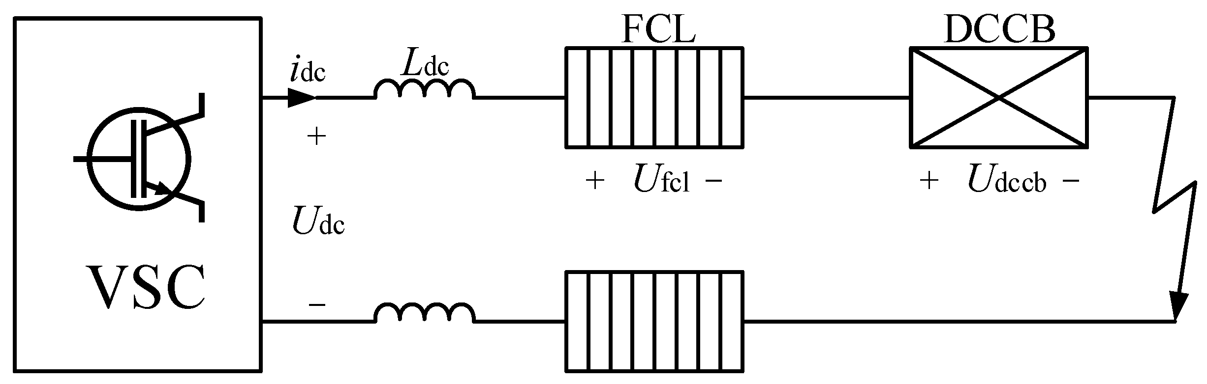
2.1. VSC Converter

The major AC network needs to connect with the DC distribution network through inverters. The converters commonly used for AC–DC conversion are active Voltage Source Converters (VSCs) and Line Commutated Converters (LCCs). The DC-side voltage level is ±5 kV. Considering the configuration of the current limiter and economic factors, a two-level VSC is selected as the grid connection interface between the DC distribution network and the main power grid.
The topology of the VSC converter in the DC network is shown in Figure 1. The converter is composed of an IGBT bridge, filter, capacitor, etc. In the diagram, Ea, Eb, and Ec are the AC-side three-phase voltages, Ia, Ib, and Ic are the AC-side three-phase currents, R is the line equivalent resistance, L is the filter inductance, and Udc is the DC-bus voltage.
A VSC three-phase voltage loop equation is obtained by Kirchhoff’s Voltage Law (KVL) after a three-phase VSC mathematical model is established:
E a E b E c = U o a U o b U o c + L d I a d t d I b d t d I c d t + R I a R I b R I c
Based on Kirchhoff’s Current Law (KCL), the current equation of the DC-side capacitive positive node can be obtained:
I c = C d U dc d t = S a I a + S b I b + S c I c i L
Si (i = a, b, c) is defined as a switch function. When Si = 1, the upper arms conduct, and the lower arms break; when Si = 0, the lower arms conduct, and the upper arms break.
Using the Park transformation, Equations (1) and (2) are converted from three-phase stationary coordinates to dq0 synchronous rotating coordinates. The resulting transformed equation is given by Equation (3), where ω represents the synchronous angular frequency.
E d = u d + L d i d d t + R i d ω L i q E q = u q + L d i q d t + R i q + ω L i d C d U d c d t = 3 2 ( S d i d + S q i q ) i L
In steady state, assuming that the system is three-phase symmetrical, which means there is no zero-sequence component, and adopting grid voltage directional vector control (Ed = Em, Eq = 0, where Em is the phase voltage amplitude), the grid-connected active power P and reactive power Q are as follows:
P = 3 2 ( E d i d + E q i q ) = 3 2 E d i d Q = 3 2 ( E q i d E d i q ) = 3 2 E d i q
Formula (4) shows that by controlling id and iq, respectively, the purpose of controlling the steady-state active and reactive power can be achieved. The VSC can be divided into PQ control and constant voltage control according to the working mode of the DC distribution network. The control model will not be detailed here.

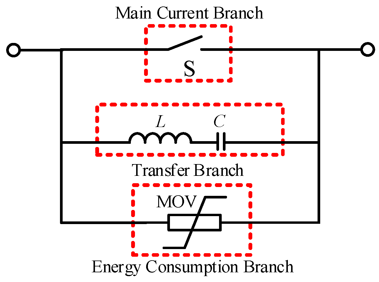
2.2. Mechanical DC Circuit Breaker

This paper selects a mechanical DC circuit breaker in coordination with the current limiter. The current limiter’s ability to reduce both the amplitude and the rise rate of the fault current alleviates the circuit breaker’s need for rapid fault interruption. As a result, more economical and easier-to-operate mechanical DC circuit breakers can be utilized.
The structure of the mechanical DC circuit breaker is illustrated in Figure 2. Under normal operating conditions, the working current flows through the main current branch via the mechanical switch S, resulting in very low static losses. However, when a fault occurs on the DC side, disconnecting the switch causes an arc to form, which is difficult to extinguish due to the absence of a natural zero-crossing point in the short-circuit current. To address this challenge, an LC self-excited oscillation structure is integrated into the mechanical DC circuit breaker, building on the design of the AC circuit breaker. The reverse current generated by this structure counters the fault current, creating a zero-crossing point. At this moment, the arc extinguishing process is initiated, and the current is subsequently transferred to the energy dissipation branch. The lightning arrester then absorbs the fault energy, effectively eliminating the fault.

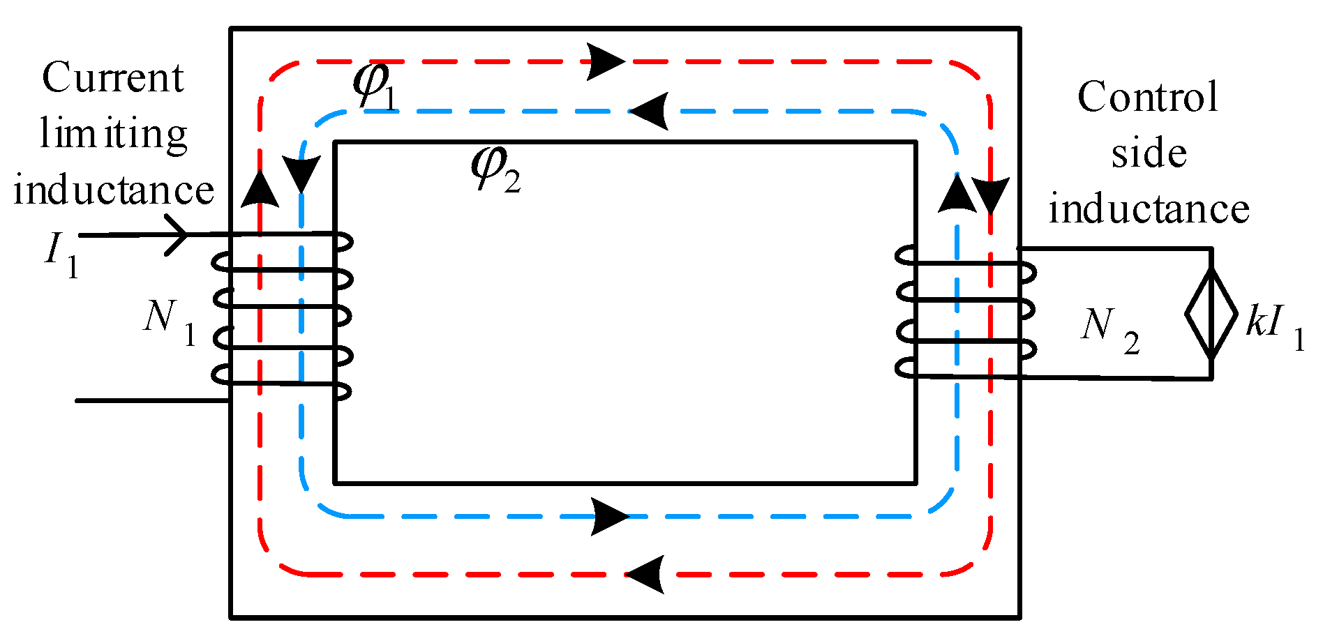
2.3. Flexible Current Limiter

For the new flexible current limiter proposed in this paper to function effectively in medium- and high-voltage distribution networks, a cascade configuration is required to achieve the desired current-limiting effect while addressing economic considerations. Under normal operating conditions, the rectifier circuit bypasses the flexible current limiter, minimizing the impact on the system. In the event of a fault, the rectifier structure provides the current-limiting inductance with a reverse clamping voltage, thereby reducing the fault current. Figure 3 illustrates the structure of the flexible current limiter.
When the system is in normal operation, the AC side does not supply voltage to the current-limiting inductance. Therefore, UL1, UL2ULn are close to 0 and the static loss is low. Here, the circuit voltage equation in the system is as follows:
U d = U L L + U R L + U R
where U L L and U R L are the equivalent inductance and resistance voltage, and UR is the load voltage.
When the system fails, the AC side supplies the reverse voltage to the current-limiting inductors through the rectifier, and the system voltage loop equation is as follows:
U dc = U L L + U R L + U R + U L 1 + U L 2 + + U L n
Due to the low voltage and line equivalent resistance on the load, UdcUL1 + UL2 + … + ULn. Consequently, the capacitor voltage is clamped to the voltage across the flexible current limiter. The capacitor on the DC side causes the fault current to generate a large voltage in a short period. As the capacitor’s discharge voltage decreases to its minimum value, the fault current amplitude is also reduced to a minimum. The inclusion of the current limiter in the system introduces inductance, which further reduces the fault current’s rise rate, thereby achieving a dual current-limiting effect.
Given the voltage level set in this paper is ±5 kV, if the current limiter employs a single inductance, the voltage across the inductance would need to approach 5 kV. This necessitates selecting a large inductor to meet the voltage requirements, which, however, would result in a bulky component or high demands on the current withstand capacity, raising issues of size and cost. Conversely, selecting a small inductor would cause it to saturate instantaneously, negating the current-limiting effect. To address these challenges, a flexible current-limiting module with a series inductance configuration is chosen for the ±5 kV network. Inductance parameters, balancing size and economy, can be tested and selected in a ±500 V network before being installed in equal quantities at the beginning of both the positive and negative DC lines. Each of the positive and negative poles contains five cascaded sub-modules. The inductance selection requirements are described as follows.
When designing a traditional current limiter, the following three issues need to be considered:
(1)
In order to match the DC circuit breaker breaking fault current, the maximum value of the fault current should be less than the breaking current of the circuit breaker;
(2)
In order to ensure the safe operation of the circuit breaker, the change rate of the current on the DC side should be less than the maximum change rate of the circuit breaker;
(3)
In order to protect the diode of the converter station, the sum of the DC fault detection time and the fault clear time should be less than the discharge time of the DC capacitor.
Therefore, the constraints of the fault current and circuit breaker are as follows:
max I d c < I C B max max ( d I d c / d t ) < ( d i / d t ) C B max t F D T + t C B < t C D T
where ICBmax is the breaking current of the circuit breaker; Idc is the line current, tFDT is the fault detection time; tCB is the failure breaking time; and tCDT is the discharge time of the capacitor.
In the case of small fluctuations of the single-pole ground fault current and short-circuit fault between electrodes, the DC fault current and the conversion rate of the fault current can be limited to a lower value. Therefore, the current limiter proposed in this paper is not restricted by the traditional constraint conditions. Energy loss is also used as an important index in the selection of current-limiting inductors. During the fault, the rectifier charges the current-limiting inductor L1, and the inductor current I1 rises with a fixed slope. Assuming that the time of the fault occurrence is T1, the time of fault removal is T2, and the time of saturation of the current-limiting inductor is T3, the energy stored by the inductor can be expressed as follows:
W 1 = T 1 T 2 L 1 I 1 ( t ) d t T 2 < T 3 T 1 T 3 L 1 I 1 ( t ) d t + T 3 T 2 L 1 ( t ) I 1 d t T 2 > T 3  
I 1 ( t ) = ( t T 1 ) U 1 L 1 L 1 ( t ) = L 1 + U 1 I s ( t T 3 )
where Is is the saturation current of the current-limiting inductor and Ul is the inductor voltage. When the fault removal time is longer than the saturation time of the current-limiting inductor, the controlled voltage source is used to eliminate the inductor saturation. It can be seen from the above that the current-limiting inductance increases linearly and the inductor current is a constant value. Therefore, according to the integral equivalence principle, the inductor energy expression is modified as follows:
W 1 = L 1 I T 2 ( T 2 T 1 ) 2 T 2 < T 3 L 1 I s ( T 2 T 3 2 T 2 2 ) + U 1 2 ( T 2 T 3 ) 2 T 2 > T 3
where IT2 is the current of the current-limiting inductor at time T2.
In summary, the maximum current flowing through the inductor cannot exceed the saturation current, and the maximum stored energy WS of the inductor should be less than or equal to W1, that is
I s I T 2 W S W 1
Therefore, the selection range of inductors is
L 1 W S U 1 2 ( T 3 T 2 ) 2 I S ( T 2 T 3 2 T 1 2 )
To address the issue of current-limiting inductance saturation, the following solutions are proposed. When the current-limiting inductance becomes saturated, the slope of the current flowing through it no longer increases but remains constant. As a result, the voltage across the inductance can no longer be maintained stably, the capacitive voltage fails to be clamped, and the current-limiting effect is lost. To mitigate this, a closed-core design is employed to prevent inductance saturation. The closed-core structure is illustrated in Figure 4.
In the figure, N1 represents the current-limiting side inductance, while N2 denotes the control side inductance. The red dashed line indicates the direction of the flux generated through the left winding, that is, the magnetic field generated by the current on the input side, bypassing the core to the control side. The blue dashed line indicates the direction of the flux generated through the right winding, that is, the magnetic field generated by the current on the control side, bypassing the core and flowing to the input side. The saturation of the current-limiting inductance occurs due to the internal magnetic flux saturation within N1. This structure mitigates the rising magnetic flux in N1 by introducing reverse magnetic flux through N2 via a secondary controlled source, thereby achieving a desaturation effect.
The magnetic flux loop equation of the closed core is as follows:
φ 1 = L 1 I 1 ψ 1 = N 1 φ 1 e 1 = d ψ 1 / d t
In the formula, the current-limiting inductance flux and the total magnetic flux are φ1 and ψ1, respectively, and e1 is the N1 winding voltage.
When the flexible current limiter’s inductance reaches saturation instantaneously and loses its current-limiting effectiveness, it remains crucial to consider size and economic factors. Thus, selecting an appropriate material for the current-limiting inductance is essential.
Most inductors are constructed using wound iron cores, with common materials including silicon steel sheets, permalloy, and amorphous alloys. Silicon steel, a crystalline material, offers high saturation magnetic induction but has low magnetic permeability. Permalloy, another crystalline material, features high initial permeability, low coercivity, and low loss, but it is relatively expensive. Amorphous materials, on the other hand, provide high permeability, strong temperature resistance, compact size, and low cost, making them well-suited for flexible current limiters. Therefore, an inductor made of amorphous material has been selected for the new flexible current limiter.

3. Short-Circuit Fault Analysis

The major faults in DC systems include unipolar grounding faults, bipolar short-circuit faults, and disconnection faults. This paper focuses on the protection strategy of a flexible current limiter in DC distribution networks. The current limiter is capable of clamping the voltage during unipolar grounding faults and bipolar short-circuit faults. Consequently, this study analyzes the characteristics of these two types of faults [20].

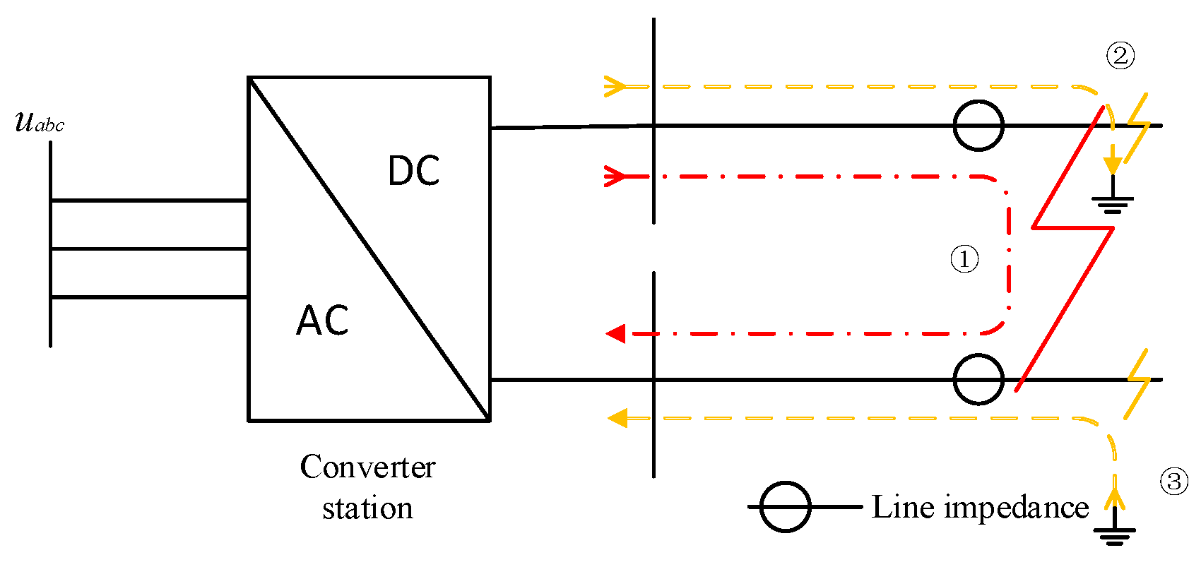
3.1. Unipolar Grounding Failure

In a DC system, the location of the fault point in a unipolar grounding fault does not affect the fault characteristics. However, the grounding configuration of the AC-side transformer and the neutral grounding mode of the DC-side capacitor have a significant impact on the fault characteristics. Considering economic and other factors, this paper focuses on the Δ/Yn configuration, specifically examining the case where the midpoint of the DC-side capacitor is directly grounded—this represents the bipolar wiring configuration using a single converter. The DC-side wiring configuration is illustrated in Figure 5.
When a unipolar grounding fault occurs, the ground voltage of the DC bus on the grounding side drops to zero. If the action of the lightning arrester is not considered, the non-fault pole-to-ground voltage will rise to twice the rated value. A discharge circuit will form between the fault point and the grounding point, leading to changes in the DC-side current. The ground point voltage offset causes a DC bias on the AC side, resulting in an increase in AC-side current due to the power feed into the fault point. Since the characteristics of positive and negative grounding faults are similar, this section focuses on the analysis of positive grounding faults.
Phase I of the DC system is in normal operation. When a single pole grounding fault occurs at time t1, it enters phase II. It is in the transient phase. It can be observed from Figure 6 that the DC voltage sag occurs at time t1. At the same time, the DC line flows through the short-circuit transient current, which will impact the thermal stability and dynamic stability of the electrical equipment. The grounding impedance is set as 4 Ω in the simulation process. Therefore, the amplitude of the transient current is small, only eight times that of the rated operation. Due to the function of the converter control system, the system enters the third stage, a stable state, at t2, and the DC voltage and current are restored to the rated value.

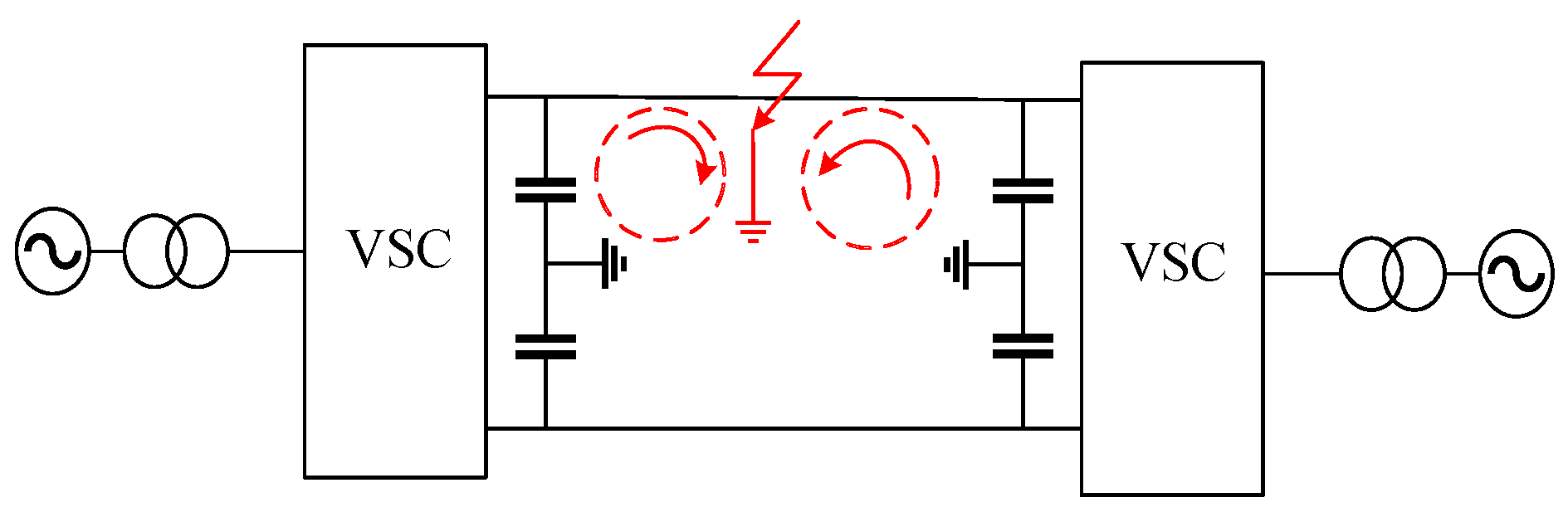
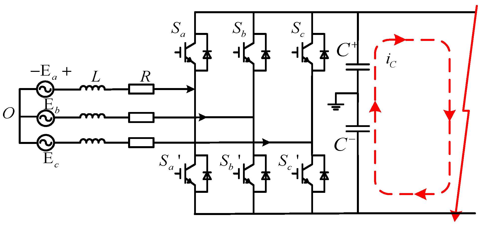
3.2. Interpole Short-Circuit Fault
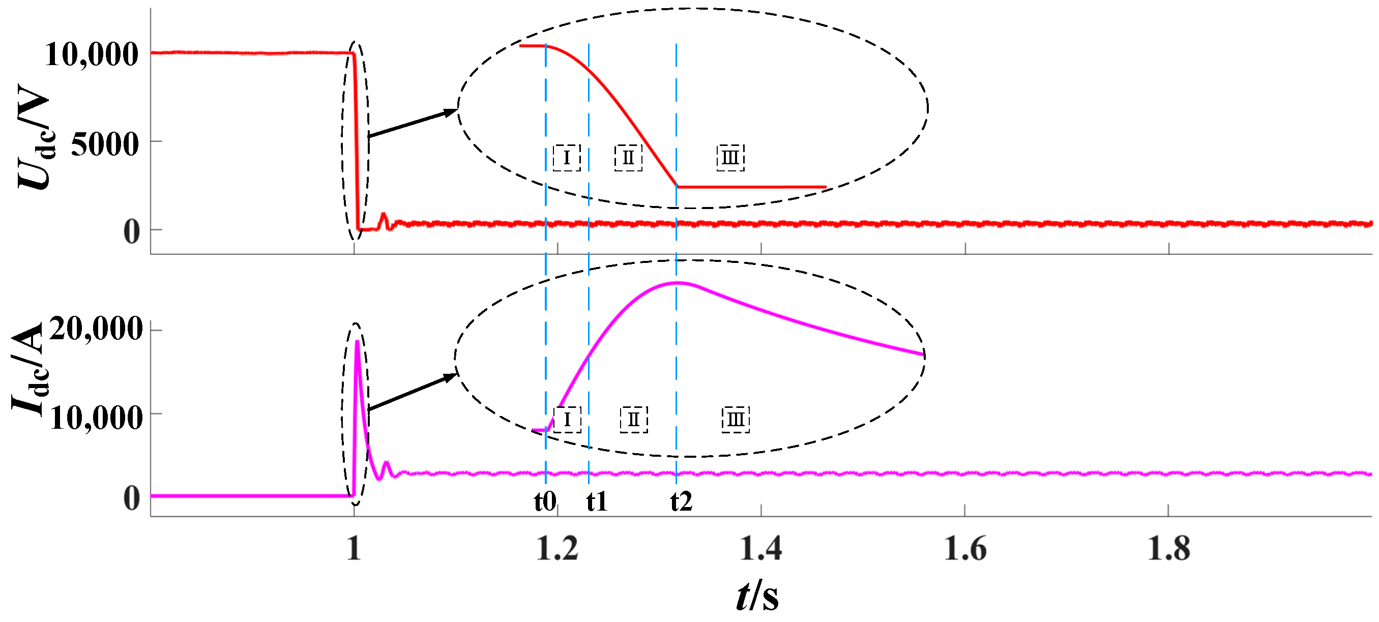
When an interpole short-circuit fault occurs in the DC distribution network, the interpole voltage of the DC line rapidly drops to zero, causing a sharp increase in DC current and interrupting the power transmission of the converter in the distribution network. The converter, composed of power electronic devices, is designed to protect itself by locking immediately when a fault is detected and the short-circuit current flowing through it exceeds the threshold. The circuit for the interpole short-circuit fault is illustrated in Figure 7.
The transient process after a short circuit occurs can be divided into three stages:
(1)
DC-side capacitive discharge stage: When a fault occurs, the DC-side capacitive voltage is higher than the AC-side line voltage. At this point, the capacitor supplies power to the fault circuit, while the AC side provides only the line reactance continuation current. During this phase, the capacitive voltage drops rapidly, and the fault current rises sharply.
(2)
Diode alternating uncontrolled rectification stage: As the DC-side capacitor voltage drops to the level of the AC-side line voltage, the AC side begins feeding current to the fault point through the uncontrolled rectifier bridge. The DC-side capacitor continues to discharge, causing the fault current to continue rising.
(3)
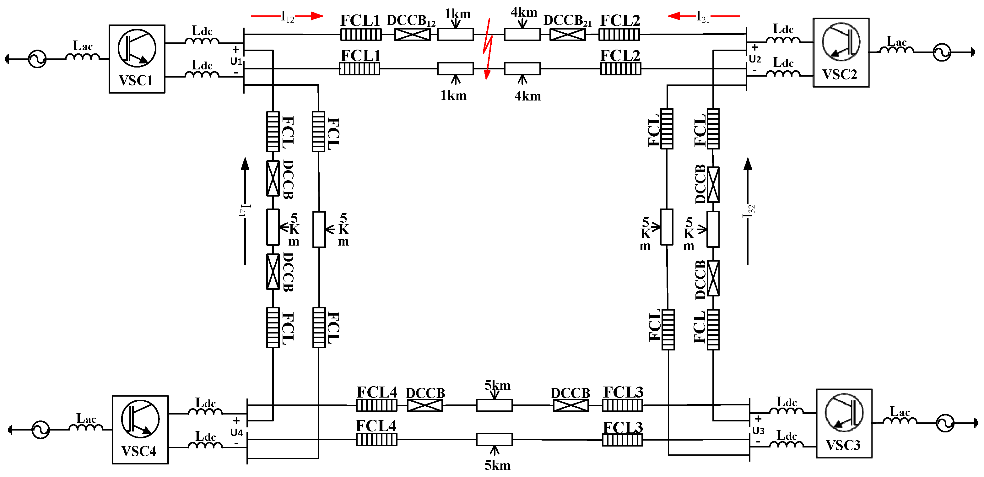
Full diode conduction stage: When the capacitor discharges to zero, all diodes turn on due to the back electromotive force generated by the DC-side reactance, leading to a decrease in the DC-side short-circuit current. The AC side essentially experiences a three-phase short-circuit fault, resulting in a rapid overcurrent. The converter then faces the impact of short-circuit currents on both the DC and AC sides, transitioning the system to the fault steady-state stage. The equivalent model of the fault phase is shown in the Figure 8, where RL and LL represent the equivalent resistance and inductance of the DC line, and Rs and Ls represent the equivalent resistance and inductance of the AC line.
When the short-circuit fault is in the capacitor discharge stage, the system behaves as a second-order circuit. The transient process during this stage can be described by Equation (14).
L L C d 2 u C d t 2 + R L C d u C d t + u C = 0
Generally, when R < 2 L C , the capacitance discharge stage is a second-order under-damped oscillation process, and the eigenvalue in Equation (15) is a pair of conjugate complex numbers.
λ 1 , 2 = R L L L ± R L 2 L L 2 1 L L C = σ ± j ω
where in the formula σ = R L 2 L L ,   ω = 1 L L C R L 2 L L 2 .
Assuming that the values of the DC voltage and DC current are U0 and I0, we can get the transient solutions of the capacitive voltage and fault current between poles as follows:
u c = A e σ t sin w t + θ i s = A C L L e σ t sin w t + θ β
where in the formula
A = U 0 2 + U 0 σ ω I 0 ω C 2 θ = arctan U 0 U 0 σ ω I 0 ω C β = arctan ω σ
From Equation (16), it is evident that the magnitude of the short-circuit current is related to the DC-side capacitance and line impedance. When the system capacity and voltage level remain constant, a larger capacitance results in more energy being stored prior to the fault, leading to a greater discharge current after the fault occurs. Conversely, a larger reactance requires less current to store the same amount of energy, thereby reducing the fault current. Similarly, with increased resistance, the fault current flowing through the resistance is reduced, which aligns with expected physical characteristics.
As shown in Figure 9, an interpole short-circuit fault is set in the DC line at t0. From t0 to t1, the DC-side capacitor discharges to the AC-side line voltage, and the current rises sharply, which is the first stage. From t1 to t2, the capacitor voltage drops to 0 and the short-circuit current continues to rise to the peak value (about 18 kA), which is the second stage of the fault. The first stage and second stage last about 3~4 ms. After t2, an RL first-order discharge circuit is formed, the short-circuit reactance is discharged through a freewheeling diode, and the fault current continues to decay to steady state, which is the third stage of fault.

4. Protection Configuration Based on Current Limiter

The current protection configuration for DC distribution networks remains imperfect, with most strategies still based on those used in AC systems and DC transmission systems, such as over-current, under-voltage, and voltage-current differential protection. No single type of protection can fully meet the requirements of the DC side, making it necessary to employ multiple protection methods in combination. Compared to the well-established AC protection devices, DC-side protection devices are still under development. In this paper, differential under-voltage protection is integrated into the control strategy of the flexible current limiter. This approach enables rapid fault monitoring, limits fault currents, and works in conjunction with mechanical DC circuit breakers to clear faults and prevent converter station locking, allowing the system to quickly resume operation after the fault is resolved.

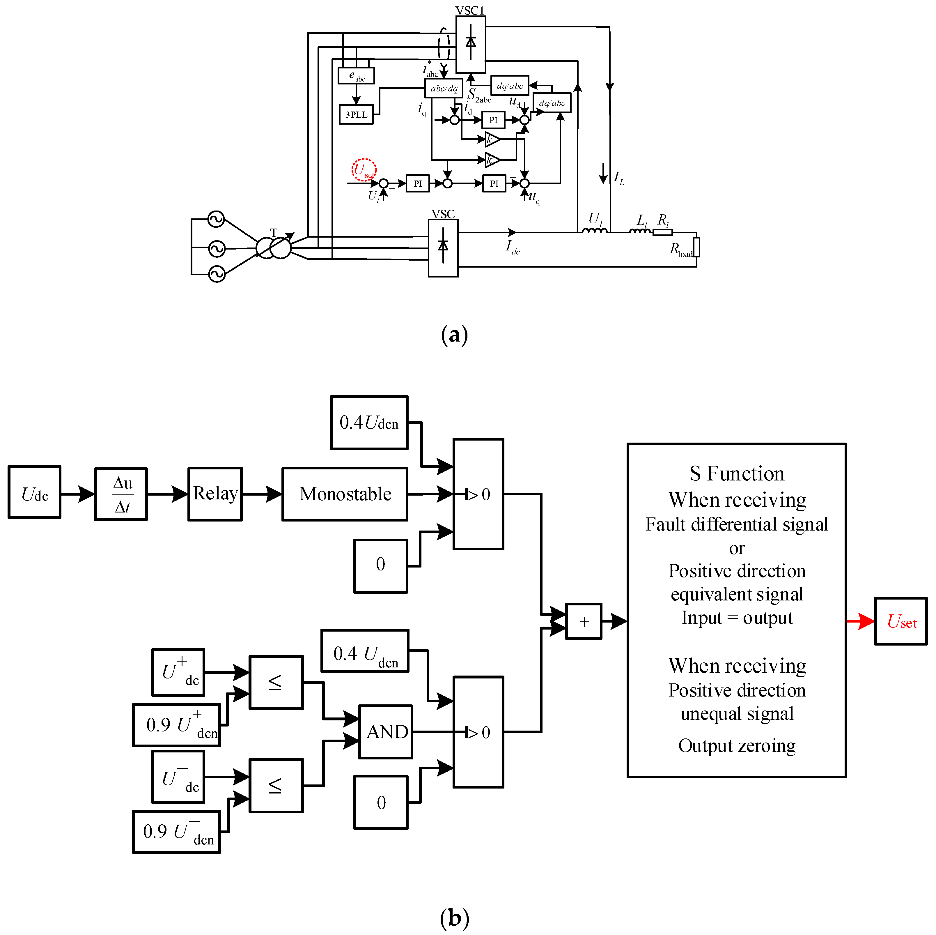
4.1. Current Limiter Control Strategy

The control scheme for the flexible current limiter is illustrated in Figure 10a, focusing solely on the control strategy for a single current limiter. The control target is the inductive voltage. In cascade mode, the voltage threshold of the current limiter is divided by the number of cascades. The flexible current limiter utilizes a constant voltage and constant current dual-loop control. Since the output side is an inductor, which acts as a reactive energy storage element, q-axis control is employed for the current loop.
Uset is the input in the current limiter control system and iq2 is the disturbance. As shown in Figure 10b, Uset needs to be set in the form of fault detection. Considering the speed and accuracy of detection, the current limiter can be started at the instant of the fault by using the combination of the voltage differential and under-voltage detection. The unipolar grounding fault and interpolar fault can be diagnosed quickly and the corresponding control input can be given as follows:
(1)
Monitoring Voltage Differential: The voltage differential between the poles on the DC side is monitored. When a fault occurs, this differential voltage rapidly spikes to its maximum value. The peak voltage differential between a pole fault and a unipolar grounding fault is observed, and the voltage differential trigger threshold is set using the Relay module in SIMULINK. Upon fault detection, the trigger signal outputs a value of 1, which is sustained for a certain duration via the Monostable module. Subsequently, 0.4 times the rated voltage is input to the current limiter, allowing the capacitive voltage to be clamped immediately to suppress short-term discharges that could lead to excessive short-circuit currents. Since factors such as fault type, fault location, and transition resistance can all influence the threshold setting, the influencing factors are studied under different operating conditions, and the minimum value within the identified range is used as the basis for setting the threshold [21].
(2)
Under-Voltage Judgment for Fault Type Determination: The voltage differential alone cannot reliably distinguish between a single pole grounding fault and an interpole short-circuit fault, so under-voltage detection is employed as the second stage for control input. Given the millisecond delay that occurs as the capacitor discharges to the set parameter value, this stage is executed simultaneously with the first stage. If only the positive or negative voltage does not exceed 0.9 times the rated value, it is determined that a single pole grounding fault has occurred on the DC side, and no further voltage is input to the current limiter. If both the positive and negative voltages do not exceed 0.9 times their respective rated values, it is judged that an interpole fault has occurred on the DC side. In this case, 0.4 times the rated voltage is again input to the current limiter, and the capacitor voltage is raised to 0.8 times the rated voltage, effectively limiting the fault current to near the rated current level. In the control strategy depicted in Figure 10b, when the current limiter is placed in the positive line, the inductance of the current limiter in the negative line does not change its voltage control mode; instead, the input value is adjusted to a negative value. The judgment threshold is set at 0.9 times the rated value in the second stage because voltage sag occurs when the specified voltage drops to 10–90% in the DC system.
(3)
Fault Expansion and Identification: When a fault occurs, it quickly propagates throughout the network, causing the flexible current limiter at each converter station outlet to detect and respond to the fault. Therefore, it is crucial to include fault identification for both in-zone and out-of-zone faults within the current limiter. The flexible current limiter must activate immediately upon fault detection. After determining whether the fault is inside or outside the zone, if it is an in-zone fault, the current limiter should continue operating. Conversely, if the fault is out-of-zone, the out-of-zone current limiter should be bypassed to prevent unnecessary energy loss. When the flexible current limiter receives a fault differential signal or an in-zone fault signal, the original inductive voltage input control remains unchanged to facilitate fault isolation. If an out-of-zone fault signal is received, the input control is cleared to avoid unnecessary operation of the out-of-zone flexible current limiter.

4.2. Internal and External Failure Judgment

When a short-circuit fault occurs on the DC side, the direction of the fault current in the DC-side line of any end converter is illustrated in Figure 11. Regardless of whether it is an interpole short-circuit fault or a unipolar ground fault, the fault pole current exhibits the following characteristics: if the positive pole line is the fault pole, the fault current flows from the bus to the line; if the negative pole line is the fault pole, the fault current flows from the line to the bus.
Thus, the positive direction for directional overcurrent protection in the positive pole lines is from bus to line, while for the negative pole lines, it is from line to bus. In the event of a unipolar grounding fault, only the directional overcurrent protection for the affected pole is triggered. Conversely, when an interpole short-circuit fault occurs, both levels of directional overcurrent protection are activated, allowing for the identification of the fault type and the specific pole where the failure occurred [22]. Based on this, a directional longitudinal protection strategy is established, as shown in the following figure.
Considering the cost-effectiveness of optical access in directional longitudinal protection, directional overcurrent protection is installed only on the positive pole of the DC side line. As illustrated in Figure 12, when an interpole short-circuit fault occurs on line 1, both Protection 12 and Protection 21 detect a positive pole overcurrent and transmit this signal to the opposite end via optical fiber. Due to the positive equivalence of the signals, it can be determined that the fault is located between converter station 1 and converter station 2, indicating an in-zone fault. Meanwhile, Protection 32, Protection 34, and Protection 41 also detect positive overcurrent, but they do not activate at their respective ends, and their optical signals do not match, indicating an out-of-zone fault. Once both in-zone and out-of-zone faults are identified, the circuit breaker operates to clear the fault in accordance with the current limiter protection principle.

4.3. Coordination Principle of Current Limiter and Circuit Breaker

Taking a single-side converter station as an example, and ignoring line impedance, both the positive and negative pole lines are equipped with current limiters and flat-wave reactors. A mechanical circuit breaker is installed only at the outlet of the positive pole lines. The configuration wiring is illustrated in Figure 13.
When an interpole short-circuit fault occurs in the line, if the DC side does not include an FCL and the fault is cleared solely by the DCCB, the loop voltage equation and the rate of change of the fault current are as follows:
U d c = U d c c b + 2 L d c d i d c d t d i d c d t = U d c U d c cb 2 L d c
When UdccbUdc, didc/dt < 0 is satisfied, and the surge arrester of the DCCB energy-consuming branch starts to operate because its residual voltage exceeds DC voltage, so the fault current starts to decrease.
After the current limiters are added, the loop voltage equation and the rate of change of the fault current are as follows:
U d c = U d c c b + 2 L d c d i d c d t + 2 U f c l d i d c d t = U d c c b + 2 U f c l U d c 2 L d c
At this moment, the voltage equation of the circuit changes and the condition of the fault current dropping changes accordingly. That is, Udccb + 2UfclUdc. The fault current drops when the voltage at both ends of the current limiter and the circuit breaker exceeds the voltage at the DC side. The voltage added at both ends of the current limiter is far beyond the residual voltage of the circuit breaker, so the residual voltage of the circuit breaker can be ignored after adding the current limiter, and the current-limiting effect is good. At the same time, the current limiter can limit both the fault current amplitude and the rising rate of the fault current. At the beginning of the fault, the converter station can be kept from being blocked by overcurrent and the requirement for DCCB interruption capability and speed are lowered.
When a failure occurs on the DC side, the circuit breaker is triggered upon meeting the specified conditions. Based on the protection strategies outlined in Section 3.1 and Section 3.2, the schematic diagram shown in Figure 14 is designed. A two-stage circuit breaker tripping signal is configured. The circuit breaker trips when the current limiter voltage exceeds 0.4 times the rated voltage and the directional longitudinal protection confirms a fault within the zone.
If a short-circuit fault occurs at the DC side, the current limiter acts instantaneously, and the directional pilot protection acts to judge the faults inside and outside the zone. After receiving the voltage fault signal of the current limiter and the fault signal inside and outside the zone, the mechanical DC circuit breaker acts selectively; that is, the circuit breakers are opened on both sides of the fault in the zone. When the flexible current limiter in the off-site converter station acts, the bypass operation is restored after receiving the off-site fault signal, so as to avoid the off-site circuit breaker action and energy loss of the current limiter, reduce the switching action times, and increase its service life. It can also reduce the scope of power failure, solve the problems of line overload after circuit breaker action outside the zone and converter station locking, and enhance the reliability of the DC-side power supply.

5. Simulation Validation

A simulation model of the DC distribution network is built using MATLAB/SIMULINK R2018b, with all four-terminal converter stations employing VSC topology. New flexible current limiters are installed only at the initial end of each pole line. The DC line impedance is set to r0 = 0.015 Ω/km and L0 = 0.1 mH/km. Other system structure and operation parameters are provided in Figure 15 and Table 1. An interpole short-circuit fault is introduced at the outlet of converter station 1 at 0.5 s. Based on this simulation model, the protection strategy proposed in this paper is analyzed and verified.

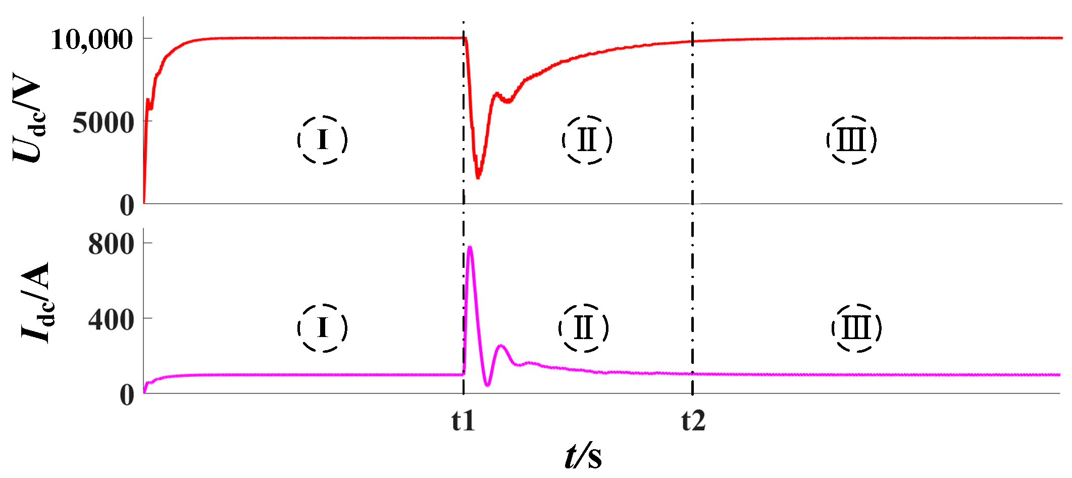
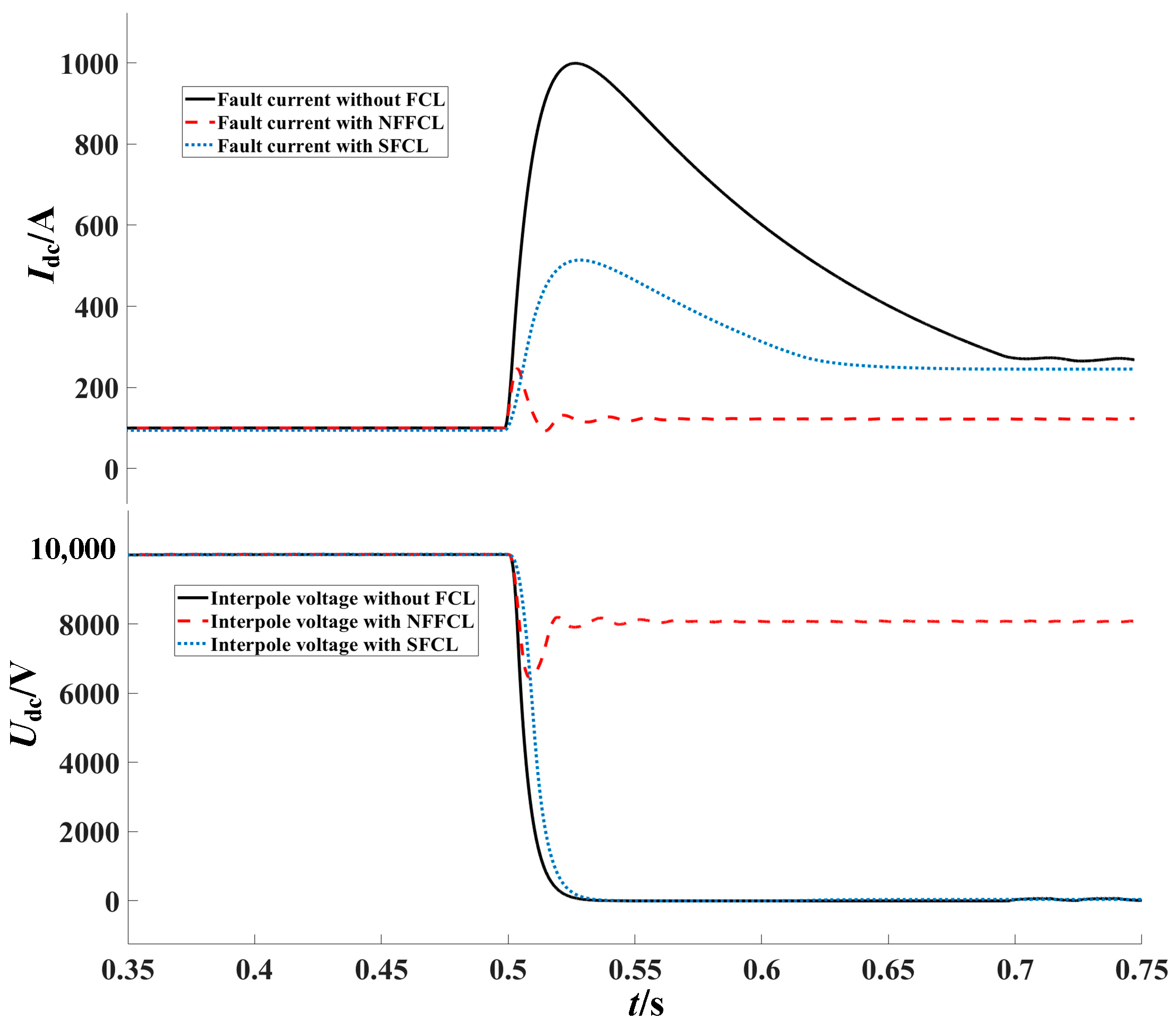
5.1. Action Effect with Current Limiter Only

This subsection simulates the fault state on one side of the converter station. An interpole short-circuit fault is introduced 1 km from the outlet of the converter station at 0.5 s. Upon detecting the fault signal, the flexible current limiter operates for 0.5 s. Additionally, an inductive superconducting current limiter is included separately to compare its effectiveness with that of the new current limiter. The simulation results are shown in Figure 16.
When a fault occurs, the interpole voltage on the DC side without a current limiter drops rapidly, and the fault current exceeds 1000 A, which is more than 10 times the normal operating level. This sudden surge causes significant impact damage to the power electronic components in the converter station and DC system. As the interpole voltage drops to zero, the fault current gradually decreases to a stable value, but it remains more than three times the rated level, leading to continuous energy loss and potential damage to equipment.
When an inductive superconducting current limiter is added, the system exhibits superconducting characteristics during normal operation, without affecting system performance. In the event of a short-circuit fault, external conditions cause the superconducting windings to quench, and the inductive characteristics limit both the rise rate and the amplitude of the fault current.
With the addition of the new type of current limiter, the fault current amplitude is reduced to less than three times the rated value, and is also lower than the amplitude achieved with the superconducting current limiter. The voltage between the poles begins to rise when it intersects the voltage rise curve of the current limiter, ultimately clamping at 8 kV. The new flexible current limiter allows for faster system recovery after the fault is cleared, with a remarkable current-limiting effect. The converter station threshold can be adjusted accordingly to ensure that the station does not block during a fault. Compared to the superconducting current limiter, the new flexible current limiter offers the advantages of a smaller size, lower cost, and superior current-limiting performance.

5.2. Fault Cleaning with Circuit Breaker Only

If only a mechanical DC breaker is installed on the DC side, without considering the flexible current limiter, the simulation results are presented in Figure 17.
The interpole short-circuit fault occurs at 0.5 s. The VSC1 and VSC2 are near the fault end. The interpole voltage drops to 0 V within 8 ms, and the fault currents I12 and I21 reach their peak values, both exceeding 1.7 kA. The bridge arm current of the converter station exceeds the self-protection threshold (3–5 times the rated current) within 2 ms and is blocked. When the interpole voltage drops to 0 V, the fault current begins to decrease. Other converter stations are away from the fault, so the fault current rises slowly and the amplitude is relatively small. I32 and I41 rise from −50 A to 0.6 kA and 1.3 kA after the short-circuit. At 3 ms after the fault occurs, the directional longitudinal protection monitors the fault signal in the zone to send out the braking instructions to DCCB12 and DCCB21. The mechanical switch brakes and burns the arc, and the transfer branch is put into operation to produce resonance zero crossing. At 15 ms after the fault occurs, the energy-consuming branch conducts and discharges energy. The voltage of each port restores to its rated state after the impact, and the fault current decreases accordingly. After the transient fluctuation, I12 and I21 disappear. I32 and I41 resume rated operating conditions. The time of the whole breaking process exceeds 18 ms.

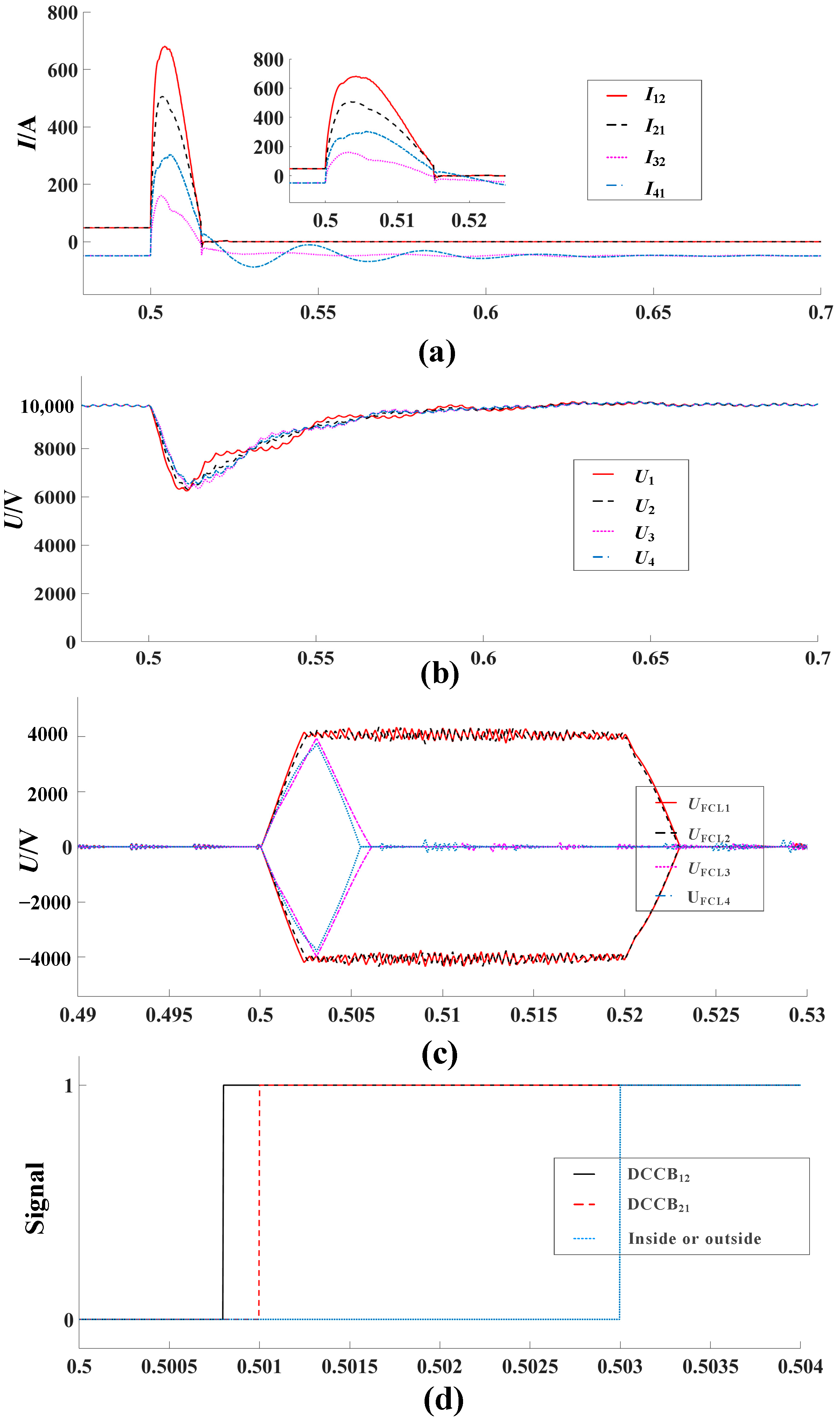
5.3. Fault Cleaning with Current Limiter and Circuit Breaker

Based on the protection mechanism outlined in Section 3, this section simulates and analyzes the fault removal process using the current limiter in conjunction with the circuit breaker.
The instantaneous flexible current limiter detects the fault differential signal and starts. It takes 2.5 ms for the voltage at both ends to rise to 8 kV. Therefore, the voltage at all converter stations drops to about 6.5 kV first. Due to the voltage clamp of the current limiter, the interpole voltage no longer drops and the fault current reaches its peak value (I12: 700 A, I21: 500 A, I32: 300 A, I41: 150 A). There is only 1/4 of the peak fault current when no current limiter is installed. From Figure 18b, it is known that the positive overcurrent signa is detected by DCCB12 and DCCB21 within 1 ms after the fault occurs, and the opposite signal is received after a delay of about 2 ms. It can be judged that the fault occurs between converter station 1 and converter station 2. The flexible current limiter at the outlets of converter stations 1 and 2 receives the fault signal in the zone and keeps the voltage at both ends unchanged. After receiving the out-of-zone fault signal, the flexible current limiter at the outlets of converter stations 3 and 4 controls the voltage and makes it drop to 0 at both ends to restore the bypass state. DCCB12 and DCCB21 then monitor the current limiter voltage and the in-the-zone fault signal, and then isolate the fault by action. The rest of the breakers do not operate, and the failure clearance cycle is about 20 ms. After isolation, the flexible current limiter resumes the bypass state, and the voltage and current of the four-terminal converter station resumes stabilization after oscillation. Since the overcurrent capacity of power electronic devices in the converter station is about 3–5 times the rated operating capacity, the threshold of the converter station can be set accordingly to avoid blocking of the converter station after failures.
During this process, the current limiter operates for only 20 milliseconds, effectively limiting the fault current and preventing the converter station from blocking. It clamps the outlet voltage of the converter station, allowing for a quick resumption of normal operation once the fault is cleared. This reduces the demands on the DCCB’s interruption speed and capacity, verifies the effectiveness of the protection strategy, and enhances the reliability of the DC-side power supply.

6. Conclusions

To address short-circuit faults in VSC–MTDC DC systems, a novel fault protection strategy is proposed, combining a flexible current limiter with a mechanical DC circuit breaker. This paper establishes a four-terminal ring DC distribution network model, further analyzes the coordination principles between the flexible current limiter and the DC circuit breaker, and presents a schematic diagram of the DC circuit breaker operation and fault-handling process. Simulations conducted on the MATLAB/SIMULINK platform validate the proposed protection strategies, leading to the following conclusions:
(1)
Bypass State During Normal Operation: The new flexible current limiter remains in a bypass state during normal operation, exerting no effect on the system. After a fault occurs, the current limiter clamps the voltage at its terminals through the AC-side rectifier, alters the DC-side discharge state, slows the rise of the fault current, reduces its amplitude, and lowers the requirements for the breaking speed and capacity of the DC circuit breaker.
(2)
High Flexibility and Adaptability: The flexible current limiter is composed of power electronic devices and their control modules, allowing it to be adjusted to handle different fault conditions with high flexibility. Its action time can be set according to the breaking speed of the DC-side circuit breaker. The flexible current limiter returns to the bypass state immediately after the fault is cleared, and depletes the fault energy stored in the current limiter inductance through an anti-magnetic flux device, thereby better preparing for subsequent faults.
(3)
Enhanced System Reliability: The proposed protection strategy, combining the flexible current limiter with the circuit breaker, enables the circuit breaker in the fault zone to operate independently during a short-circuit fault in the DC system. This approach minimizes the extent of power outages, prevents the collapse of the entire MTDC system, and limits the rise rate and amplitude of the fault current to avoid converter station blocking. As a result, the converter station can resume operation promptly after the fault is cleared, thereby improving the reliability of the system’s power supply.

Author Contributions

Investigation, resources, writing—review, supervision, L.C.; supervision, visualization, writing—review, J.L.; supervision, visualization, resources, J.C.; supervision, visualization, resources, F.Z.; supervision, visualization, resources, N.L. All authors have read and agreed to the published version of the manuscript.

Funding

Project supported by Natural Science Foundation of China (52167010).

Data Availability Statement

The original contributions presented in the study are included in the article, further inquiries can be directed to the corresponding author.

Conflicts of Interest

L.C. was employed by China Energy Construction Corporation and J.C. was employed by State Grid Lanzhou Power Supply Company. The remaining authors declare that the research was conducted in the absence of any commercial or financial relationships that could be construed as a potential conflict of interest.

References

  1. Fan, Y.; Chi, Y.; Li, Y.; Wang, Z.; Liu, H.; Liu, W.; Li, X. Key technologies for medium and low voltage DC distribution system. Glob. Energy Interconnect. 2021, 4, 91–103. [Google Scholar] [CrossRef]
  2. Perera, C.; Salmon, J.; Kish, G.J. Multiport Converter with Independent Control of AC and DC Power Flows for Bipolar DC Distribution. IEEE Trans. Power Electron. 2021, 36, 3473–3485. [Google Scholar] [CrossRef]
  3. Feng, X.; Xiong, Q.; Wardell, D.; Gattozzi, A.L.; Strank, S.M.; Hebner, R.E. Extra-Fast DC distribution system protection for future energy systems. IEEE Trans. Ind. Appl. 2019, 55, 3421–3430. [Google Scholar] [CrossRef]
  4. Muniappan, M. A comprehensive review of DC fault protection methods in HVDC transmission systems. Prot. Control. Mod. Power Syst. 2021, 6, 1. [Google Scholar] [CrossRef]
  5. Mirsaeidi, S.; Dong, X.; Shi, S.; Wang, B. AC and DC microgrids: A review on protection issues and approaches. J. Electr. Eng. Technol. 2017, 12, 2089–2098. [Google Scholar]
  6. Faazila Fathima, S.; Premalatha, L. Protection Strategies for AC and DC Microgrid–A Review of Protection Methods Adopted in Recent Decade. IETE J. Res. 2021, 69, 6573–6589. [Google Scholar] [CrossRef]
  7. He, Y.; Zheng, X.; Tai, N.; Wang, J.; Nadeem, M.H.; Liu, J. A DC Line Protection Scheme for MMC-Based DC Grids Based on AC/DC Transient Information. IEEE Trans. Power Deliv. 2020, 35, 2800–2811. [Google Scholar] [CrossRef]
  8. Bayati, N.; Hajizadeh, A.; Soltani, M. Protection in DC microgrids: A comparative review. IET Smart Grid 2018, 1, 66–75. [Google Scholar] [CrossRef]
  9. Li, C.; Rakhra, P.; Norman, P.J.; Burt, G.M.; Clarkson, P. Multi-Sample Differential Protection Scheme in DC Microgrids. IEEE J. Emerg. Sel. Top. Power Electron. 2021, 9, 2560–2573. [Google Scholar] [CrossRef]
  10. Chandra, A.; Singh, G.K.; Pant, V. Protection techniques for DC microgrid—A review. Electr. Power Syst. Res. 2020, 187, 106439. [Google Scholar] [CrossRef]
  11. Xiang, W.; Yang, S.; Xu, L.; Zhang, J.; Lin, W.; Wen, J. A Transient Voltage-Based DC Fault Line Protection Scheme for MMC-Based DC Grid Embedding DC Breakers. IEEE Trans. Power Deliv. 2019, 34, 334–345. [Google Scholar] [CrossRef]
  12. Javed, W.; Chen, D.; Farrag, M.E.; Xu, Y. System configuration, fault detection, location, isolation and restoration: A review on LVDC microgrid protections. Energies 2019, 12, 1001. [Google Scholar] [CrossRef]
  13. Li, Y.; Liang, S.; Chen, X.; Chai, X.; Sun, C.; Zhu, H. Line protection scheme for DC distribution grids. Dianli Xitong Baohu Yu Kongzhi/Power Syst. Prot. Control. 2019, 47, 136–144. [Google Scholar]
  14. Jovcic, D.; Lin, W.; Nguefeu, S.; Saad, H. Low-energy protection system for DC grids based on full-bridge MMC converters. IEEE Trans. Power Deliv. 2018, 33, 1934–1943. [Google Scholar] [CrossRef]
  15. Yang, S.; Xiang, W.; Wen, J. Analysis of impact of grounding-pole current-limiting reactor on fault detection of MMC based DC grids. In Proceedings of the 8th Renewable Power Generation Conference (RPG 2019), Shanghai, China, 24–25 October 2019; IET Conference Publications: London, UK, 2019. [Google Scholar] [CrossRef]
  16. Gao, P.; Zheng, X.; Chao, C.; Tai, N.; Yang, Z.; Wang, J. Protection for Multi-terminal Flexible DC Transmission Lines Based on Boundary Transient Energy. Dianli Xitong Zidonghua/Autom. Electr. Power Syst. 2021, 45, 171–179. [Google Scholar]
  17. Zhu, S.; Zhao, C.; Xu, J. Time-sequence Coordination of Protection in DC Grid with Multi-type Fault Current Limiting Devices. Dianli Xitong Zidonghua/Autom. Electr. Power Syst. 2019, 43, 195–207. [Google Scholar]
  18. Yang, Q.; le Blond, S.; Liang, F.; Yuan, W.; Zhang, M.; Li, J. Design and Application of Superconducting Fault Current Limiter in a Multiterminal HVDC System. IEEE Trans. Appl. Supercond. 2017, 27, 3800805. [Google Scholar] [CrossRef]
  19. Xiang, B.; Gao, L.; Liu, Z.; Geng, Y.; Wang, J. Short-circuit fault current-limiting characteristics of a resistive-type superconducting fault current limiter in DC grids. Supercond. Sci. Technol. 2020, 33, 024005. [Google Scholar] [CrossRef]
  20. Zheng, F.; Zhang, J.; Lin, J.; Deng, C.; Huang, J. A Novel Flexible Fault Current Limiter for DC Distribution Applications. IEEE Trans. Smart Grid 2022, 13, 1049–1060. [Google Scholar] [CrossRef]
  21. Gao, B.; Dong, P.; Liu, X.; Zhang, X.; Zhang, Y.; Ma, Y.; Zhao, S. Research of HVDC transmission line differential under-voltage protection characteristics and value setting. Dianwang Jishu/Power Syst. Technol. 2015, 39, 2303–2311. [Google Scholar]
  22. Li, B.; He, J.; Li, Y.; Li, B.; Wen, W. High-speed directional pilot protection for MVDC distribution systems. Int. J. Electr. Power Energy Syst. 2020, 121, 106141. [Google Scholar] [CrossRef]
Figure 1. VSC converter topology.
Symmetry 16 01275 g001
Figure 2. Structure of mechanical DC circuit breaker.
Symmetry 16 01275 g002
Figure 3. Structure of flexible current limiter.
Symmetry 16 01275 g003
Figure 4. Closed core structure.
Symmetry 16 01275 g004
Figure 5. Single pole ground fault under bipolar connection.
Symmetry 16 01275 g005
Figure 6. Single pole grounding fault.
Symmetry 16 01275 g006
Figure 7. Interpole short-circuit fault circuit.
Symmetry 16 01275 g007
Figure 8. Transient process of interpole short-circuit fault.
Symmetry 16 01275 g008
Figure 9. Interpole short-circuit fault.
Symmetry 16 01275 g009
Figure 10. Current limiter control strategy. (a) Current limiter rectifier control; (b) current limiter voltage input signal control mode.
Symmetry 16 01275 g010
Figure 11. DC fault current direction. ①—Direction of short-circuit current between poles; ②—direction of short-circuit current for positive ground; and ③—direction of short-circuit current for negative grounding.
Symmetry 16 01275 g011
Figure 12. Schematic diagram of internal and external faults at the DC side.
Symmetry 16 01275 g012
Figure 13. Configuration wiring of single side converter station.
Symmetry 16 01275 g013
Figure 14. Operation principle block diagram of the DC circuit breaker.
Symmetry 16 01275 g014
Figure 15. System structure of the four-terminal DC distribution network.
Symmetry 16 01275 g015
Figure 16. Voltage and current comparison with an infinite current transformer.
Symmetry 16 01275 g016
Figure 17. Failure cleanup with only DCCB.
Symmetry 16 01275 g017
Figure 18. Port parameters under short-circuit fault. (a) Converter station outlet current; (b) Converter station voltage between electrodes; (c) Voltage at both ends of the flexible current limiter; (d) Fault detection signal inside and outside the area.
Symmetry 16 01275 g018
Table 1. System parameters of the four-terminal DC distribution network.
VSC1VSC2VSC3VSC4
Rated capacity of converter station (MV·A)20101010
DC-side voltage/kV±5±5±5±5
DC-side capacitance value/mF4222
AC-side reactance value/mH50707070
Flat-wave reactor value/mH20202020
Control modeU, QP, QP, QP, Q
Disclaimer/Publisher’s Note: The statements, opinions and data contained in all publications are solely those of the individual author(s) and contributor(s) and not of MDPI and/or the editor(s). MDPI and/or the editor(s) disclaim responsibility for any injury to people or property resulting from any ideas, methods, instructions or products referred to in the content.

