Article

An Approach to Accurately Identifying Binders in Historic Mortars by the Combination of Microscopic and Microanalytical Techniques

1
HERCULES Laboratory, University of Évora, Largo Marquês de Marialva, 8, 7000-809 Évora, Portugal
2
UNIARQ, Archaeology Center of the University of Lisbon, Faculty of Letters, Alameda da Universidade, 1600-214 Lisbon, Portugal
3
Materials Department, LNEC, National Laboratory for Civil Engineering, Avenida do Brasil, 101, 1700-066 Lisbon, Portugal
4
Buildings Department, LNEC, National Laboratory for Civil Engineering, Avenida do Brasil, 101, 1700-066 Lisbon, Portugal
5
Geosciences Department, Colégio Luís António Verney, University of Évora, Rua Romão Ramalho, 59, 7000-671 Évora, Portugal
*
Author to whom correspondence should be addressed.
Minerals 2024, 14(8), 844; https://doi.org/10.3390/min14080844
Submission received: 10 July 2024 / Revised: 2 August 2024 / Accepted: 19 August 2024 / Published: 21 August 2024

Abstract

:
Mortars are among the most important materials in building construction. They are generally obtained by mixing aggregates with an inorganic binder. The identification of mortar constituents, particularly the binder type in historic buildings, is one of the essential aspects of building conservation, considering that the new conservation materials must be chemically, mechanically, and physically compatible with the old masonries. Among other techniques used to characterise binders, those related to optical and electronic microscopy are particularly important. Microscopy and combined techniques may be the key to this identification since the classic mineralogical and chemical-based identification approaches are not conclusive enough in investigating the types of hydraulic binders in mortars. This work presents an analysis procedure to identify mortar binders by combining EDS microanalysis and petrography. Mortar samples of known composition were used as a reference for analyzing mortars from historic buildings. The proposed methodology made it possible to identify the type of binder or a mixture of binders based on the identification of the binder features by petrography together with analysis of the chemical composition of the paste by X-ray microanalysis under a scanning electron microscope.

1. Introduction

Mortars are an essential part of the construction of built structures and have become more sophisticated over time, evolving in close connection with manufacturing technologies and construction techniques.
Mortars have various functions, such as rendering walls, repointing and joints, covering and bedding masonry elements, or bonding ceramic tiles.
Over time, the functions assigned to mortars have mostly stayed the same. They are generally composite materials technologically characterized by a mixture of aggregates with one or more types of binders, water, and additions. The most typical traditional binders could be based on clay, lime, and gypsum [1,2]. The innovative changes were related to the binders’ production technology, the mix’s formulation, and the incorporation of different materials that granted characteristics or performances that increased durability and strength. Regarding innovation in formulation, pozzolanic materials in Roman times stand out, namely replacing volcanic ashes with crushed or powdered ceramic fragments when the former was unavailable [3]. Mortars with ceramic fragments (cocciopesto) were preferred for water-bearing structures and moisture protection, often used in baths, canals, and aqueducts [3,4,5,6,7,8]. This innovation in mortar production aligns with modern sustainability and recycling themes. Studies [9,10] indicate that the ceramic fragments in cocciopesto differ in optical activity (birefringence), petrographic characteristics, and texture. This diversity implies that they were made from recycled materials from various ceramic productions, potentially representing one of the earliest instances of reuse and recycling in history [9,10].
There have been considerable changes throughout history in the manufacture of binders, especially since the 18th century, when technologies were discovered that made it possible to produce various types of hydraulic binders and expand the application of hydraulic mortars in construction.
Lime mortars can be divided into air lime mortars and hydraulic lime mortars, depending on whether air or hydraulic lime is used. Compounds can also be incorporated to make mortars hydraulic (e.g., natural or artificial pozzolans, crushed bricks, silica, and amorphous alumina) even without a hydraulic binder.
Hydraulic mortars can also be based on natural or artificial types of cement, such as Portland cement. Hydraulic lime is obtained from a burnt natural rock (siliceous/argillaceous limestone or calcareous marl) below the sintering temperature (800–1200 °C). It must contain enough free CaO to be slaked with water and be capable of setting under water. The calcined product must contain a minimum amount of free CaO to reduce the entire mass to a powder when slaked [1].
Natural cement, also known as Roman cement, was patented by James Parker in England in 1796 [11]; its hydraulicity is due to the raw material used. Parker used calcareous nodules (septarian nodules) found in the London clay beds on the Isle of Sheppey, England, and calcined them in his domestic fire. He then ground the resulting clinker and mixed it with water. This process led to the creation of a quick-drying, nut-brown-colored cement [11,12,13].
Despite implied links to the Roman binders, Parker’s ‘Roman cement’ was a proper hydraulic cement very different from the hydraulic binders used by the Romans in which pozzolanic materials, not cementitious in themselves, had combined with lime in the presence of water to form insoluble compounds possessing cementing properties [12].
The standardization of technological processes has led to the manufacture of various types of binders with characteristics that are now known in more recent historical periods. Air lime can currently be classified according to standard EN 459-1:2015 [14], which divides lime into calcium (CL) or dolomitic (DL), considering its chemical composition. The same standard also establishes the classification of natural hydraulic lime (NHL), which differs chemically and mineralogically, leading to different compressive strength ranges.
Air lime is divided into fat and lean. Fat air lime is derived from almost pure limestone with at least 99% carbonate content. Lean (generally greyish) is derived from limestones with clay and other impurity contents between 1 and 5% [15].
Roman cement is a type of cement made from marl or septaria that contains 25% or more clay. This cement is considered “natural” because all the necessary components, such as lime, silica, and alumina, are found in a single source material, unlike Portland cement, which is made from different sources [13].
Although they are natural hydraulic binders, according to Kozłowski (2010) [12], natural cements are distinct from hydraulic limes in that they have low levels of free lime, which means they need to be ground instead of slaked. They are also different from Portland cements due to their different chemical composition, resulting in significantly lower calcination temperatures. The primary hydraulic phase in natural cements is C2S (dicalcium silicate or belite), whereas in ordinary Portland cement, it is C3S (tricalcium silicate or alite).
Although both Roman cement and natural hydraulic lime are calcined at low temperatures, they differ in that the cement hardens quickly, usually in less than 15 min. Both materials contain substantial amounts of belite and have a prolonged strength development profile. Roman cements can be differentiated from Portland cements by the presence of residual quartz and calcite and the absence, or residual content, of tricalcium silicate (C3S—alite), which is responsible for the substantial strength development in Portland cements [12].
Historical cementitious or highly hydraulic mortar binders exhibit a lesser degree of chemical definition than their contemporary counterparts. Consequently, comprehensive characterization of these binders within mortar specimens requires meticulous examination of the residual unhydrated particles within their structural framework. This endeavor is optimally facilitated through microscopic techniques, potentially augmented by chemical point analysis [16].
As some authors recognize [16,17,18], instrumental bulk analyses such as X-ray diffraction or chemical analysis are less capable of tracing the binder constituents than imaging or microscopical analytical tools.
This study proves innovative as it combines elementary chemical analyses with polarized light microscopy. It aims to group different mortar types according to their binders, distinguishing mortars made with hydraulic binders, namely 20th-century Portland cement, natural cement (from the late 19th century) and NHL. Although NHL mortars were widely used in construction until the 19th century, the mass production of Portland cement, combined with its performance, likely meant that hydraulic cementitious binders were the choice of binders in the 20th century buildings studied. In order to cover the various types of binders, NHL mortar samples produced in the laboratory were also investigated.
It should also be mentioned that the ageing of hydraulic binders, such as Portland cement involves several chemical processes that can affect their long-term durability and performance. One critical process is carbonation, which involves the reaction of carbon dioxide (CO2) from the air with the hydrated phases of the binder. The carbonation leads to calcium carbonate (CaCO3) formation and subsequent decalcification, where calcium ions are leached out of the material [19]. Thus, the Si/Ca and Al/Ca ratios can increase with time.
Since the main factors in obtaining the various types of mortar binders depend on the raw material and the temperature of calcination and/or sintering, the latter depending on the manufacturing technology available at the time. The applied methodology and the results obtained can be used to characterize mortars from other historical periods.
The aspects identified above are even more critical regarding material compatibility. This greatly impacts conservation and restoration interventions, which must respect the original materials’ physical, mechanical, and chemical characteristics [20,21] as much as possible to prevent future decay phenomena.

2. Materials and Methods

2.1. Samples and Analytical Background

Fifty-one samples were investigated from buildings constructed throughout the 20th century in Lisbon (Portugal), whose characteristics and sampling setup can be consulted elsewhere [22], as part of a thoroughly characterization study. Additionally, two natural cement samples were analyzed from cast decorative elements in Barcelona buildings (Spain), built between the end of the 19th century and the beginning of the 20th century [23].
Table 1 presents the type of binder and the binder-to-aggregate (b:a) ratio of the analyzed render and plaster samples and their construction or application period. The b:a ratio was relevant to investigate if this ratio would impact the chemical analysis results.
For lime mortars, the b:a ratio was calculated using the insoluble residue (IR) values obtained by wet chemical analysis and the CO2 content obtained by thermogravimetry (TGA-DTA) [22]. The insoluble residue (IR) corresponds to siliceous aggregate content after acid dissolution of the binder by a nitric acid solution. The samples are previously ground until they completely pass through a 106 μm sieve. The samples are quartered until 2g is obtained and then etched with HNO3 until the release of CO2 stops. The IR is then determined by gravimetry. In contrast, the binder content was calculated from the CO2 content (obtained by TGA-DTA in the weight loss range between 500–900 °C). The amount of CO2 correspond to the amount of calcium carbonate in the binder, which can then be converted to Ca(OH)2 [24], considering that all of the CO2 came from the decomposition of carbonated lime (CaCO3). For cementitious mortars, regardless of whether they contain other binders, the Portland cement content was obtained according to Arliguie’s (2007) method [25]. This method does not consider the use of mineral additions in the binder, so the calculations of Portland cement as a binder were performed by default.
The b:a ratio was obtained by point counting in thin sections for mortars with carbonate aggregates, according to RILEM Technical Committee TC167-COM recommendations [26].
The samples analyzed have the following binders: air lime (AL), natural hydraulic lime (NHL), natural cement (NC), ordinary Portland cement (OPC), Portland composite cement with mineral additions, like fly ash (FA) or ground granulated blast furnace slags (GGBS), and blended air lime and Portland cement (with OPC or white Portland cement—WPC). To investigate the different types of binders, a methodology involving a series of complementary analytical procedures was previously used, namely mineralogical investigation by XRD to characterize the overall and the binder-rich fraction and microstructural and optical microscopy analysis (SEM-EDS and petrography) in accordance with specialized literature to identify the key features of each type of binder [16,24,25,26,27,28,29].
In addition, mortar specimens formulated in the laboratory were also analyzed. These specimens were used as a control and a reference for elemental analysis. They were mainly formulated in the laboratory for previous research work and used in the present context [30,31,32]. Their formulations can be found in Table 2.

2.2. SEM-EDS and Principal Component Analysis

Scanning electron microscopy with energy dispersive X-ray spectrometry (SEM-EDS) was performed in a TESCAN MIRA 3 field emission microscope (Tescan Group, a. s., Brno—Kohoutovice, Czech Republic) combined with a BRUKER XFlash 6|30 EDS system (Bruker Corporation, Billerica, MA, USA). Polished flat specimens or thin sections from each mortar sample were prepared as described in the following section and were analyzed in backscattered electron mode, with a chamber pressure of 20 Pa and 20 kV accelerating voltage, with an absorption current circa 300 pA, using a magnification over 500× in paste areas.
Over 50 EDS spot areas (<10 μm2) were captured in each specimen, being the oxygen calculated by stoichiometry [33] and rejecting the values for Al/Si and Ca/Si atomic ratios higher than 10% of the coefficient of variation.
Principal component analysis (PCA) was performed using the results of the EDS analysis processed with OriginPro 9.0 software. PCA was performed to test and explore a mortar type’s clustering structure to help understand how clusters are distributed and whether they are well-separated or overlapping.

2.3. Optical Microscopy—Petrography

The thin section technique, a significant advancement in the field of petrography, was developed by 19th-century geologists. It initially aided in studying rocks and minerals, and its application later expanded to include construction materials like concrete and mortar by the 1920s [34]. Today, this versatile technique is widely employed across various materials, including brittle substances like concrete and mortar. The samples were stabilized through embedding in epoxy resin, enabling cutting and grinding to a final thickness of 20–30 μm.
Petrographic observations were then conducted on thin sections using an Olympus BX60 (Tokyo, Japan) petrographic microscope featuring magnification lenses of 5×, 10×, 20×, and 40×. Residues within the mortar matrix necessitate microscopic tools to pinpoint the binder type [27], especially when distinguishing between the various hydraulic binders, which is why it became essential to apply this technique. It should be noted that petrography was only used to distinguish between mortars with hydraulic binders whenever the SEM-EDS methodology was inconclusive. Both methods (SEM-EDS and petrography) are complementary but should be used together.

3. Results and Discussion

3.1. SEM—EDS and Principal Component Analysis

EDS analysis and observations in backscattered mode were performed to mark out and group each type of binder used in terms of chemical composition. The analyses helped detect whether there were significant chemical differences between blended air lime Portland cement mortars and the other mortar types, considering the variability in the mix-design properties that could influence the composition, namely the binder-to-aggregate ratio.
The chemical compositions obtained by EDS were used to calculate the Al/Ca and Si/Ca atomic ratios (Table 3).
The hydraulicity of binders is highly variable [35] and was first determined by Louis Vicat (1818) [36] using the Hydraulicity Index. Vicat synthesized the available knowledge and directly linked hydraulicity to the SiO2 and Al2O3 content. Subsequently, Eckel (2005) [37] introduced a novel index known as the Cementation Index. This index incorporates the influence of Fe2O3 and MgO on hydraulicity, presuming that all available SiO2 combines with CaO to produce C3S (Ca3SiO5) and that all Al2O3 combines to produce C3A (Ca3Al2O6). MgO is equated with CaO and Fe2O3 with Al2O3.
Nevertheless, this representation oversimplifies matters, as the mineralogy of hydraulic binders is more intricate than assumed [35]. The combustion temperature and duration indirectly influence the hydraulic characteristics, impacting the product’s mineralogy [38]. Despite acknowledging this observation, the selection of Al/Ca and Si/Ca elemental atomic ratios is rationalized due to the importance of the CaO–SiO2–Al2O3 system in evaluating the hydraulicity of mortars and binders, as evidenced by Mertens et al. 2008 [39], who scrutinized the composition of historical calcareous hydraulic binders within that chemical system.
Figure 1 shows an expected increase in hydraulic binders’ Si/Ca ratio, while the Al/Ca ratio is variable within the specified clusters. Although there are few laboratory test specimens, finding a chemical composition concordance between them and the other analyzed samples is possible. The only discrepancy found is the composition of the mixed mortars, which has such a dispersion that some compositions are encompassed in the cluster of cement mortars or even at the limit between natural cement and NHL mortars.
The presence of limestone filler in the paste of stone-imitating mortars reduced both ratios, as can be seen in cluster E1. Cluster E2 stands out from the others as it includes binders with mineral or pozzolanic additions rich in silica or alumina.
For comparative purposes and to attempt to improve the discrimination of this group of samples, principal component analysis (Figure 2) was carried out considering the analytical results presented in Table 3. The by-mixed mortars have high dispersion, and their cluster overlaps with the PC cluster. However, the air lime and Portland cement mortars were distinctively separated. A plot in the plane of the two principal components (PC1 and PC2) is shown in Figure 3. PC1 explains 43.73% of the variation and is controlled in the positive sense primarily by the contents in O, Si, Al, and Fe (somehow related to hydraulicity, which depends primarily on the clay content of the raw material) and in the opposite sense by the content in Ca (air lime binder’s main element) and Cl. PC2 explains 16.38% of the variation and is controlled in the positive sense primarily by the contents in Ca and Na; in the opposite sense, no element has influence (as seen in the loadings plot of Figure 3). Although Cl may derive from the composition of the epoxy resin, which cannot be proved for all the analyzed samples, the influence of Na (PC2) raises questions regarding the contamination by salts and their possible influence on the analytical results of the binders.
Almeida et al. (2023) [22] characterized the binder-rich fraction by X-ray diffractometry (XRD) of the Lisbon mortars, which was obtained by extracting the fines, passing through a 106 μm sieve directly from the bulk mortar. They also obtained the overall fraction corresponding to the samples as collected, obtained by crushing and grinding to pass through a 106 μm sieve and then analyzed by XRD. XRD detected Halite (NaCl) in samples CVT1C, CVT3B, AR49-7B, and AR49-11B (Figure 4), though only AR49-7B and AR49-11B are influenced by both contents. Nonetheless, sodium may be derived from the sodium feldspars (i.e., albite) from the aggregates, as the same authors stated elsewhere [22] (see Figure 4).
Similarly to Figure 1, Figure 2 shows a cluster (E1) of samples with mineral additions and pozzolanic material and another, cluster E2, which refers to stone imitating mortars with limestone filler. As an outlier, sample CBP7B has a high influence of sulfur derived from gypsum in the binder [22]. Figure 5 shows a detail of the binder paste of this sample, confirming the presence of gypsum (needle-shaped crystals), in which can be seen the distribution of the elements Ca and S. This sample stands out from the others since it is a supporting mortar of a crown molding plaster element [22]. The incorporation of gypsum must, therefore, be related to the construction technique.
According to the EDS results (see Figure 1 and Figure 2), mortars in which lime has been mixed with Portland cement are chemically similar to cement mortars. The plot in Figure 6 shows no tendency for the Si/Ca ratio to increase as the binder content (in this case, Portland cement) increases. This finding has significant implications, as it suggests that the Portland cement content in the mix does not considerably influence the chemistry of the paste, which can be explained by the fact that the pastes were poorly mixed or there may be an influence from the composition of the raw materials from different origins to contribute to this compositional variability.

3.2. Optical Microscopy—Petrography

Considering the elemental analysis results, more specifically the Si/Ca ratio vs. Al/Ca ratio, there is a noticeable overlap between groups B (NHL mortars) and D (natural cement mortars) and between C (blended air lime Portland cement mortars), E (Portland cement mortars), and E1 (Portland cement stone imitating mortars with limestone filler). A complementary approach is needed to identify the binders unequivocally. A literature review shows that each type of binder has its characteristics with its compounds. Much of the identification using optical microscopy is carried out to find residues resulting from the manufacturing process, i.e., ‘fossil’ traces of the raw material, residues (or ‘relicts’) of the binder that have not produced chemical and physical reactions, or even neoformation products resulting from interaction with the binder matrix.
Air lime, which has been extensively studied, is often characterized by the presence of lumps. Lime lumps are fragments macroscopically showing a whitish color and sometimes an inconsistent appearance [40,41,42,43]. Among several authors, Cantisani et al. 2022 [42], observing the thin section of lumps under a polarized light microscope, stated that the presence of lime lumps is fundamental to recognize the lime binder nature, allowing information about the stone used to produce lime. According to Pavia and Caro (2007) [28], binder properties, including reactivity, shrinkage, cohesion, and fineness, can also be analyzed with petrographic microscopy, providing essential clues on lime calcination and slaking. The same authors point out that the accumulation of lime lumps often appears fractured under the microscope because pure calcium lime is a non-hydraulic binder with a high retraction coefficient. Other authors state that the presence of lime lumps can indicate incomplete calcination [44], poor mixing [45], or the practice of “hot lime mixing” [46] when they are abundant. Regarding the mortars in this study, particularly those from the Lisbon buildings, the lime binders are clearly identified by the presence of the lime lumps, as shown in Figure 7. In the case of blended binders, i.e., Portland cement with a lime mixture, the identification of lime lumps also makes it possible to conclude that lime was used in the mortar formulation (Figure 8b).
When employing appropriate petrographic techniques, there is minimal risk of confusing a lime with Portland cement. Therefore, we can confine ourselves to the differences between the various types of hydraulic binders, as they present chemical overlaps in the elemental relationships studied and recognized by other features.
Whether in hot-mixed lime, fat lime putty, or eminently hydraulic lime, the essential constituent of the raw material remains calcium hydroxide. The manufacturing procedures involved are notably distinct from those of Portland cement. A limestone of varying purity undergoes a process known as “calcination”, which is heated to a temperature sufficient to expel the carbon dioxide in the original limestone. This temperature threshold is significantly below the clinkering point, usually below 1000 °C. The primary output is calcium oxide or free lime; however, this compound is unstable, necessitating an additional step known as slaking [27].
The most eminent difficulty is the differentiation between NHL, natural cement, and air lime mixed with materials that promote hydraulicity, such as natural or artificial pozzolans. That difficulty is due to several factors, such as the optical similarity between natural cement and natural hydraulic lime. As far as natural cements are concerned, the poor quality of the milling technology means that the calcined marl fragments remain unhydrated during the setting process, making it easier to identify unhydrated belite crystals inside the lumps [23].
Table 4 compiles some key compounds according to several authors, and it is intended to be a guide for identifying the hydraulic binders from the compounds observed. Given the affinity between the NHL binder and the hydraulic mortars, both materials are combined in the exact identification batch. Despite using a transmitted light microscope, it should be kept in mind that using reflected (incident) light is beneficial for observing some of these components. Incident light microscopy proves helpful for mortars containing Portland cement (Figure 9), while polarized microscopy in transmitted light is advantageous for all types of hydraulic mortars [16].
Figure 8, Figure 9 and Figure 10 show some key characteristics described in Table 4 and found in the samples studied, except the NHL mortar samples due to the inexistence of thin sections. The images show the presence of compounds that indicate different types of hydraulicity according to the binder used.

4. Conclusions

The main conclusions of this work are:
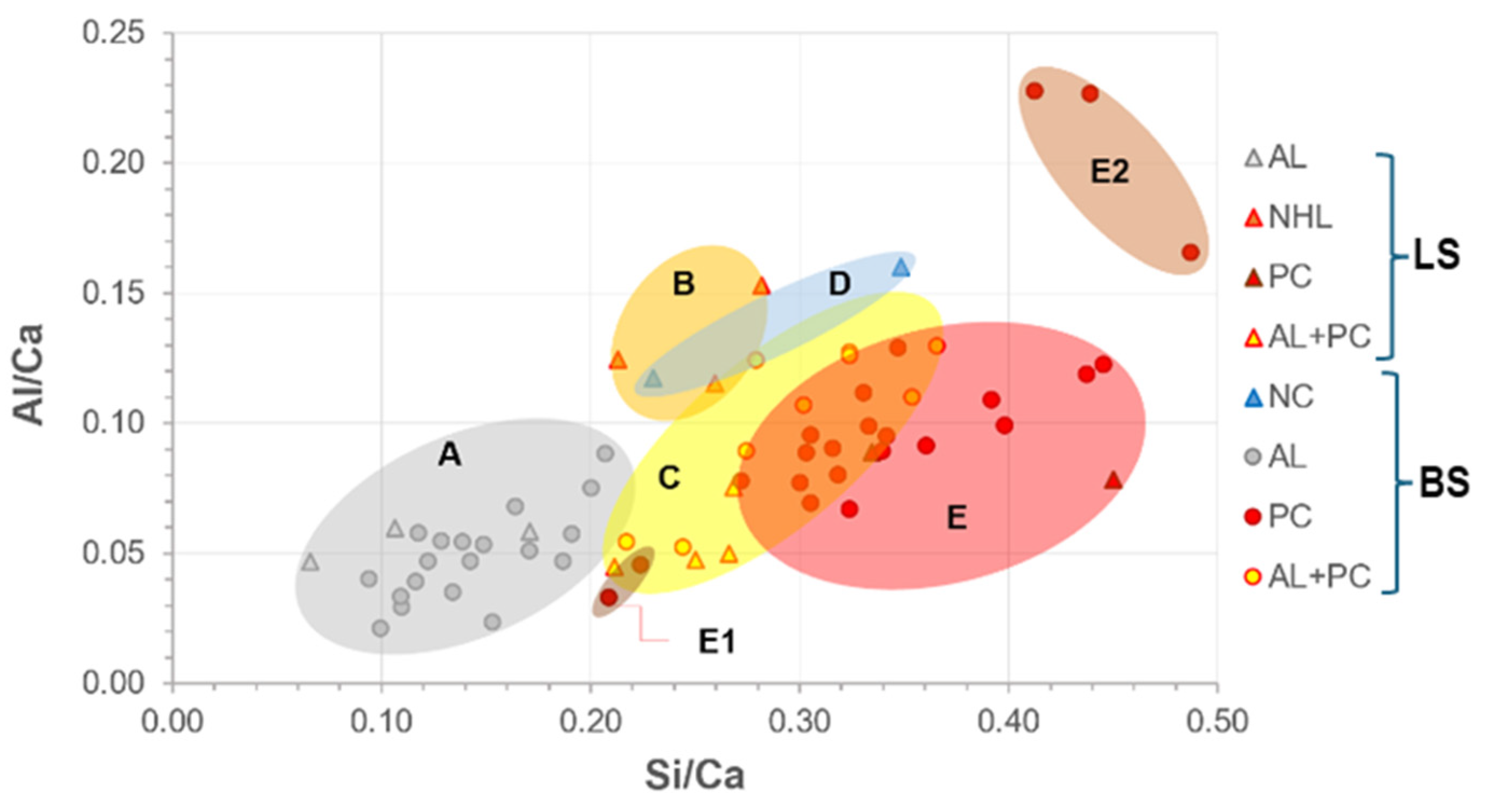
  • The interval ranges for the chemical compositions of the binders were obtained with precision through EDS analyses. The following interval of elemental ratios Al/Ca and Si/Ca were established for the types of binders identified in Table 5, ensuring the accuracy of the results.
Table 5. Ranges for chemical composition ratios (Al/Ca and Si/Ca) of binders.
Al/CaSi/Ca
Binder TypeMin.Max.Min.Max.
Air lime0.020.090.090.20
Natural hydraulic lime0.120.150.210.28
Natural cement0.120.160.230.35
Blended air lime and Portland cement (including ordinary, white, and Portland composite cement types)0.040.130.210.37
Portland cement (including ordinary and white types)0.030.230.210.45
Portland composite cements0.170.230.410.49
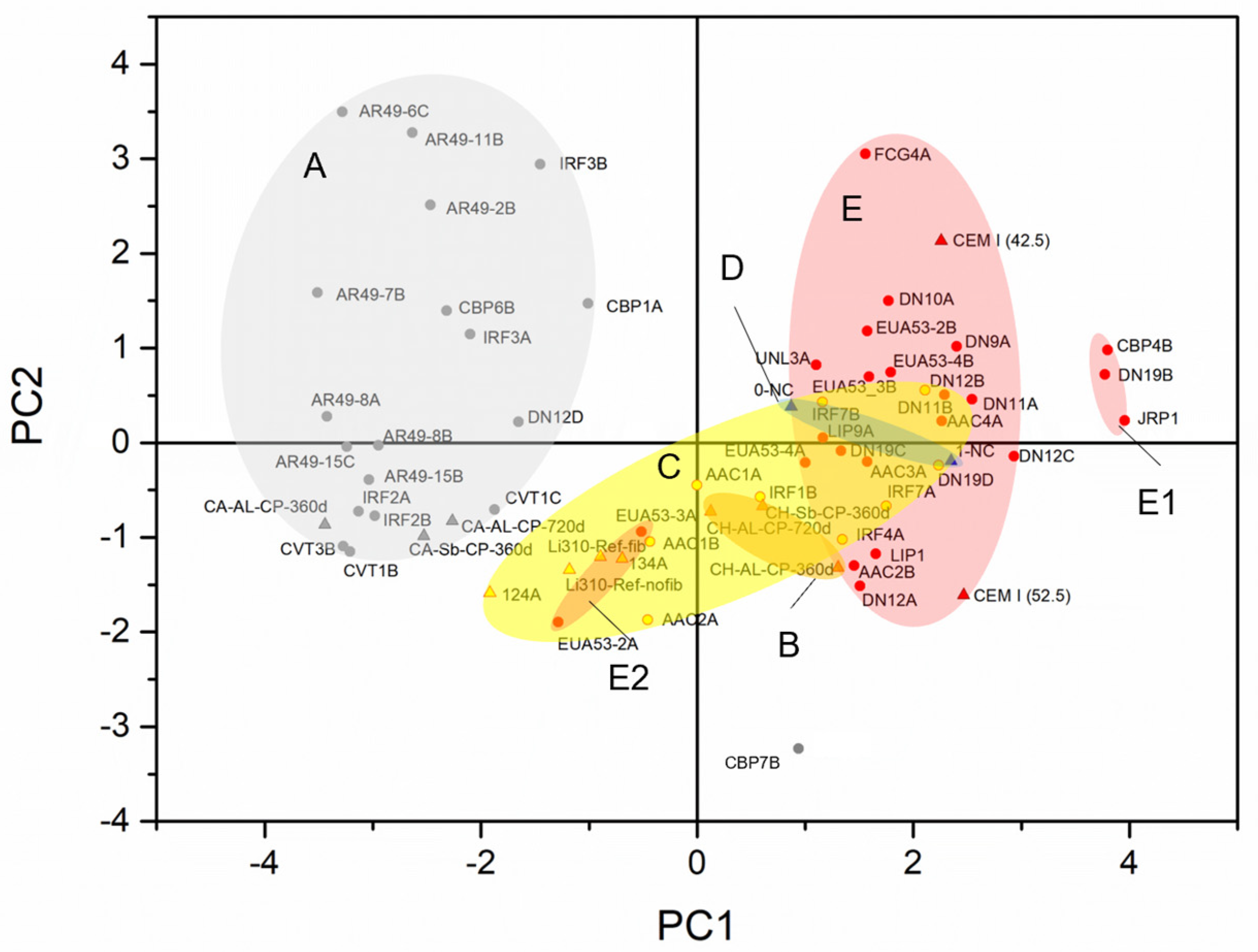
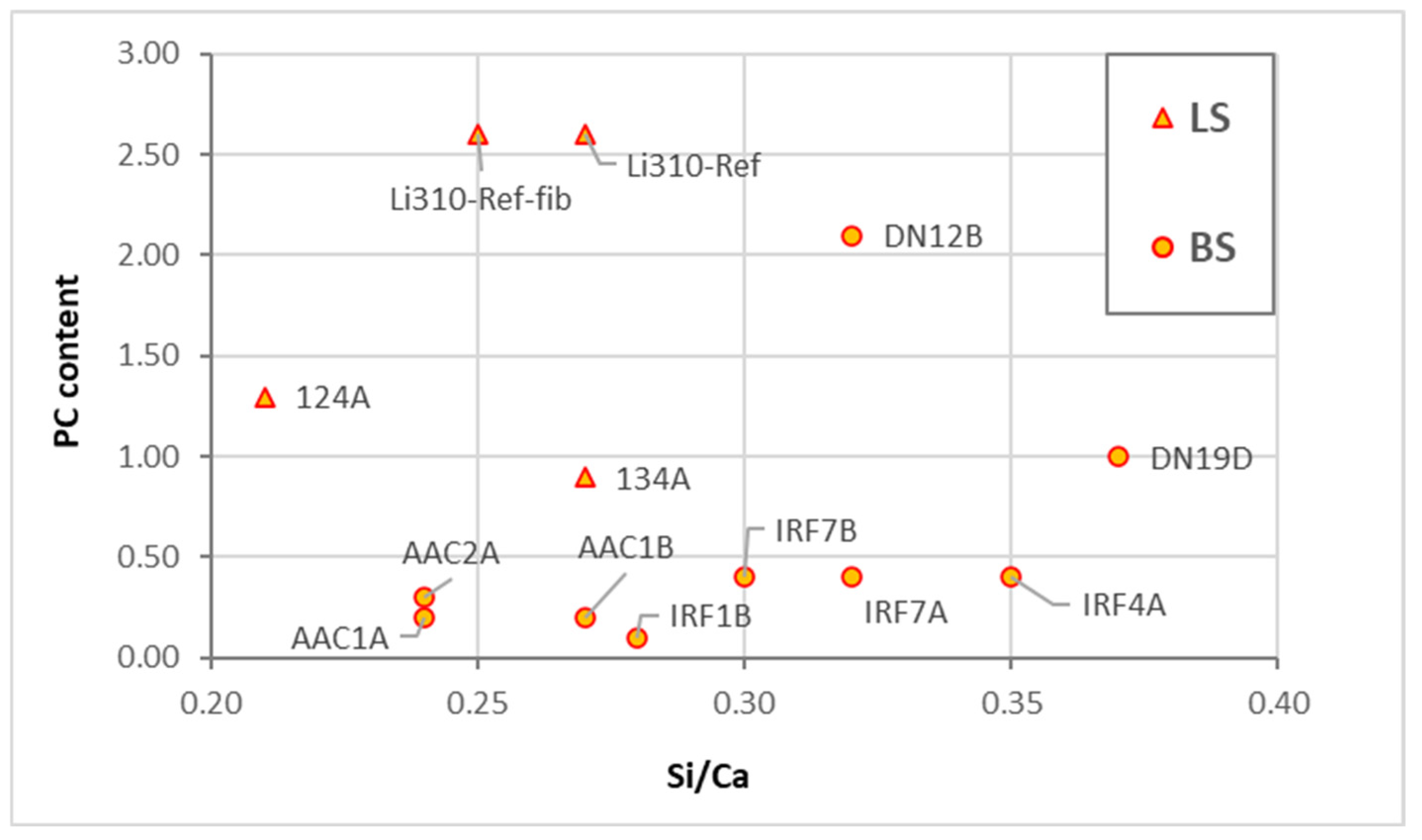
  • PCA analysis did not significantly refine the clusters because the samples have similar representations of the principal components. This suggests that PCA should not be applied to samples with elements that exhibit the same weight in their chemical composition.
  • When dealing with overlapping grouped chemical results, optical microscopy is a critical step in identifying the key compounds of the binder. When consistently applied by a skilled petrographer, this practice ensures the accuracy and reliability of the results.
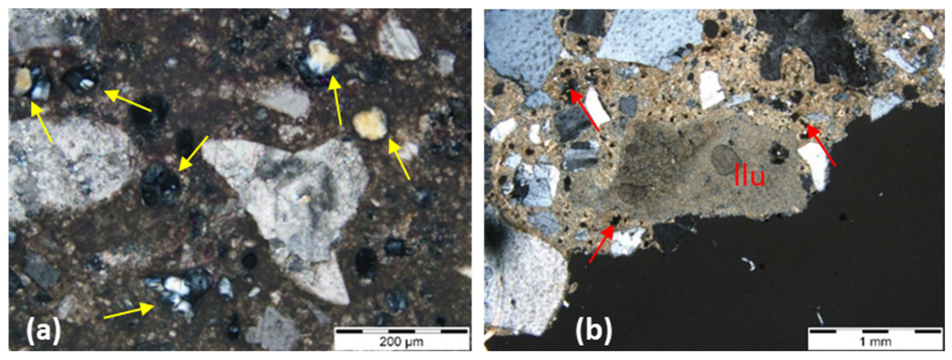
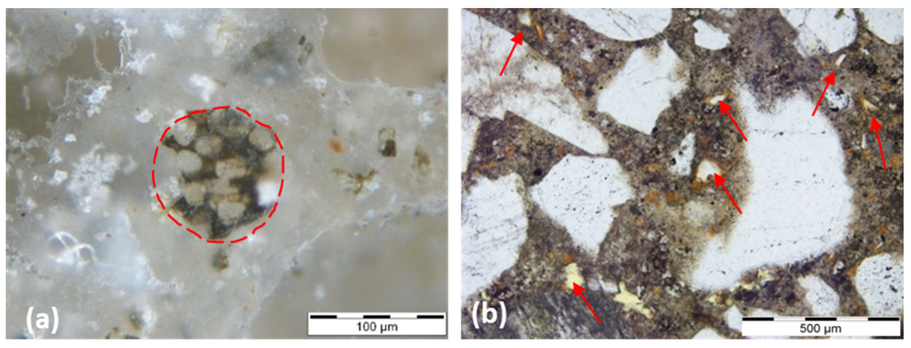
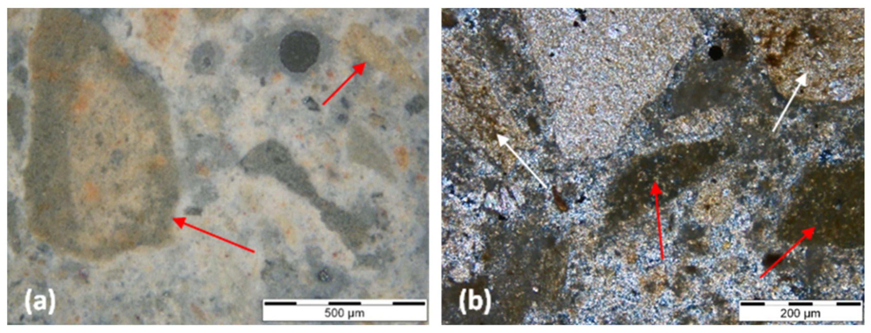
  • Of the key compounds mentioned above, some stand out in helping to distinguish between historical hydraulic binders, such as: natural cement binders (calcined marl fragments, under-burned, well-burned, and over-burned marl fragments, presence of unhydrated C2S crystals and the absence (or minimal presence) of alite); NHL binders (presence of small dark inclusions (non-hydrated relicts of C2S), hydration rims around individual hydraulic phases, presence of gehlenite); and portland cement binders (large size of the unhydrated C3S crystals in historic Portland cement and ubiquity of C3S in all types of Portland cement).
  • In blended mortars, the pastes’ homogeneity, or compositional variability, which may be attributable to the influence of the raw materials’ composition, varying according to their provenance, points to being influential in EDS analyses.
  • Although some of the samples analyzed were manufactured in the laboratory, namely the natural hydraulic lime, Portland cement, and air lime mixed with Portland cement test specimens, the chemical results can be extrapolated to these types of binders, historically applied in other periods, since the raw materials and calcination temperatures are similar to those obtained in the past, even though today there is greater quality control in the manufacturing processes.

Author Contributions

Conceptualization, L.A. and A.S.S.; methodology, L.A. and A.S.S.; software, L.A.; validation, A.S.S., R.V. and J.M.; investigation, L.A., A.S.S., R.V. and J.M.; writing—original draft preparation, L.A.; writing—review and editing, L.A., A.S.S., R.V. and J.M.; supervision, A.S.S., R.V. and J.M. All authors have read and agreed to the published version of the manuscript.

Funding

This research was funded by the Portuguese Foundation for Science and Technology—Fundação para a Ciência e a Tecnologia—FCT, grant SFRH/BD/112809/2015.

Data Availability Statement

Data is contained within the article.

Acknowledgments

The authors would like to acknowledge FCT through the PO-CI-01-0145-FEDER-031612 research project: ‘CEMRESTORE: Mortars for early 20th century buildings’ conservation: compatibility and sustainability’ and the collaborative researcher Judith Ramirez-Casas for making available thin sections of natural cement mortars from the Barcelona buildings. The authors would like to thank researcher Sílvia Pereira for her support in software computing. The authors also acknowledge the buildings’ owners for study authorizations and the National Laboratory for Civil Engineering for its support through the projects ‘DUR-HERITAGE—Durability and characterisation of historical interest construction materials’ and ‘PRESERVe—Preservation of renders from built heritage with cultural value: identification of risks and contribution of traditional knowledge and new materials for conservation and protection’.

Conflicts of Interest

The authors declare no conflicts of interest.

References

  1. Elsen, J.; Van Balen, K.; Mertens, G. Hydraulicity in historic mortars: A review. In Proceedings of the 2nd Historic Mortars Conference HMC2010 and RILEM TC 203-RHM Final Workshop, Prague, Czech Republic, 22–24 September 2010. [Google Scholar]
  2. Furlan, V.; Bissenger, P. Les mortiers anciens. Histoire et essai d’analyse scientifique. Rev. Suisse D’art D’archéol. 1975, 32, 2–14. [Google Scholar]
  3. Rispoli, C.; Montesano, G.; Verde, M.; Balassone, G.; Columbu, S.; De Bonis, A.; Di Benedetto, C.; D’Uva, F.; Esposito, R.; Graziano, S.F.; et al. The key to ancient Roman mortars hydraulicity: Ceramic fragments or volcanic materials? A lesson from the Phlegrean archaeological area (southern Italy). Constr. Build. Mater. 2024, 411, 134408. [Google Scholar] [CrossRef]
  4. Eramo, G.; Spalluto, L.; Laviano, R. Paving stones of the Via Traiana in Egnazia (Brindisi, 2nd A.D.): Provenance of stones [Il basolato della Via Traiana nel sito archeologico di Egnazia (Fasano, Br): Provenienza dei materiali lapidei]. Rend. Online Soc. Geol. Ital. 2008, 3, 357–358. [Google Scholar]
  5. Lezzerini, M.; Legnaioli, S.; Lorenzetti, G.; Palleschi, V.; Tamponi, M. Characterization of historical mortars from the bell tower of St. Nicholas church (Pisa, Italy). Constr. Build. Mater. 2014, 69, 203–212. [Google Scholar] [CrossRef]
  6. Miriello, D.; Bloise, A.; Crisci, G.M.; De Luca, R.; De Nigris, B.; Martellone, A.; Osanna, M.; Pace, R.; Pecci, A.; Ruggieri, N. New compositional data on ancient mortars and plasters from Pompeii (Campania—Southern Italy): Archaeometric results and considerations about their time evolution. Mater. Charact. 2018, 146, 189–203. [Google Scholar]
  7. Lezzerini, M.; Spampinato, M.; Sutter, A.; Montevecchi, N.; Aquino, A. Petrographic characteristics of the mortars from the Pisa’s Cathedral apse. In Proceedings of the IMEKO TC4 International Conference on Metrology for Archaeology and Cultural Heritage, MetroArchaeo, Calabria, Italy, 19–21 October 2022; pp. 459–463. [Google Scholar]
  8. Sitzia, F.; Beltrame, M.; Columbu, S.; Lisci, C.; Miguel, C.; Mirão, J. Ancient restoration and production technologies of Roman mortars from monuments placed in hydrogeological risk areas: A case study. Archaeol. Anthropol. Sci. 2020, 12, 147. [Google Scholar] [CrossRef]
  9. La Russa, M.F.; Ruffolo, S.A.; Ricca, M.; Rovella, N.; Comite, V.; De Buergo, M.A.; Crisci, G.M.; Barca, D. Archaeometric approach for the study of mortars from the underwater archaeological site of Baia (Naples) Italy: Preliminary results. Period. Miner. 2015, 84, 553–557. [Google Scholar] [CrossRef]
  10. Rispoli, C.; De Bonis, A.; Guarino, V.; Graziano, S.F.; di Benedetto, C.; Esposito, R.; Morra, V.; Cappelletti, P. The Ancient Pozzolanic Mortars of the Thermal Complex of Baia (Campi Flegrei, Italy). J. Cult. Herit. 2019, 40, 143–154. [Google Scholar] [CrossRef]
  11. Parker, J. A Certain Cement or Terras to Be Used in Aquatic and Other Buildings and Stucco Work. British Patent n. 2120, 27 July 1796. [Google Scholar]
  12. Kozłowski, R.; Hughes, D.; Weber, J. Roman cements: Key materials of the built heritage of the 19th Century. In Materials, Technologies and Practice in Historic Heritage Structures; Dan, M.B., Přikryl, R., Török, A., Eds.; Springer: Dordrecht, The Netherlands, 2010. [Google Scholar] [CrossRef]
  13. Hughes, D.; Swann, S.; Gardner, A. Roman cement. J. Arch. Conserv. 2007, 13, 21–36. [Google Scholar] [CrossRef]
  14. CEN EN 459-1; Building Lime—Part 1: Definitions, Specifications, and Conformity Criteria. European Committee for Standardization: Brussels, Belgium, 2015.
  15. Coutinho, A.S. Fabrico e Propriedades do Betão; Laboratório Nacional de Engenharia Civil (LNEC): Lisboa, Portugal, 1988; Volume 1. [Google Scholar]
  16. Weber, J.; Köberle, T.; Pintér, F. Methods of microscopy to identify and characterise hydraulic binders in historic mortars—A methodological approach. In Historic Mortars; Hughes, J., Válek, J., Groot, C., Eds.; Springer: Cham, Switzerland, 2019. [Google Scholar] [CrossRef]
  17. Callebaut, K.; Elsen, J.; Van Balen, K.; Viaene, W. Nineteenth century hydraulic restoration mortars in the Saint Michael’s Church (Leuven, Belgium): Natural hydraulic lime or cement? Cem. Concr. Res. 2001, 31, 397–403. [Google Scholar] [CrossRef]
  18. Gadermayr, N.; Pintér, F.; Weber, J. Identification of 19th century roman cements by the phase composition of clinker residues in historic mortars. In Proceedings of the 12th International Congress on the Deterioration and Conservation of Stone, New York, NY, USA, 22–25 October 2012. [Google Scholar]
  19. Taylor, H.F.W. Cement Chemistry; Academic Press: New York, NY, USA, 1990. [Google Scholar]
  20. Veiga, M.R.; Aguiar, J.; Santos Silva, A.; Carvalho, F. Conservação e Renovação de Revestimentos de Paredes de Edifícios Antigos; LNEC: Lisboa, Portugal, 2004; p. 126. [Google Scholar]
  21. Veiga, M.; Velosa, A.; Magalhães, A. Evaluation of mechanical compatibility of renders to apply on old walls based on a restrained shrinkage test. Mater. Struct. 2006, 40, 1115–1126. [Google Scholar]
  22. Almeida, L.; Santos Silva, A.; Veiga, R.; Mirão, J. Composition of renders and plasters of award-winning buildings in Lisbon (Portugal): A contribution to the knowledge of binders used in the 20th Century. Int. J. Arch. Herit. 2023, 1–31. [Google Scholar] [CrossRef]
  23. Mayo, C.M.; Ramírez-Casas, J.; Sanz, D.; Ezquerra, A.N.; Rosel, J.R. Methodology of identification of natural and historic Portland cements. Application and study in mortars of Madrid and Barcelona. In Proceedings of the 5th Historic Mortars Conference, Pamplona, Spain, 19–21 June 2019. [Google Scholar]
  24. Middendorf, B.; Hughes, J.J.; Callebaut, K.; Baronio, G.; Papayianni, I. Investigative methods for the characterisation of historic mortars—Part 2: Chemical characterisation. Mater. Struct. 2005, 38, 771–780. [Google Scholar] [CrossRef]
  25. Arliguie, G.; Hornain, H. Grandubé: Grandeurs Associées à la Durabilité des Bétons, 1st ed.; Presses Ecole Nationale Ponts Chaussees: Paris, France, 2007; p. 438. [Google Scholar]
  26. Lindqvist, J.E.; Sandström, M. Recommendations of RILEM TC 167-COM: Characterization of old mortars. Quantitative analysis of historical mortars using optical microscopy. Mater. Struct. 2000, 167, 612–617. [Google Scholar] [CrossRef]
  27. Walsh, J.J. Petrography: Distinguishing Natural Cement from Other Binders in Historical Masonry Construction Using Forensic Microscopy Techniques. J. ASTM Intern. 2007, 4, 1. [Google Scholar]
  28. Pavia, S.; Caro, S. Petrographic microscope investigation of mortar and ceramic technologies for the conservation of the built heritage. In Proceedings of the SPIE O3A: Optics for Arts, Architecture, and Archaeology, Munich, Germany, 16 July 2007; Volume 6618. [Google Scholar]
  29. Mertens, G.; Madau, P.; Durinck, D.; Blanpain, B.; Elsen, J. Quantitative mineralogical analysis of hydraulic limes by X-ray diffraction. Cem. Concr. Res. 2007, 37, 1524–1530. [Google Scholar] [CrossRef]
  30. Santos, A.R.; Veiga, M.R.; Santos Silva, A.; Brito, J.; Álvarez, J.I. Evolution of the microstructure of lime based mortars and influence on the mechanical behaviour: The role of the aggregates. Constr. Build. Mater. 2018, 187, 907–922. [Google Scholar] [CrossRef]
  31. Santos, A.R.; Veiga, M.R.; Santos Silva, A.; Brito, J. Impact of aggregates on fresh mortars’ properties. In Proceedings of the 5th Historic Mortars Conference, Pamplona, Spain, 19–21 June 2019. [Google Scholar]
  32. Pederneiras, C.M. Improving Cracking Performance of Mortars with Selected Recycled Fibres for Non-Structural Uses. Ph.D. Thesis, Civil Engineering, Instituto Superior Técnico, University of Lisbon, Lisbon, Portugal, 2021. [Google Scholar]
  33. Famya, C.; Brough, A.R.; Taylor, H.F.W. The C-S-H gel of Portland cement mortars: Part I. The interpretation of energy-dispersive X-ray microanalyses from scanning electron microscopy, with some observations on C-S-H, AFm and Aft phase compositions. Cem. Concr. Res. 2003, 3, 1389–1398. [Google Scholar]
  34. Balksten, K.; Nitz, B.; Hughes, J.J.; Lindqvist, J.E. Petrography of historic mortar materials: Polarising light microscopy as a method for characterising lime-based mortars. In Proceedings of the 5th Historic Mortars Conference, Universidad de Navarra, Pamplona, Spain, 19–21 June 2019. [Google Scholar]
  35. Elsen, J.; Mertens, G.; Snellings, R. Portland cement and other calcareous hydraulic binders: History, production and mineralogy. Europ. Mineral. Uni. Notes Miner. 2011, 9, 441–479. [Google Scholar] [CrossRef]
  36. Vicat, L.J. Recherches Expérimentales sur les Chaux de Construction, les Bétons et les Mortiers Ordinaires; Goujon: Paris, France, 1818. [Google Scholar]
  37. Eckel, E. Cements, Limes and Plasters. Their Materials, Manufacture and Properties; Routledge, Taylor & Francis Group: New York, NY, USA, 2015. [Google Scholar]
  38. Mertens, G.; Elsen, J.; Laduron, D.; Brulet, R. Mineralogy of the calcium-silicate phases present in ancient mortars from Tournai. Archeometrie 2006, 30, 61–65. [Google Scholar]
  39. Mertens, G.; Lindqvist, J.E.; Sommain, D.; Elsen, J. Calcareous Hydraulic Binders from a Historical Perspective. In Proceedings of the 1st Historical Mortars Conference, Characterization, Diagnosis, Conservation, Repair and Compatibility, Lisbon, Portugal, 24–28 September 2008; pp. 1–15. [Google Scholar]
  40. Pecchioni, E.; Fratini, F.; Cantisani, E. Atlas of the Ancient Mortars in Thin Section Under Optical Microscope, 2nd ed.; Nardini: Florence, Italy, 2020; p. 78. [Google Scholar]
  41. Bugini, R.; Toniolo, L. La presenza di grumi bianchi nelle malte antiche: Ipotesi sull’origine. Arkos 1990, 12, 4–8. [Google Scholar]
  42. Cantisani, E.; Fratini, F.; Pecchioni, E. Optical and Electronic Microscope for Minero-Petrographic and Microchemical Studies of Lime Binders of Ancient Mortars. Minerals 2022, 12, 41. [Google Scholar] [CrossRef]
  43. Hughes, J.; Cuthbert, S. The petrography and microstructure of medieval lime mortars from the west of Scotland: Implications for the formulation of repair and replacement mortars. Mater. Struct. 2000, 33, 594–600. [Google Scholar]
  44. Pavia, S.; Fitzgerald, B.; Howard, R. Evaluation of properties of magnesian lime mortar. In Structural Studies, Repair, and Maintenance of Heritage Architecture IX; Brebbia, C.A., Torpiano, A., Eds.; Transactions on the Built Environment; WIT Press: Southampton, UK, 2005; Volume 83, pp. 375–384. [Google Scholar]
  45. Leslie, A.B.; Hughes, J.J. Binder microstructure in lime mortars: Implications for the interpretation of analysis results. Quart. J. Eng. Geol. 2002, 35, 257–263. [Google Scholar]
  46. Leslie, A.B.; Gibbons, P. Mortar analysis and repair specification in the conservation of Scottish historic buildings. In Proceedings of the International RILEM Workshop on Historic Mortars: Characteristics and Tests; Bartos, P., Groot, C., Hughes, J.J., Eds.; RILEM: Paisley, UK, 2000; pp. 273–280. [Google Scholar]
  47. Furlan, V.; Pancella, R. Examen microscopique en lumière rèfléchie de ciments, bétons et mortiers. Chantiers 1982, 13, 25–30. [Google Scholar]
  48. Gödicke-Dettmering, T.; Strübel, G. Mineralogische und technologische Eigenschaften von hydraulischen Kalken als Bindemittel für Restaurierungsmörtel in der Denkmalpflege. Giessener Geol. Schr. 1996, 56, 131–154. [Google Scholar]
  49. Pecchioni, E.; Fratini, F.; Cantisani, C. Le Malte Antiche e Moderne tra Tradizione e Innovazione, 2nd ed.; Pàtron: Bologna, Italy, 2018; p. 231. [Google Scholar]
  50. Moropoulu, A.; Cakmak, A.S.; Biscontin, G.; Bakolas, A.; Zendri, E. Advanced Byzantine cement based composites resisting earthquake stress: The crushed brick/lime mortars of Justinian’s Hagia Sophia. Constr. Build. Mater. 2002, 16, 543–552. [Google Scholar]
  51. Ingham, J. Geomaterials under the Microscope: A Colour Guide; John Wiley & Sons: Hoboken, NJ, USA, 2010; p. 192. [Google Scholar]
  52. Mayo, C.; Sanz, D.; Pineda, J.I. Metodología simplificada de identificación mediante MOP de las cales hidráulicas y los cementos naturales. In Proceedings of the VI Jornadas FICAL—Forum Iberico de la Cal, Pamplona, Spain, 28–30 May 2018. [Google Scholar]
  53. Jepsen, B.B.; Christensen, P. Petrographic examination of hardened concrete. Bull. Intern. Assoc. Engin. Geol. 1989, 39, 99–103. [Google Scholar]
  54. Poole, A.; Sims, I. Concrete Petrography. A Handbook of Investigative Techniques, 2nd ed.; CRC Press: Boca Raton, FL, USA, 2020. [Google Scholar]
  55. Pavía, S. A Petrographic study of the technology of hydraulic mortars at masonry bridges, harbours and mill ponds. In Proceedings of the Concrete Research and Bridge Infrastructure Symposium, Galway, Ireland, 4–5 December 2008; pp. 253–264. [Google Scholar]
Figure 1. Si/Ca vs. Al/Ca plot of laboratory test specimens (LS) and building samples (BS) with clustering. Group A: air lime mortars (AL). Group B: NHL mortars (B). Group C: blended air lime Portland cement mortars (AL+PC). Group D: natural cement mortars (NC). Group E: Portland cement mortars (PC). Sub-group E1: Portland cement stone imitating mortars with limestone filler. Sub-group E2: Portland cement mortars with mineral additions or with pozzolanic additives. PC includes all types of Portland cement.
Minerals 14 00844 g001
Figure 2. Score plot of the PCA of the analyzed samples, including the laboratory test specimens. Legend: Group A: air lime mortars (AL). Group B: NHL mortars (B). Group C: blended air lime with Portland cement mortars (AL+PC). Group D: natural cement mortars (NC). Group E: Portland cement mortars (PC). Sub-group E1: Portland cement stone imitating mortars with limestone filler. Sub-group E2: Portland cement mortars with mineral additions or with pozzolanic potential. PC includes all types of Portland cement.
Minerals 14 00844 g002
Figure 3. Loadings plot of the PCA of the experimental and the laboratory test specimens.
Minerals 14 00844 g003
Figure 4. XRD patterns of the samples CVT1C, CVT3B, AR49-7B, and AR49-11B. Notation: OF—overall fraction; BRF—binder-rich fraction; M—muscovite; G—gypsum; Q—quartz; Fna—albite; Fk—microcline; C—calcite; Ha—halite; Eu—eugsterite; Th—thenardite; K—kaolinite.
Minerals 14 00844 g004
Figure 5. Backscattered scanning electron images of the binder of the sample CBP7B. (a) Needle-shape gypsum crystals forming a loose-like binder network; (b) X-ray map of elements K (red), Ca (green), and S (blue); X-ray maps of elements Ca (c) and S (d).
Minerals 14 00844 g005
Figure 6. Si/Ca to Portland cement content (from b:a ratio) in the lime-mixed Portland cement mortars. Legend: LS—laboratory mortar specimens; BS—building mortar samples.
Minerals 14 00844 g006
Figure 7. AR49-6C (a) and IRF2B (b) thin section micrographs in transmitted cross-polarized light, showing lime lumps (llu).
Minerals 14 00844 g007
Figure 8. Thin-section micrograph of EUA53-4A in transmitted cross-polarized light (a), and thin section micrograph of IRF4A in transmitted cross-polarized light (b). Legend: unhydrated white Portland cement clinker grains (yellow arrows) showing no C4AF phase in the residual cement grains; lime lump (llu) and Portland cement clinker grains (red arrows) coexisting in the same sample, indicating air lime with mixed ordinary Portland cement as binders.
Minerals 14 00844 g008
Figure 9. Polished section micrograph of Li310-Ref test specimen in incident light, dark field (a), and thin section micrograph of JRP2A sample in transmitted plane polarized light (b). Legend: unhydrated Portland cement clinker grain (red doted circle) containing C3S (elongated), C2S (rounded crystals) and a brownish phase corresponding to C4AF; GBFS grains in a Portland cement matrix, showing typical orange to red hydration rims (red arrows).
Minerals 14 00844 g009
Figure 10. 0-NC thin section micrographs. Legend: (a)—fragments of calcined marl from the natural cement sample in incident light, dark field. These fragments are characterized by a hydrated outer ring (red arrows); (b)—detail of marls with non-hydrated belite inside lumps (red arrows); residual, under-burned relicts exhibiting low reactivity (white arrows) and the original rock texture observed in transmitted cross-polarized light.
Minerals 14 00844 g010
Table 1. Mortars from Lisbon (Portugal) and Barcelona (Spain) buildings.
Sample IDConstruction PeriodCase Study/BuildingType of BuildingBinder TypeBinder to Aggregate Ratio by Weight (b:a)
CVT1B1902–1903CVT (1903)/
Ventura Terra building (Lisbon)
ResidencialAL1:5.4
CVT1CAL1:7.8
CVT3BAL1:4.3
AR49-2B1920–1923AR49 (1923)/
Luiz Rau building (Lisbon)
ResidentialAL(c)
AR49-6CAL1:5.8
AR49-7BAL1:3
AR49-8AAL1:2.9
AR49-8BAL1:11.2
AR49-11BAL1:6.7
AR49-15BAL1:7.1
AR49-15CAL1:7.9
IRF1B1934–1938IRF (1938)/Nossa Senhora de Fátima church (Lisbon)ChurchAL+OPC1:0.1:7
IRF2AAL1:4.3
IRF2BAL1:9.9
IRF3AAL1:4.2
IRF3BAL1:8
IRF4AAL+OPC1:0.4:5.4
IRF7AAL+OPC1:0.4:3.8
IRF7BAL+OPC1:0.4:5.3
CBP1A1938–1939CBP (1939)/Bernardo da Maia house (Lisbon)ResidentialAL1:8.4
CBP4B (d)OPC1:20.3
CBP6BAL1:8.7
CBP7BAL1:11.2
DN9A1936–1940DN (1940)/Diário de Notícias building (Lisbon)Office and serviceOPC1:6.1
DN10AOPC1:7
DN11AOPC1:7.4
DN11BOPC1:4.2
DN12AOPC1:12.9
DN12BAL+OPC1:2.1:15.1
DN12COPC1:4.2
DN12DAL1:4.3
DN19BPCC1:25.2 (a)
DN19COPC1:8.9
DN19DAL+PCC1:1:6 (a)
AAC1A1942–1944AAC (1944)/Cristino da Silva building (Lisbon) ResidentialAL+OPC1:0.2:6.1
AAC1BAL+OPC1:0.2:7
AAC2A (c)AL+WPC1:0.3:1.0
AAC2BOPC1:24.5
AAC3A (c)OPC1:3.0
AAC4A (c)OPC1:1.9
LIP1A1955–1957LIP (1954)/Laboratories of Pasteur Institute of Lisbon (Lisbon)Laboratory and servicesOPC1:7.6
LIP9AOPC1:6.6
EUA53-2A (c)1966–1969EUA53 (1970)/America building (Lisbon)Residential and commercialWPC (e)1:3.7
EUA53-2BOPC1:6.7
EUA53-3A (c)WPC (e)1:19.1
EUA53-3BOPC1:4.9
EUA53-4A (c)WPC1:11.1
EUA53-4BOPC1:11.5
FCG4A1963–1969FCG (1975)/Calouste Gulbenkian Foundation Headquarters and Museum (Lisbon)Office and cultural facilities OPC1:10.2
JRP2A1984–1987JRP (1987)/Jacob Rodrigues Pereira Institute (Lisbon)Educational/academicPCC1:4.9 (a)
UNL3A2000–2002UNL (2002)/New University of Lisbon Rectory (Lisbon)Educational/academicOPC1:10.2
0-NC1887Hivernacle (Barcelona)GreenhouseNC(b)
1-NC1900Villarroel (Barcelona)ResidentialNC(b)
Legend: AL—air lime; OPC—ordinary Portland cement; WPC—white Portland cement; PCC—Portland composite cement; NC—natural cement; (a)—overestimated aggregate content, due to the presence of mineral additions (GGBS—samples DN19D and JRP2; FA—sample DN19D); (b)—not assessed; (c)—stone-imitating mortars; (d)—mortar with ceramic aggregates; (e)—stone imitating mortar with limestone filler.
Table 2. Composition of laboratory formulated mortar specimens.
Specimens ID Mortar Formulation Binder Type b:a (a)
CA-Sb-CP-360d CL90-S air lime mortar with siliceous sand, 360 days laboratory curing AL 1:11
CA-AL-CP-360d CL90-S air lime mortar with washed siliceous sand, 360 days laboratory curing AL 1:11
CH-AL-CP-360d NHL 3.5 (1) mortar with washed siliceous sand, 360 days laboratory curing NHL 1:5.6
CH-Sb-CP-360d NHL 3.5 (1) mortar with siliceous sand, 360 days laboratory curing NHL 1:5.6
CEM I (42.5) Portland cement mortar (CEM I 42.5) with siliceous sand, 180 days laboratory curing OPC 1:3
CEM I (52.5) Portland cement type mortar (CEM I 52.5) with siliceous sand, 180 days laboratory curing OPC 1:3
Li310-Ref-fib Blended mortar with air lime and Portland cement (CEM I 42.5) with siliceous sand and organic fibers, 360 days laboratory curingAL+OPC 1:2.6:26.3
Li310-Ref Blended mortar with air lime and Portland cement (CEM I 42.5) with siliceous sand, 360 days laboratory curing AL+OPC 1:2.6:26.3
CA-AL-CP-720d CL90-S air lime mortar with washed siliceous sand, 720 days laboratory curing AL 1:11
CH-AL-CP-720d NHL 3.5 (1) mortar with washed siliceous sand, 720 days laboratory curing NHL 1:5.6
124A Blended mortars with air lime and white Portland cement (CEM I 42.5) with siliceous sand, 4 years laboratory curing AL+WPC 1:1.3:19.7
134A AL+WPC 1:0.9:17.5
Legend: AL—air lime; OPC—ordinary Portland cement; WPC—white Portland cement; NHL—natural hydraulic lime; AL+OPC (or WPC)—blended air lime and ordinary Portland cement or white Portland cement; (a)—binder to aggregate ratio; (1) The commercial SECIL NHL 3.5 is rated according to CEN EN 459-1:2015 [14].
Table 3. Al/Ca and Si/Ca atomic ratios obtained by EDS of the mortars from the buildings analyzed and of laboratory formulated test specimens.
Sample ID Case StudyBinder Type Al/Ca Si/Ca
CVT1B Lisbon
buildings
CVT (1903) AL 0.03 0.11
CVT1C AL 0.06 0.19
CVT3B AL 0.02 0.15
AR49-2B AR49 (1923) AL 0.05 0.13
AR49-6C AL 0.05 0.12
AR49-7B AL 0.02 0.10
AR49-8A AL 0.03 0.11
AR49-8B AL 0.05 0.19
AR49-11B AL 0.07 0.16
AR49-15B AL 0.05 0.14
AR49-15C AL 0.05 0.17
IRF1B IRF (1938) AL+OPC 0.12 0.28
IRF2A AL 0.04 0.09
IRF2B AL 0.04 0.12
IRF3A AL 0.06 0.12
IRF3B AL 0.05 0.14
IRF4A AL+OPC 0.11 0.35
IRF7A AL+OPC 0.13 0.32
IRF7B AL+OPC 0.11 0.30
CBP1A CBP (1939) AL 0.07 0.20
CBP4B OPC0.23 0.44
CBP6B AL 0.03 0.13
CBP7B AL 0.09 0.21
DN9A DN (1940) OPC 0.11 0.39
DN10A OPC 0.09 0.34
DN11A OPC 0.10 0.40
DN11B OPC 0.10 0.33
DN12A OPC 0.12 0.44
DN12B AL+OPC 0.13 0.32
DN12C OPC 0.12 0.45
DN12D AL 0.05 0.15
DN19B PCC 0.23 0.41
DN19C OPC 0.07 0.31
DN19D AL+PCC 0.13 0.37
AAC1A AAC (1944) AL+OPC 0.05 0.24
AAC1B AL+OPC 0.09 0.27
AAC2A AL+WPC 0.05 0.22
AAC2B OPC 0.09 0.36
AAC3A OPC 0.10 0.31
AAC4A OPC 0.09 0.34
LIP1A LIP (1954) OPC 0.13 0.35
LIP9A OPC 0.07 0.32
EUA53-2A EUA53 (1970) WPC0.05 0.22
EUA53-2B OPC 0.09 0.30
EUA53-3A WPC0.03 0.21
EUA53-3B OPC 0.08 0.32
EUA53-4A WPC 0.08 0.30
EUA53-4B OPC 0.09 0.32
FCG4A FCG (1975) OPC 0.11 0.33
JRP2A JRP (1987) PCC0.17 0.49
UNL3A UNL (2002) OPC 0.08 0.27
CA-Sb-CP-360d Laboratory formulated test specimens AL 0.06 0.11
CA-AL-CP-360d AL 0.05 0.07
CH-AL-CP-360d NHL 0.15 0.26
CH-Sb-CP-360d NHL 0.12 0.21
CEM I (42.5) OPC 0.09 0.33
CEM I (52.5) OPC 0.08 0.45
Li310-Ref-fib AL+OPC 0.05 0.25
Li310-Ref AL+OPC 0.05 0.27
CA-AL-CP-720d AL 0.06 0.17
CH-AL-CP-720d NHL 0.12 0.28
124A AL+WPC 0.04 0.21
134A AL+WPC 0.08 0.27
0-NC Barcelona buildings NC 0.12 0.23
1-NC NC 0.16 0.35
Legend: AL—air lime; OPC—ordinary Portland cement; WPC—white Portland cement; PCC—Portland composite cement; AL+OPC (or WPC, or PCC)—blended air lime and Portland cement (for each type); NHL—natural hydraulic lime; NC—natural cement.
Table 4. Main characteristics for identifying binders by optical microscopy according to several authors.
Authors [by Reference]
NHL and other hydraulic lime mortars/binders[17][27][47][48][49,50][40,49,51][51]
Large C2S and C3S phases in a small amount of a brown matrix consisting of C3A and C4AF.Small clusters of C2S may be detected in trace quantities in hydraulic limes.Dominant C2S grains can present striations in different directionsPresence of “hot spots” as part of the hydraulic phases that result from local higher temperatures in the lime kiln.If reaction rims did not develop, hydraulic phases dispersed in the binder can nevertheless still be observed both as veins and as pore filling.Presence of small dark inclusions (non-hydrated relicts of C2S) that can be easily recognised.C3S can be formed due to an overheating of the raw materials during the production of NHL
C3S can also be present in smaller quantities.Hydration rims can be observed around individual hydraulic phases as a colourless rim.The presence of gehlenite is a valuable indicator of the distinction between cement and natural hydraulic lime. C2S: dark brown crystals medium-high relief, shaded contours, and sub idiomorphic habit.
Natural cement[16][23][27][13][52]
The NC residual nodules exhibit strong zoning which is best visible in transmitted light with parallel polars.Presence of lumps of calcined marls in the natural cement (due to the calcination and to the deficient milling technology).Under polarised light, the matrix of natural cements often appears spotted with dark isotropic areas broken by bright but dense carbonated regions.High proportion of non-reactive ‘nodules’ or relicts (under-burned, well burned, and over-burned). Under-burned, well burned, and over-burned marl fragments.
NC mortars can be identified equally well at low magnifications as their binders contain residual compounds that are larger than the clinker of historic Portland cement.Presence of unhydrated C2S crystals.The dispersed quartz grains and other sand-sized silicate minerals also aid in distinguishing natural cements. These tend to retain most of their original texture when burned at calcining temperatures.The largest ‘nodules’ are of millimetre size.NHL does not show calcined marl fragments and have a more homogeneous structure.
Absence of unhydrated C3S crystals. Contain greater percentage of relicts than either the hydraulic limes or the Portland cements.Lime nodules can be observed in the NHL samples, while the natural cements lack these nodules.
OPC[23][27][53,54,55]
Large size of the unhydrated C3S crystals
in historic Portland cements. The calcination process in vertical kilns was longer than in a modern horizontal kiln and it allowed the C2S and C3S crystals to acquire a larger size than in modern Portland cement.
Portland cement pastes are homogeneously isotropic or dark-colored where cementitious gels have formed, broken only by thin dispersed grains of calcium hydroxide that appear bright-colored.The unhydrated cement grains are identified by the optical properties of the cement minerals, primarily C3S and C2S.
WPC[27]
The C2S phases are not surrounded by a brown-colored crystallographically indistinct ferrite phase (absence of brownish C4AF in the residual cement grains).
PCC[53,54]
Unhydrated fly ash particles; GBFS—glassy slag particles with reddish hydration rims.
Disclaimer/Publisher’s Note: The statements, opinions and data contained in all publications are solely those of the individual author(s) and contributor(s) and not of MDPI and/or the editor(s). MDPI and/or the editor(s) disclaim responsibility for any injury to people or property resulting from any ideas, methods, instructions or products referred to in the content.

