Article

Development of a Simulator for Random and Non-Random Breakage of Particles and Liberation of Grains Based on Voronoi Tessellation

by
Zeinab Sadat Mirzaei
and
Mohammad Reza Khalesi
*
Department of Mining Engineering, Tarbiat Modares University, Tehran 1411713116, Iran
*
Author to whom correspondence should be addressed.
Minerals 2019, 9(6), 341; https://doi.org/10.3390/min9060341
Submission received: 12 April 2019 / Revised: 27 May 2019 / Accepted: 30 May 2019 / Published: 3 June 2019
(This article belongs to the Special Issue Mineral Liberation)

Abstract

:
In mineral processing, liberation of valuable mineral from gangue minerals is the most important stage before the concentration process. Comminution, which leads to liberation, includes two types of random and non-random breakages. The contribution of random and non-random breakage is very important in modelling the liberation phenomenon. In this paper, a simulator based on 2D Voronoi tessellation is introduced which can simulate random, preferential and detachment breakages of binary ores (valuable and gangue mineral). This simulator has been validated by image analysis of fragmented artificial ores which were made in different grades and comminuted in different energy levels by a drop weight device. The data obtained from images of comminuted particles were processed using the codes prepared in MATLAB®. Results showed that for the samples used in this study, the proportion of the intergranular breakage changes as the grade of the ore changes, with an agreement between simulations and experiments, independently from the energy level of comminution.

1. Introduction

The grade and recovery of concentrates in different mineral processing systems depends on the extent of liberation of valuable minerals and their separation efficiency from gangue minerals [1]. Liberation of valuable mineral is the most important stage before the concentration process [2,3]. The changes in the distribution of the mineral grade of particles due to breakage, is called liberation [4]. Many researches have focused on reducing the operational costs of grinding, as if the most important role of grinding, i.e., liberation, is sometimes forgotten [5]. Liberation of valuable minerals from the gangues occurs due to two types of breakage. If the interfacial area is strong enough and the resistance to breakage is the same in different phases, random breakage occurs. If the interfacial area is weak, intergranular (non-random) breakage occurs [6]. Other forms of non-random breakage include preferential breakage in which crack propagation occurs more frequently in one of the mineral phases [7]. To model the liberation of minerals, many researchers have assumed the breakage to be random in order to reduce the complexity of the problem [8,9,10], since in this case the selection function will be independent of particle size and the ore texture [11]. Briefly, random breakage can be defined as the independence of the failure process from both the mineralogical and mechanical characteristics during the grinding process [12]. The assumption of random breakage leads to the conclusion that by changing the size of the particles during the grinding process, the average grade does not change in different size classes, and the grade is equal in all classes to the feed grade [13]. Such unrealistic assumptions have limited the application of these models in practical cases [14], as the existence of non-random breakage has been confirmed in many ores [15,16].
Apart from the complexity of the development of liberation models for non-random breakages, the quantification of contribution of random and non-random breakages in a real comminuted ore has been a challenge and many researchers have tried to provide a methodology for estimating such a contribution. For example, Gaudin (1939) explained that liberation due to detachment or selective breakage in the grain boundary can be determined by examining the mineral distribution in different size classes, since a bimodal distribution will be produced due to detachment [8]. However, as this phenomenon may be produced by other mechanisms too, it does not represent detachment breakage independently [17]. Laslett et al. (1990) observed that in comminution of chalcopyrite ore, the mineral grade and interfacial area in different size classes are not constant and therefore the dominance of random breakage was not approved [18]. Choi et al. (1988) estimated the breakage rate of a real multi-phase ore from the breakage rates of each component. They suggest that the difference between these two measurements is due to preferential breakage at the grain boundaries [19]. The measurement of the phase-specific surface area between special phases before and after the breakage is the main method for quantifying the proportion of intergranular breakage [20,21,22]. King (1990) referred to the conservation of the interfacial surface area in random breakage [23]. Little et al. (2016) proved the existence of intergranular breakage in an ore according to the conservation of grain shape and by comparing the degree of liberation and phase-specific interfacial area [24]. Recently, Leiβner et al. (2016) introduced a quantitative method to determine the proportion of intergranular and transgranular breakage based on 2D analysis of surface exposure of minerals. The theory of this method is that the Surface Area (SA) of a mineral is composed of the Interfacial Area (IA) between the different phases of the minerals and the area of the Free Surface (FS) of the mineral [25].
SA = IA + FS
The common area of a mineral attached to another is determined by the length of the boundary line of these two phases in a 2D analysis. According to Figure 1a, the Interfacial Area (IA) for phase 1 is equal to l1 + l2 and its Free Surface (FS) is equal to l3. Each of these amounts transform to a phase-specific parameter by dividing by phase area [25].
P S S A = P S I A + P S F S = l 1 + l 2 A 1 + l 3 A 1
where PSSA is the Phase-Specific Surface Area, PSIA is the Phase-Specific Interfacial Area, PSFS is the Phase-Specific Free Surface, and A1 is the Area of Phase 1. After the breakage, phase-specific variables for the product particles should be calculated. Suppose that a fracture line which leads to pure transgranular breakage divides phase 1 into two bodies attached to other phases (as seen in Figure 1b with areas of A12 and A13, where A12 + A13 = A1). It can be seen that:
B F ¯ + F D ¯ = l 6 + l 7 = l 3
D E ¯ + E C ¯ = l 4 + l 5 = l 1
P S S A = S A 12 + S A 13 A 12 + A 13 = l 8 + l 8 + l 7 + l 6 + l 4 + l 5 + l 2 A 1 = l 2 + l 1 + l 3 + 2 l 8 A 1
P S I A = l 4 + l 5 + l 2 A 12 + A 13 = l 1 + l 2 A 1
P S F S = l 8 + l 8 + l 7 + l 6 A 12 + A 13 = l 3 + 2 l 8 A 1
where SA12 and SA13 are the Surface Areas (not Phase-Specific) of new generated particles with areas of A12 and A13. Therefore, the change in phase-specific variables after the breakage is calculated as:
| Δ P S F S | = | l 3 A 1 l 3 + 2 l 8 A 1 | = | 2 l 8 A 1 | = 2 l 8 A 1
| Δ P S I A | = | l 1 + l 2 A 1 l 1 + l 2 A 1 | = 0
| Δ P S S A | = | l 1 + l 2 + l 3 A 1 l 1 + l 2 + l 3 + 2 l 8 A 1 | = | 2 l 8 A 1 | = 2 l 8 A 1
As it can be seen, in pure transgranular breakage, PSIA will be constant and the change in PSSA equals to the produced New Surfaces (NS = l8):
| Δ P S S A | = | Δ P S F S |
Δ P S S A = N S
However, in pure intergranular breakage (Figure 1c), the crack will go through the boundary between two phases. In this case, phase 1 will detach completely, so the PSFS will be equal to PSSA. In such a breakage, PSIA will be zero.
P S I A = 0
P S F A = l 1 + l 2 + l 3 A 1
P S S A = l 1 + l 2 + l 3 A 1
| Δ P S S A | = | l 1 + l 2 + l 3 A 1 l 1 + l 2 + l 3 A 1 | = 0
| Δ P S I A | = | l 1 + l 2 A 1 0 | = l 1 + l 2 A 1
| Δ P S F S | = | l 3 A 1 l 1 + l 2 + l 3 A 1 | = l 1 + l 2 A 1
Therefore, it is stated that in pure intergranular breakage, the change in PSFS equals to the change in PSIA. In real fracture phenomenon, both intergranular and transgranular fractures co-exist and the change in generated free surfaces of broken particles ( | Δ P S F S | ) is the summation of both | Δ P S S A | and | Δ P S I A |
| Δ P S F S | = | Δ P S S A | + | Δ P S I A |
If Equation (19) is divided by the changes of the phase-specific free surface area, the “proportion” of transgranular and intergranular breakage can be calculated [25].
1 = | Δ P S S A Δ P S F S | + | Δ P S I A Δ P S F S |
This equation can be rewritten as [25]:
Intergranular breakage + Transgranular breakage = 100%
The contribution of random and non-random breakages in the resulted simulated fragments of this paper (2D simulations) and in the images (2D) of laboratory-crushed particles was determined according to Leiβner’s method, using codes developed in Matlab (R2017b, MathWorks, Natick, MA, USA).
In this paper, a 2D simulator has been developed based on the Voronoi tessellation method capable of simulating the liberation spectrum resulting from random and non-random breakages. Voronoi tessellation is a way of dividing space into a number of areas, called Voronoi cells or polygons [26]. Voronoi tessellation has been used in the study of mineral liberation. Leite et al. (1992) produced an artificial texture by Voronoi polygons in order to investigate the effect of liberation on the flotation kinetic [27]. Vassiliev et al. (2008) proposed a combined stochastic geometry model for the prediction of liberation of two-phase ores where the ore texture was modeled by Voronoi diagrams [28]. Khalesi et al. (2009) developed a simulator for partial and complete detachment of gold grains during the comminution to predict the liberation spectrum [29,30]. Rozenbaum et al. (2015) developed a numerical method to determine the liberation of the ore and used the Voronoi diagram as a comminution tool [31]. Van der Wielen et al. (2016) applied the Voronoi diagram as the breakage pattern of ore texture in order to predict the ore liberation [32]. In another paper by Ueda et al. (2018), the Voronoi diagram was used to model the mineral structure to examine the stereological bias of 2D cross sections [33]. Existence of such bias implies that the proportion of phases in the perimeter of a section is different from that in the surface area of a particle. However, the application of Voronoi diagrams in predicting the liberation has been limited to extreme cases of random or detachment breakages, and development of non-random breakages by this method has not been reported before.

2. Materials and Methods

2.1. Simulation

The simulator was developed by MATLAB® codes. The ore before the breakage was simulated as a space (matrix or first phase) in which some squares (mineral grains or second phase) were emplaced. Then the Voronoi diagrams were generated and the Voronoi polygons were considered as the propagated cracks (as shown in Figure 2a). The seeds (centers of Voronoi polygons) were randomly distributed in random regions of a two-dimensional space. Different Particle Size Distributions (PSDs) were produced by changing the number of seeds and it mimicked different levels of grinding energy. After the breakage, the relation between the cracks and all produced particles (phase one and two; mineral and the gangue) was investigated and the contribution of each type of breakage was measured based on the method developed by Leiβner [25]. The simulator was able to produce different proportions of each type of breakage in a single run, by changing a manipulated geometrical criterion in the simulator. However, the criterion itself did not replicate the targeted proportion of inter/transgranular breakage, as the criterion defined when a phase boundary was considered as a fracture and how the density of cracks changed in different regions. Then the criterion was manually changed (it could be done by an optimization algorithm) in order to approximate the average value of the simulated proportion of inter/transgranular breakage to such a value obtained from images of crushed particles. Therefore, the calculation of such a proportion was based on the same methodology and in 2D for both simulations and images of crushed artificial stones. Another criterion was also considered in these simulations; i.e., the d80 of simulated particles falls in the range of ±10% of d80 of laboratory samples. Therefore, it was tried to reproduce the particle size distribution too. If random breakage was targeted, all the cracks were considered to propagate independently from the composition (no matter whether it was in phase one or two), but when preferential breakage was considered, some cracks inside a phase were removed to produce different crack densities in different phases. For pure detachment, cracks were obliged to change their path through the phase boundaries, i.e., the boundary between two phases was assumed as a crack. Therefore, in the first step of simulation, the crack propagation was random (Figure 2b), and then by using the preferential algorithm, the crack propagation pattern changed (Figure 2c). Such algorithms led to different liberation spectrums and PSDs based on the targeted type of breakage, as shown in Figure 3 and Figure 4 [34]. In Figure 2b,c, the colored (other than red) particles represent mixed particles (in this text, mixed particle refers to a two-phase particle that some part of the surface of its valuable phase is free and exposed, while the locked particles have no free surfaces).
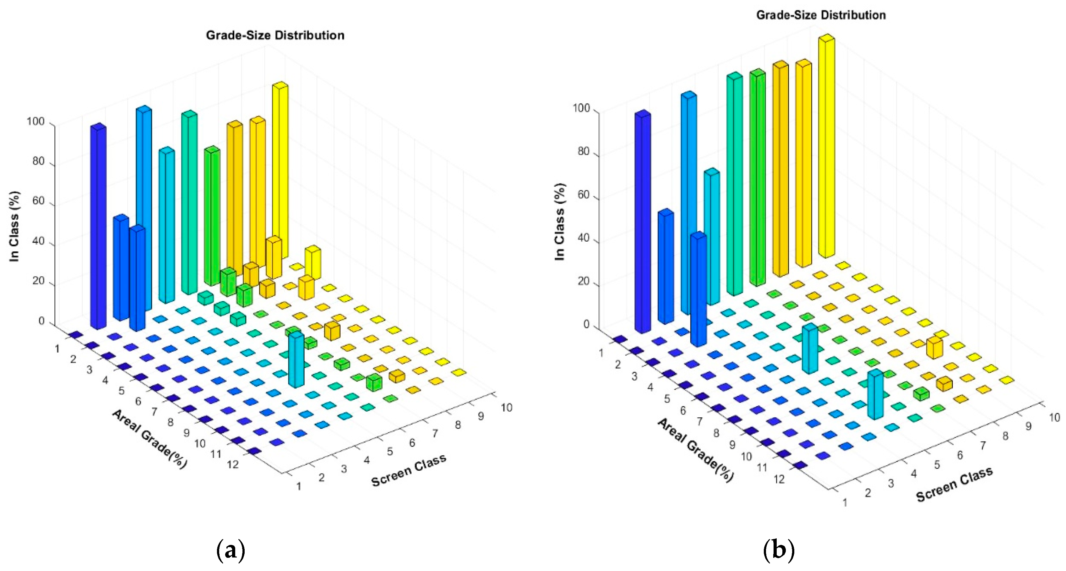
As it can be observed in Figure 2, Figure 3 and Figure 4, the application of each of the random and preferential breakage algorithms generates different shapes of mixed particles and ultimately different PSDs and liberation spectrums. The simulator is able to combine different breakage patterns (transgranular, intergranular, preferential and detachment) on one simulated matrix.

2.2. Validation

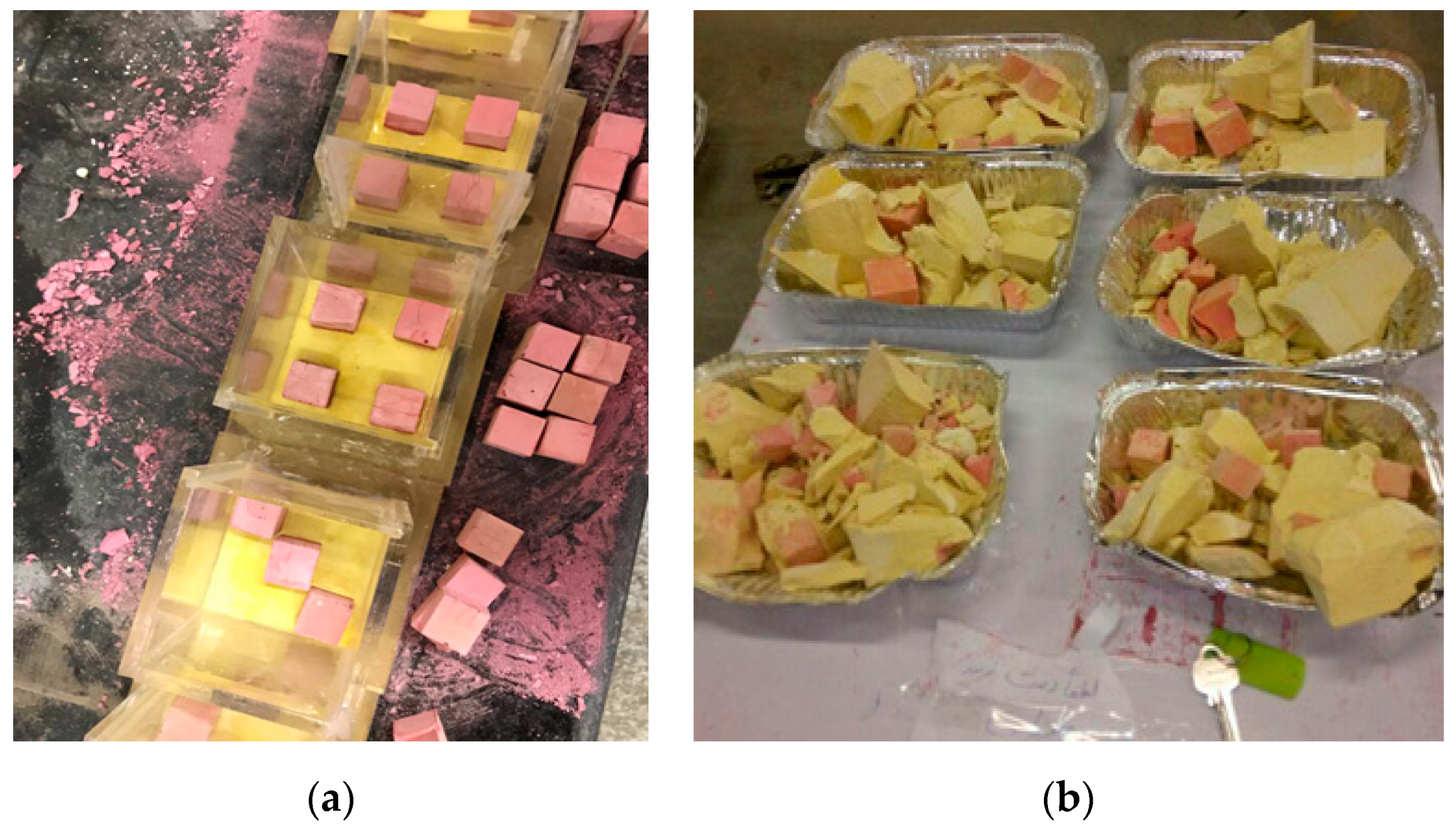
Artificial two-phase stones were used to validate the simulator’s performance, as it has been practiced in the field of mineral liberation studies before [9,35,36,37,38] to overcome the variability and uncertainty in liberation behavior of the real ores. These stones included cubes of size 3 × 3 × 3 cm in red color which were emplaced in a gangue matrix of 7 × 7 × 7 cm of yellow color with a special pattern (Figure 5a,b). In all samples, the matrix was made of dental plaster, while the mineral grains were made of cement or dental plaster. Preliminary results showed that bonding of plaster grains to the plaster matrix is weak compared to the adhesion of cement grains to the plaster matrix. Therefore, the choice of such materials could result in different proportions of intergranular breakages.
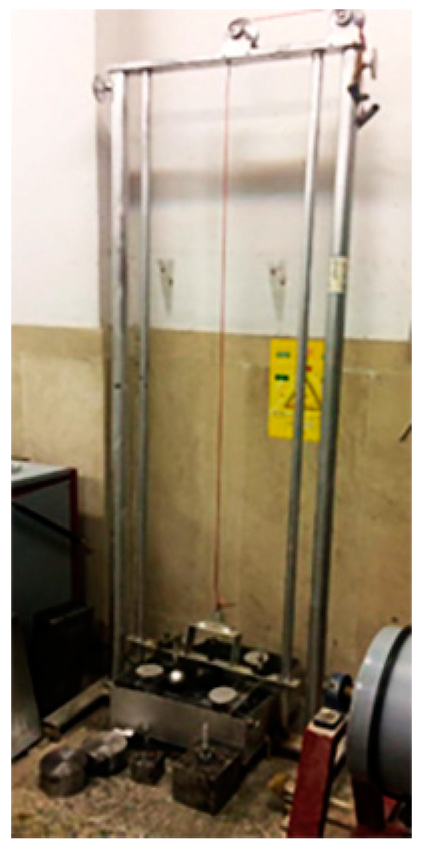
These stones were made in three volumetric grades of 18, 36 and 55 percent. To obtain suitable resistance, it took 10 days to dry the grains and then they were emplaced in the matrix. Later, each specimen was brought out of the mold and crushed by a simple drop weight device designed and made for this research (Figure 6) in two levels of energy (117.2 and 102 kJ). This device consisted of two vertical bars which controlled the path of the crushing media and did not permit it to deviate from a straight-line path.
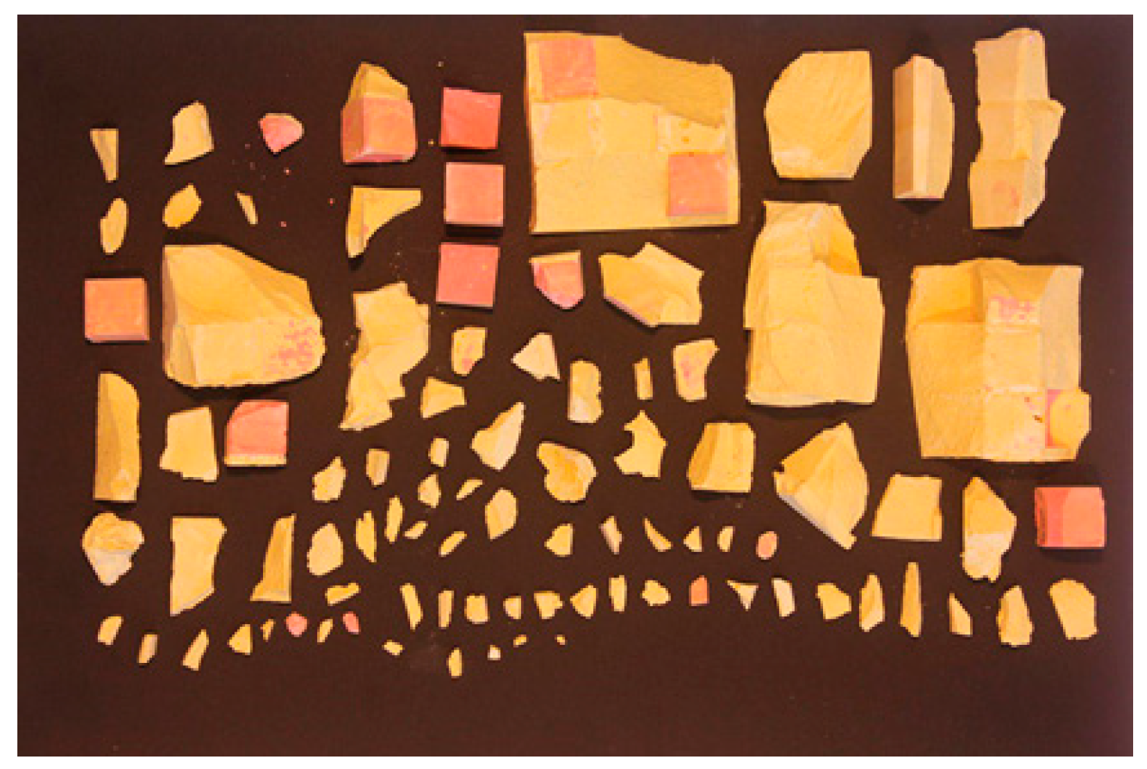
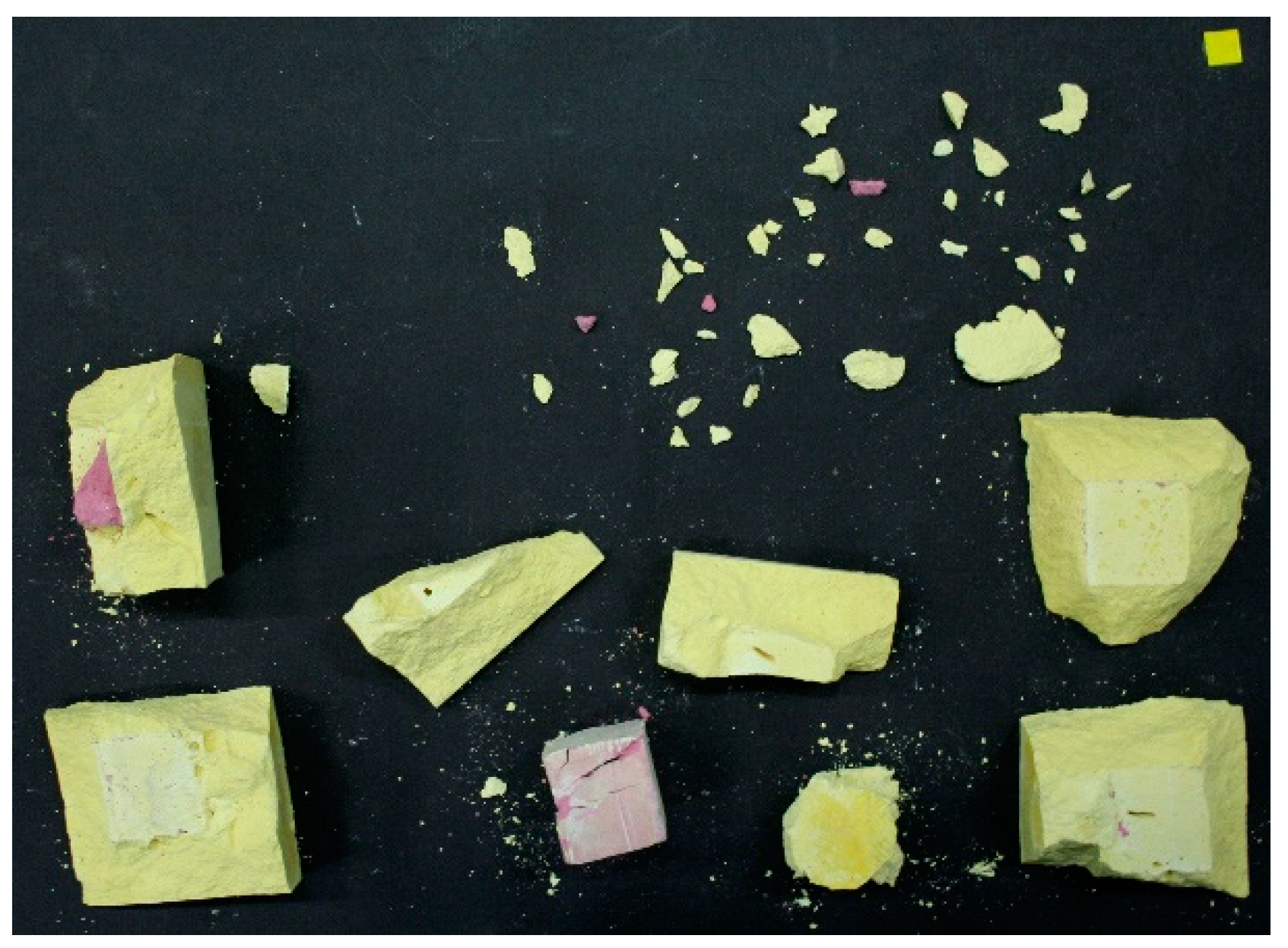
In the next stage, all crushed particles were placed on a black background (Figure 7), and using a digital camera, some images were taken. Crushed particles were manually rotated several times to expose their different sides to enhance the image analysis. Codes have been developed in Matlab in order to analyze the images taken from crushed samples. After initial image-enhancement techniques, these images were stored as binary entities for each phase (valuable and gangue). Then the boundaries of these objects were detected using edge-detection functions. In the next step, neighboring objects with common borders were detected and the size of the interfacial area (IA) between them was determined, as explained in the introduction, based on the methodology developed by Leiβner. By dividing this variable to the known area of the valuable phase, PSIA was determined. This was done for all particles. Two other variables including PSFS and PSSA were also calculated by codes implemented on images. More details about the procedure and validation of the image processing methodology is reported somewhere else [39].
To avoid the generation of completely locked grains that cannot be captured on images, the size of the grains within the artificial stone and the energy level of crushing and therefore the size of crushed particles were chosen carefully so that no grain was completely locked and covered and missed in the images. It is notable that since the two-dimensional data are compared with the two-dimensional simulator’s result and no dimensional change has been made in the data, no stereological corrections were made, while such serological biases are well studied by researchers [33,38,40,41].

3. Results

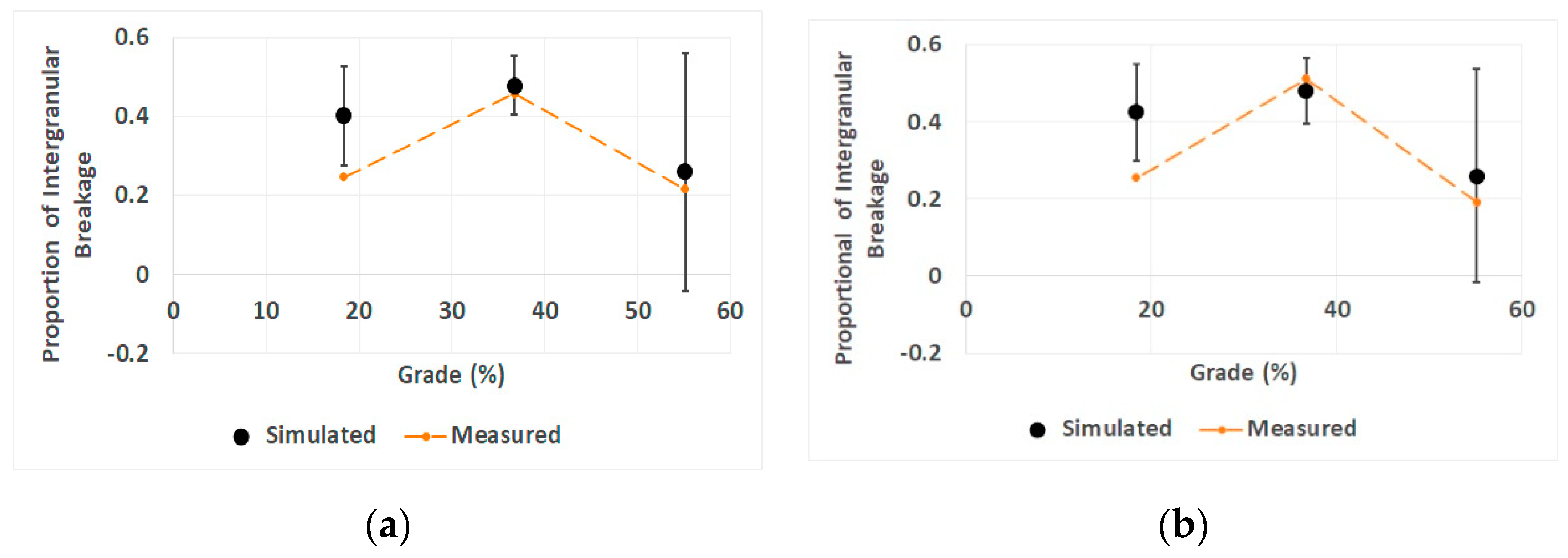
For specimens whose grains and matrix were plaster (weak adhesion of phases), and therefore it was supposed that the intergranular breakage would be dominant, different scenarios were simulated and validated by the experiments. The proportions of intergranular breakage measured by Leiβner’s method both on the simulated fragmented particles and also on images taken from crushed artificial ore were compared for validation purposes. As shown in Figure 8, as the grade of the ore is increasing, the proportion of the intergranular breakage is changing with an agreement between both simulations and experiments.
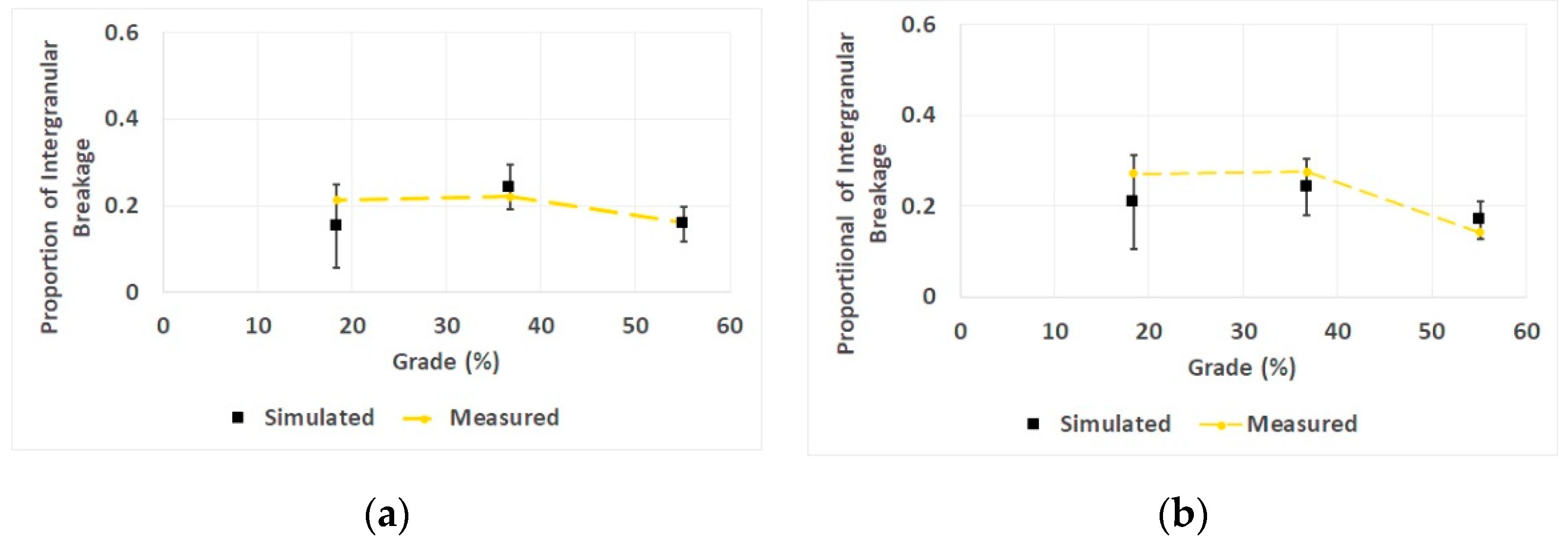
Simulations were also carried out for specimens whose grains were made from cement. The comparison between simulation and experimental results is shown in Figure 9.
The process of generation of seeds and then the Voronoi polygons around the seeds is random. Therefore, 10 simulation runs were simulated and the proportion of inter/transgranular breakages were measured on every simulated graph based on the Leiβner’s methodology and then an average value along with a standard deviation was obtained, which was used to draw the error bars. Error bars in the highest grade (55%) of Figure 8 show more variation compared to other grades, but the average values from simulations are very similar to real results, and also the trends are similar. Results of Figure 9 are more robust, as all the experimental results fall in the range of error bars and no aggressive fluctuations were observed in 10 repetitive simulations.
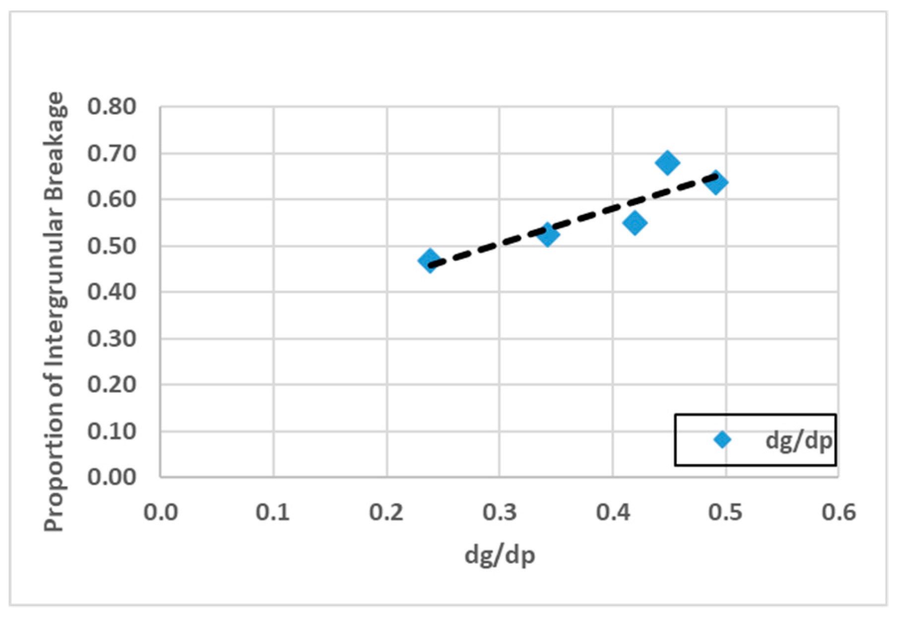
After the validation of the simulator, the effect of the ratio of grain size (dg) to particle size (dp) on the contribution of intergranular breakage was investigated. Five ores with different dg to dp were simulated and the results showed that by increasing the grain size to particle size ratio, the percentage of intergranular fracture increases (Figure 10).

4. Discussion

Such a dependency between the contribution of intergranular breakage and the grade of the ore (as shown in Figure 8) has not been reported before. It seems that in low and high grades, more transgranular breakage occurs, as in the first case most of the cracks are in the matrix with random breakage patterns; and in the second case, due to the high number of valuable grains, cracks have a higher chance of entering a grain and, therefore, again the contribution of transgranular breakage increases. However, in a certain grade, the contribution of intergranular breakage is maximum, which leads to better liberation of grains. Interestingly, this trend is independent of the size of particles (energy level) and the maximum proportion of intergranular breakage has occurred in the same grade in different levels of grinding. Measurements confirm that the simulations are better in middle and high-grade cases, while the simulator’s prediction is deviated for the low-grade case. In low-grade ores, the simulator proposes more intergranular breakages while experimental results show less. However, the trend of changes is comparable in simulations and experiments.
For specimens whose grains were made from cement, it can be seen that the simulator has succeeded in predicting the trend and the measured values of intergranular breakage’s contribution (Figure 9a,b). Besides, the contribution of intergranular breakage is less than the case of plaster grains (maximum value around 0.3 of this case compared to 0.5 of the previous case). In this case, the grain and the matrix material are different, and more preferential breakage is expected, but it is observed that less preferential breakages have occurred. It seems that better bonding of grains to the matrix resulted in less intergranular breakage in this case compared to the case in which the matrix and the grains were the same, but the bonding was weak.
As can be seen in Figure 9, at low grades, the simulator predicts the proportion of intergranular breakage to be less than what it is in reality. It is noteworthy that in low-grade samples, some cases of complete detachment of red grains were observed in experimental results (Figure 11).

5. Conclusions

In this research, a two-dimensional simulator of fragmentation was developed based on the Voronoi tessellation method in the MATLAB environment to simulate random and non-random breakages and the resulting liberation. The simulations were validated using artificial ore samples made in the laboratory in different grades and crushed in different levels of energy. It was observed that the simulator could well predict the changes in the proportion of the intergranular breakage, while the grade and particle size of fragmented material changes. It was observed experimentally that in a certain artificial ore with certain materials of grains and matrix, the proportion of intergranular breakage is dependent on the grade of the ore, but independent of the size of the fragmented particles. This was confirmed by simulations too. In order to be able to verify the simulations, simple textures were used in this paper; however, any texture could be fed to the simulator as a processed image, showing the boundary of minerals. The developed simulator overcomes the complexity of models of non-random breakages and liberation using direct geometric predictions instead of mathematical modeling.

Author Contributions

Writing—Original Draft, Z.S.M.; Writing—Review & Editing, M.R.K.

Funding

This research was funded by Tarbiat Modares University, Tehran, Iran and received no external funding. The APC was funded personally by the authors.

Acknowledgments

The authors thank Thomas Leiβner of the Institute of Mechanical Process Engineering and Mineral Processing, Technische Universität Bergakademie Freiberg, Germany for his sincere guidance in application of his method in this paper.

Conflicts of Interest

The authors declare no conflict of interest.

References

  1. Leißner, T.M.; Mütze, T.; Bachmann, K.; Rode, S.; Gutzmer, J.; Peuker, U.A. Evaluation of mineral processing by assessment of liberation and upgrading. Miner. Eng. 2013, 53, 171–173. [Google Scholar] [CrossRef]
  2. Bole, J.; Lin, C.L.; Miller, J.D. Experimental verification of the PARGEN simulator for liberation analysis. Int. J. Miner. Process. 1993, 37, 209–221. [Google Scholar] [CrossRef]
  3. Herbst, J.A.; Rajamani, K.; Lin, C.L.; Miller, J.D. Development of a multicomponent-multisize liberation model. Miner. Eng. 1988, 1, 97–111. [Google Scholar] [CrossRef]
  4. Gay, S. A liberation model for comminution based on probability theory. Miner. Eng. 2004, 17, 525–534. [Google Scholar] [CrossRef]
  5. Wills, B.; Atkinson, K. Some observations on the fracture and liberation of mineral assemblies. Miner. Eng. 1993, 6, 697–706. [Google Scholar] [CrossRef]
  6. Hsih, C.S.; Wen, S.B. An extension of Gaudin’s liberation model for quantitatively representing the effect of detachment in liberation. Int. J. Miner. Process. 1994, 42, 15–35. [Google Scholar] [CrossRef]
  7. King, R.P. Modeling and Simulation of Mineral Processing Systems; Butterworth-Heinemann: Oxford, UK, 2001. [Google Scholar]
  8. Gaudin, A. Principles of Mineral Dressing; McGraw-Hill: New York, NY, USA, 1939. [Google Scholar]
  9. Klimpel, R.R.; Austin, L.G. A Preliminary Model of Liberation from a Binary System. Powder Technol. 1983, 34, 121–130. [Google Scholar] [CrossRef]
  10. Wiegel, R.L. A random model for mineral liberation by size reduction. Trans. AIME 1967, 238, 179–189. [Google Scholar]
  11. King, R.P.; Schneider, C.L. Mineral liberation and the batch communition equation. Miner. Eng. 1998, 11, 1143–1160. [Google Scholar] [CrossRef]
  12. Mariano, R.; Evans, C.; Manlapig, E. Definition of random and non-random breakage in mineral liberation-A review. Miner. Eng. 2016, 94, 51–60. [Google Scholar] [CrossRef]
  13. Sutherland, D.; Fandrich, R. Selective fracture and liberation of minerals. In Proceedings of the Chemeca 96: Excellence in Chemical Engineering: 24th Australian and New Zealand Chemical Engineering Conference and Exhibition, Sydney, Australia, 30 September–2 October 1996; pp. 83–88. [Google Scholar]
  14. Wills, B.A.; Finch, J. Wills’ Mineral Processing Technology: An Introduction to the Practical Aspects of Ore Treatment and Mineral Recovery; Butterworth-Heinemann: Oxford, UK, 2015. [Google Scholar]
  15. Bérubé, M.A.; Marchand, J.C. Evolution of the mineral liberation characteristics of an iron ore undergoing grinding. Int. J. Miner. Process. 1984, 13, 223–237. [Google Scholar] [CrossRef]
  16. Revnivtsev, V.K.; Ye, P.; Finkelstein, G.A.; Zarogatsky, L.P.; Ivanov, N.A.; Blekhman, I.I.; Ivanov, B.G. Selective liberation of minerals in inertial cone crushers. Powder Technol. 1984, 38, 195–203. [Google Scholar] [CrossRef]
  17. Austin, L.G.; Luckie, P.T. The problems of quantifying mineral liberation: A review. Part. Part. Syst. Charact. 1988, 5, 122–129. [Google Scholar] [CrossRef]
  18. Laslett, G.; Sutherland, D.; Gottlieb, P.; Allen, N. Graphical assessment of a random breakage model for mineral liberation. Powder Technol. 1990, 60, 83–97. [Google Scholar] [CrossRef]
  19. Choi, W.; Adel, G.; Yoon, R. Liberation modeling using automated image analysis. Int. J. Miner. Process. 1988, 22, 59–73. [Google Scholar] [CrossRef]
  20. Fandrich, R.G.; Bearman, R.A.; Boland, J.; Lim, W. Mineral liberation by particle bed breakage. Miner. Eng. 1997, 10, 175–187. [Google Scholar] [CrossRef]
  21. Garcia, D.; Lin, C.L.; Miller, J.D. Quantitative analysis of grain boundary fracture in the breakage of single multiphase particles using X-ray microtomography procedures. Miner. Eng. 2009, 22, 236–243. [Google Scholar] [CrossRef]
  22. Xu, W.; Dhawan, N.; Lin, C.L.; Miller, J.D. Further study of grain boundary fracture in the breakage of single multiphase particles using X-ray microtomography procedures. Miner. Eng. 2013, 46, 89–94. [Google Scholar] [CrossRef]
  23. King, R.P. Calculation of the liberation spectrum in products produced in continuous milling circuits. In Proceedings of the 7th European Symposium on Comminution, Ljubljana, Slovenia, 12–14 June 1990; pp. 429–444. [Google Scholar]
  24. Little, L.; Mainza, A.N.; Becker, M.; Wiese, J.G. Using mineralogical and particle shape analysis to investigate enhanced mineral liberation through phase boundary fracture. Powder Technol. 2016, 301, 794–804. [Google Scholar] [CrossRef]
  25. Leißner, T.; Hoang, D.; Rudolph, M.; Heinig, T.; Bachmann, K.; Gutzmer, J.; Schubert, H.; Peuker, U. A mineral liberation study of grain boundary fracture based on measurements of the surface exposure after milling. Int. J. Miner. Process. 2016, 156, 3–13. [Google Scholar] [CrossRef]
  26. Tanemura, M.; Ogawa, T.; Ogita, N. A new algorithm for three-dimensional voronoi tessellation. J. Comput. Phys. 1983, 51, 191–207. [Google Scholar] [CrossRef]
  27. Machado Leite, M.R. Liberation by size reduction. Consequences and improvements on flotation kinetics. In Innovations in Flotation Technology; Springer: Dordrecht, The Netherlands, 1992; pp. 149–170. [Google Scholar]
  28. Vassiliev, P.V.; Ledoux, H.; Gold, C. Modeling Ore Texture and Mineral Liberation Using 3D Voronoi Diagrams. In Proceedings of the International Conference “Numerical Geometry, Grid Generation and High Performance Computing”, Moscow, Russia, 10–13 June 2008; pp. 10–13. [Google Scholar]
  29. Khalesi, M.R.; Bazin, C.; Hodouin, D.; Bellec, S. A grinding-liberation model for the size reduction of gold ores. In Proceedings of the World Gold Conference, Johannesburg, South Africa, 26–30 October 2009. [Google Scholar]
  30. Khalesi, M.R.; Bazin, C.; Hodouin, D.; Bellec, S. Simulation of gold grain exposure of ground ore using Voronoi tessellation. IFAC Proc. Vol. 2009, 42, 43–48. [Google Scholar] [CrossRef]
  31. Rozenbaum, O.; Machault, J.; Le Trong, E.; Tankeu, Y.G.N.; Barbanson, L. Ore fragmentation modelling for the evaluation of the liberation mesh size. In Proceedings of the 13th SGA Biennal Meeting, Nancy, France, 24–27 August 2015; pp. 1447–1450. [Google Scholar]
  32. Van der Wielen, K.P.; Rollinson, G. Texture-based analysis of liberation behaviour using Voronoi tessellations. Miner. Eng. 2016, 89, 93–107. [Google Scholar] [CrossRef]
  33. Ueda, T.; Oki, T.; Koyanaka, S. A general quantification method for addressing stereological bias in mineral liberation assessment in terms of volume fraction and size of mineral phase. Miner. Eng. 2018, 119, 156–165. [Google Scholar] [CrossRef]
  34. Mirzaei, Z.S.; Khalesi, M.R. Liberation Analysis Using a New Simulator of Random and non-Random Breakage. In Proceedings of the 16th International Mineral Processing Symposium (IMPS 2018), Antalya, Turkey, 23–25 October 2018. [Google Scholar]
  35. Johnston, I.W.; Choi, S.K. Synthetic soft rock for laboratory model studies. Int. J. Rock Mech. Min. Sci. Geomech. Abstr. 1986, 23, 251–263. [Google Scholar] [CrossRef]
  36. Kiss, L.; Schönert, K. Liberation of two-component material by single particle compression and impact crushing. Aufbereitungs-Technick 1980, 5, 223–230. [Google Scholar]
  37. Woollacott, L.C.; Valenta, M. Use of synthetic ore particles to test a transformation function in liberation analysis. Miner. Eng. 1996, 9, 1017–1032. [Google Scholar] [CrossRef]
  38. Ueda, T.; Oki, T.; Koyanaka, S. Experimental analysis of mineral liberation and stereological bias based on X-ray computed tomography and artificial binary particles. Adv. Powder Technol. 2018, 29, 462–470. [Google Scholar] [CrossRef]
  39. Rezvani, A.; Khalesi, M.R.; Mirzaei, Z.S.; Albijanic, B. A simple method for determination of liberation spectrum of high-grade ores by images analysis of crushed particles. Adv. Powder Technol. 2019. submitted. [Google Scholar]
  40. Ueda, T.; Oki, T.; Koyanaka, S. Statistical effect of sampling particle number on mineral liberation assessment. Miner. Eng. 2016, 98, 204–212. [Google Scholar] [CrossRef]
  41. Ueda, T.; Oki, T.; Koyanaka, S. Numerical analysis of the general characteristics of stereological bias in surface liberation assessment of ore particles. Adv. Powder Technol. 2018, 29, 3327–3335. [Google Scholar] [CrossRef]
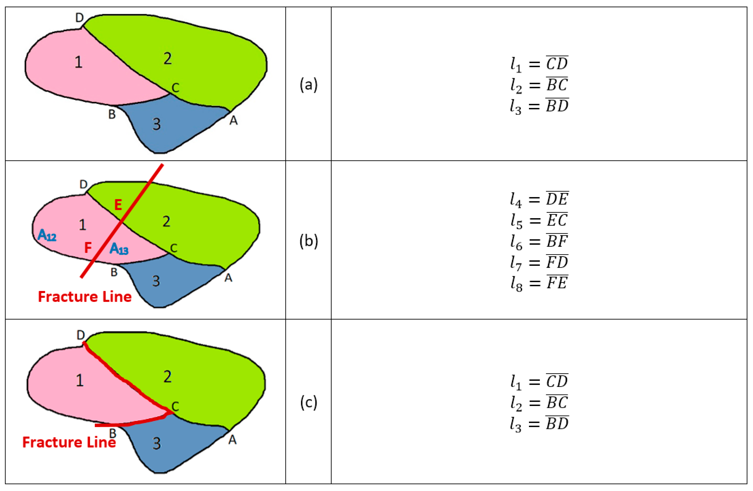
Figure 1. (a) A particle containing three phases with phase 1 as the valuable mineral; (b) transgranular breakage occurs, dividing the particle and phase 1 into two bodies; (c) intergranular breakage occurs, detaching phase 1.
Minerals 09 00341 g001
Figure 2. (a) Generation of Voronoi diagrams (as propagated cracks) on a virtual two-phase ore (red phase as matrix and yellow phase as grains); (b) the shape of mixed particles after random breakage, (c) the shape of mixed particles after preferential breakage.
Minerals 09 00341 g002
Figure 3. (a) PSD of produced particles in random breakage of ore of Figure 2; (b) PSD of produced particles in preferential breakage of ore of Figure 2.
Minerals 09 00341 g003
Figure 4. (a) Liberation spectrum of random breakage of ore of Figure 2; (b) liberation spectrum of preferential breakage of ore of Figure 2.
Minerals 09 00341 g004
Figure 5. (a) Making artificial two-phase ores; (b) crushed two-phase artificial ores.
Minerals 09 00341 g005
Figure 6. The drop weight device.
Minerals 09 00341 g006
Figure 7. Preparing the crushed particles on a black background for taking images.
Minerals 09 00341 g007
Figure 8. Dependency of contribution of intergranular breakage on the grade of the ore with plaster grains; (a) energy level of 117.2 (kJ), (b) energy level of 102 (kJ).
Minerals 09 00341 g008
Figure 9. Dependency of contribution of intergranular breakage on the grade of the ore with cement grains; (a) energy level of 117.2 (kJ), (b) energy level of 102 (kJ).
Minerals 09 00341 g009
Figure 10. Increasing the proportion of intergranular breakage by increasing the grain size to particle size ratio (dg/dp).
Minerals 09 00341 g010
Figure 11. Image of crushed low-grade ore with a detached red grain.
Minerals 09 00341 g011