Article

Design to Reduce Cogging Torque and Irreversible Demagnetization in Traction Hybrid Motor Using Dy-free Magnet

1
Department of Electrical Engineering, Hanyang University, Seoul 04763, Republic of Korea
2
Department of Electrical Engineering, Gachon University, Seongnam 13120, Republic of Korea
3
Deptartment of Mechanical, Automotive and Robot Engineering, Halla University, Wonju 26404, Republic of Korea
*
Author to whom correspondence should be addressed.
Machines 2023, 11(3), 345; https://doi.org/10.3390/machines11030345
Submission received: 14 February 2023 / Revised: 24 February 2023 / Accepted: 27 February 2023 / Published: 2 March 2023
(This article belongs to the Special Issue Permanent Magnet Motors: State of the Art)

Abstract

:
The PMSM (Permanent Magnet Synchronous Motor) is being studied a lot in traction motors for high efficiency and high performance. Usually, magnets containing rare earth elements are used. However, since rare earth elements are not suitable for future industries due to their limited reserves, many studies on magnets excluding rare earth elements are being conducted. Magnets excluding rare earth elements have a low coercive force and are vulnerable to irreversible demagnetization, so their design must be robust. Additionally, the design used for reducing the cogging torque, which is a major variable of traction motors, is also important. Therefore, in this study, a design process for reducing irreversible demagnetization and cogging torque is proposed. There are three methods for this process. The first one is the application of the tapering structure, and the second one is the tapering skew structure. The third one is the application of an asymmetric air hole. As a result of these methods, the target irreversible demagnetization ratio was satisfied and the cogging torque was reduced. This was proven through FEA (Finite Element Analysis) and verified by comparing and analyzing the experimental results and simulation results of actual manufacturing.

1. Introduction

Many studies have been conducted on PMSMs (Permanent Magnet Synchronous Motor) for high performance and efficiency [1,2,3,4,5,6]. The permanent magnet used here is made by including rare earth elements in the magnet [7,8]. However, rare earth elements have limited reserves, so they have many disadvantages in the future industry. Therefore, recently, many studies have been conducted on magnets excluding rare earth elements [9,10,11,12]. Magnets that completely exclude rare earth elements are called Dy-free magnets. Dy-free magnets are susceptible to irreversible demagnetization due to low coercive forces. Therefore, if a Dy-free magnet is applied, a design for reducing irreversible demagnetization is required. [13,14,15,16,17]. Additionally, a traction motor is used, and the traction motor is an application that is sensitive to noise and vibration. Therefore, it is necessary to reduce the cogging torque, which is one of the leading causes of these problems [18,19,20,21]. In summary, this study proposes a process that satisfies the target value of irreversible demagnetization and reduces the cogging torque by selecting a traction motor with a Dy-free magnet as the target motor [22]. In this study, three important processes are proposed to reduce the cogging torque and irreversible demagnetization. The first method Is to apply a tapering structure. The second is to apply a tapering skew structure. When the tapering skew structure is applied, asymmetry occurs in the rotor structure, resulting in asymmetry in the cogging torque and back emf. To improve this asymmetry, a two-step tapering skew structure can be applied. To be more precise, the asymmetry is improved by symmetrically applying the tapering skew angle to the upper and lower halves of the rotor stacking halves. The third method is to insert an air hole. By inserting the air hole, the irreversible demagnetization ratio can be reduced. By inserting air holes asymmetrically, the cogging torque can be reduced. Irreversible demagnetization occurs more in the magnet located in the area where the tapering skew structure is not applied than it does in the area where the tapering skew structure is applied. Therefore, by inserting two air holes in the pole piece where the tapering skew structure is applied and one air hole in the other part, the target demagnetization ratio can be satisfied and the cogging torque can be reduced. Figure 1 shows the design process for irreversible demagnetization and cogging torque reduction.

2. Conventional Model Analysis

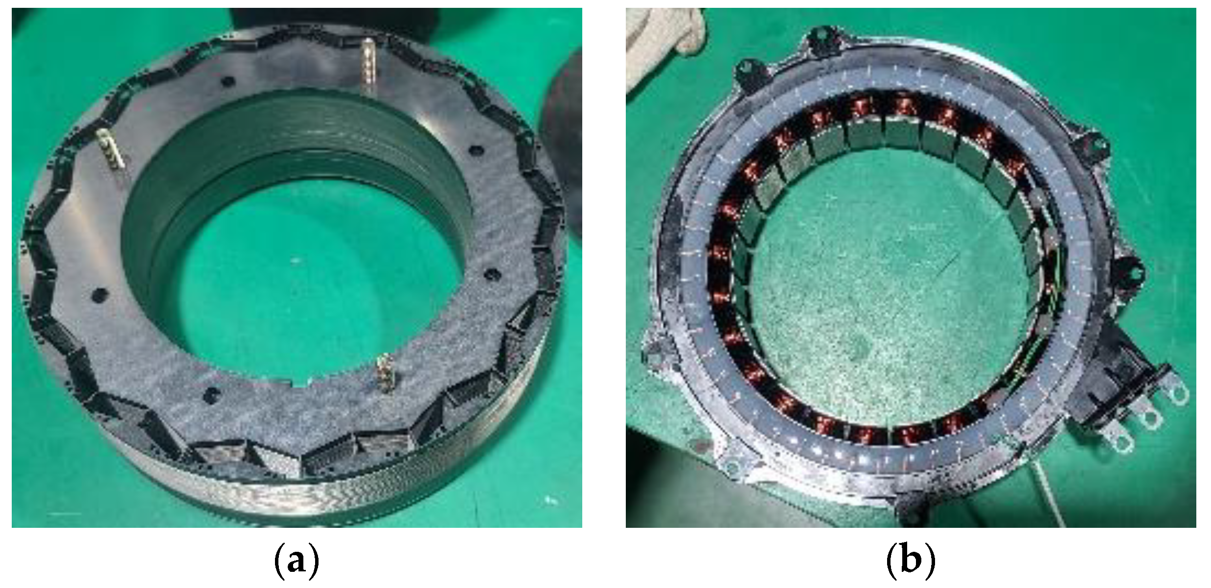
Figure 2 illustrates the manufactured model of the stator and rotor of the hybrid traction motor to which the existing Dy-free magnet was applied. Table 1 shows the specifications of conventional motors.
Figure 3 shows the irreversible demagnetization area of the existing model and the B–H curve of the Dy-free magnet at 150 (°C). After confirming that the coercive force of the Dy-free magnet was low, a design was established to improve the irreversible demagnetization. The irreversible demagnetization was analyzed based on applying 1.2 times the maximum current, and as a result, the irreversible demagnetization ratio was less than 1 (%).
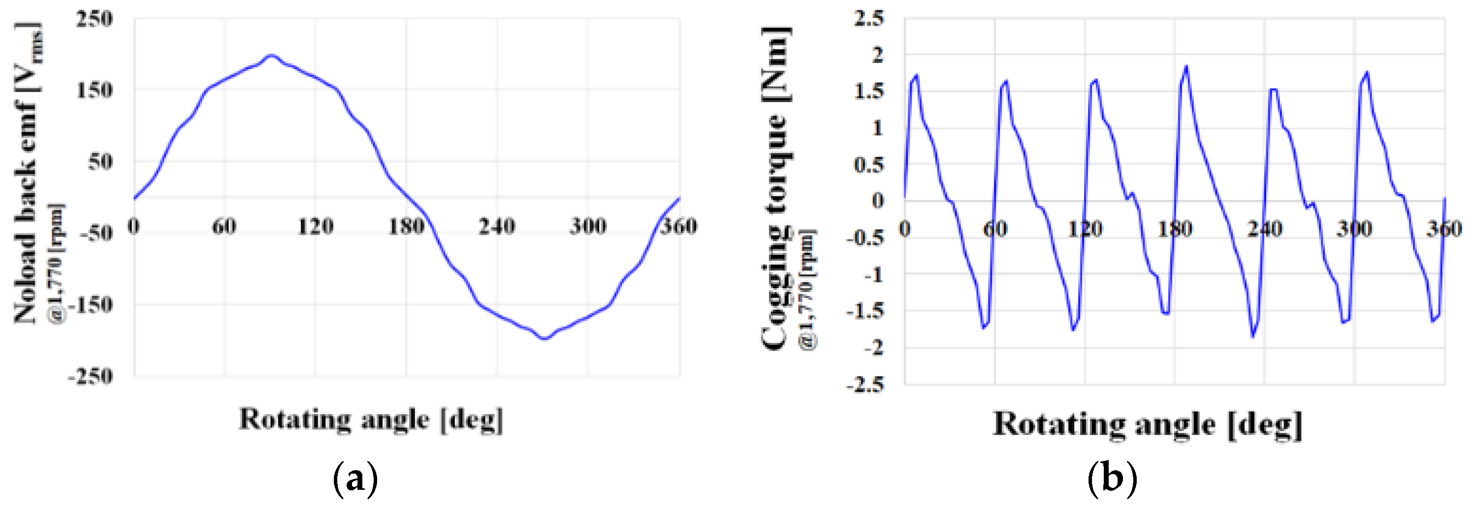
Figure 4 depicts the back emf and cogging torque. In this study, a design was performed to reduce the cogging torque while satisfying the irreversible demagnetization ratio of less than 1(%) during the same performance.

3. A Study on Reducing Cogging Torque and Irreversible Demagnetization through the Application of a Tapering Structure

3.1. Application of Tapering Structure

Figure 5 illustrates the parameters of the tapering structure design. As L t a p increases, the tapering depth increases. The tapering depth is indicated by g ( θ ) . The formula for g ( θ ) is shown in Equation (1).
g ( θ ) = R ( L t a p cos θ + ( R L t a p ) 2 ( L t a p sin ( θ ) 2 ) ) × 2
The formula for θ is shown in Equation (2).
θ = r e m ( θ m + 360 M P × 2 , 360 M P ) 360 M P × 2
The depth of tapering can be calculated using the above two equations. The cogging torque and back emf increase according to Figure 6.
In Figure 6a, it is confirmed that the cogging torque rapidly decreases as L t a p increased, and then gradually increases again from 15 mm. When L t a p is too long, the cogging torque hardly changes. As shown in (b), the back emf continues to decrease as L t a p increases. An increase in L t a p indicates a greater depth of tapering. As L t a p increases, the tapering deepens, and the air gap widens. As a result, when L t a p increases, the performance worsens. In addition, in order to apply Dy-free permanent magnets, the analysis of irreversible demagnetization caused by the low coercive force of Dy-free permanent magnets is essential. Figure 7 shows the irreversible demagnetization ratio depending on L t a p .
As illustrated in Figure 7, as L t a p increases, the irreversible demagnetization ratio increases. This is because the tapering depth, g ( θ ) , increases as L t a p increases. Then, the reverse magnetic field directly affects the magnet. Therefore, when L t a p increases, the irreversible demagnetization ratio increases.

3.2. Application of Tapering skew Structure

As illustrated in Figure 8, the skew angle range was selected as −3.5 ° ~3.5 °. The tapering angle range was specified inside the barrier.
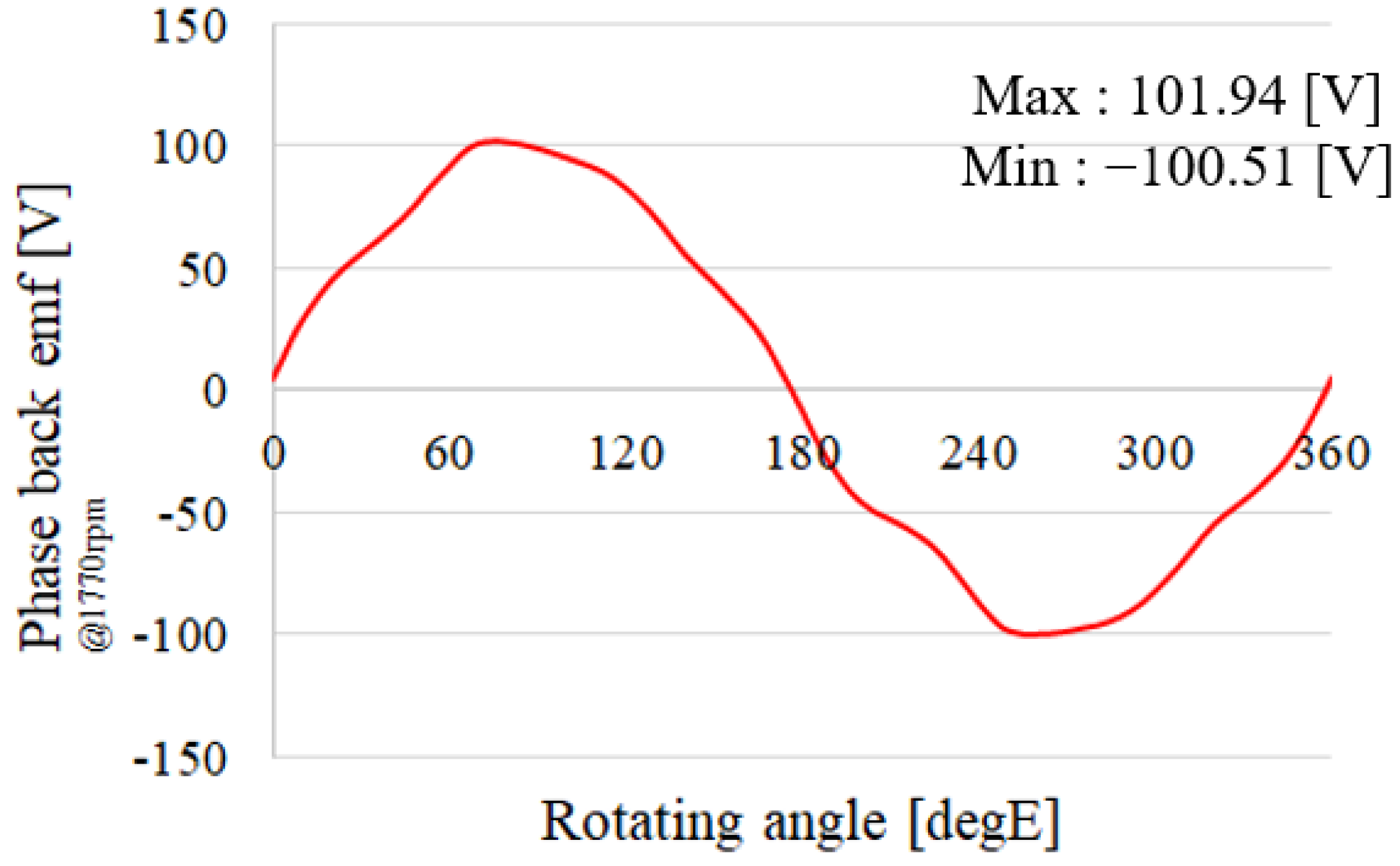
If tapering is applied to the other ranges, the performance worsens. The reason for the deterioration of the performance is that the v-shape type is a type that improves its performance by concentrating the magnetic flux to a pole piece. However, when tapering is applied to the pole piece, air gaps are formed in the area where magnetic flux is concentrated, resulting in a worse performance. Therefore, the range of the tapering skew angle was selected as follows. Figure 9 shows the back emf when the skew angle is 2.5 deg.
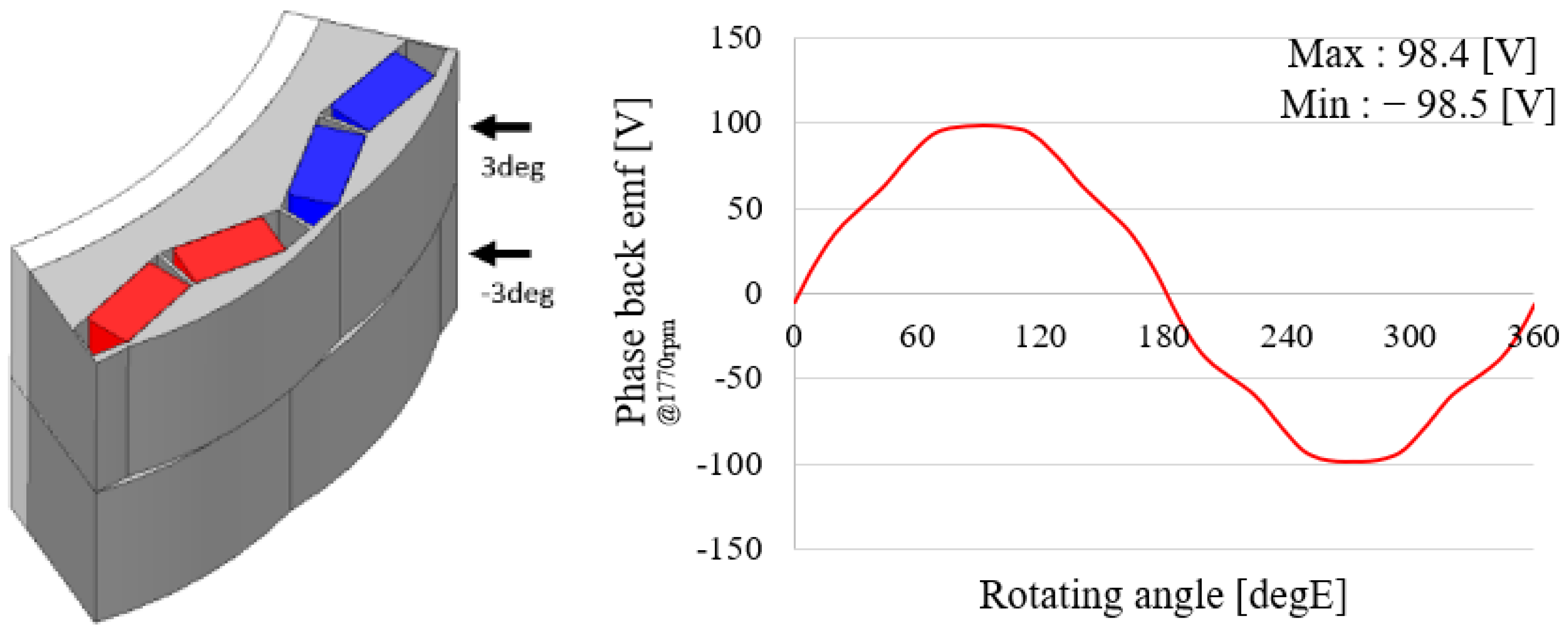
As shown in Figure 9, back EMF asymmetry occurred. Since the tapering skew angle is biased to one side, the maximum value is 101.94 (V) and the minimum value is −100.51 (V), resulting in counter-electromotive force asymmetry. To improve this asymmetry, a two-stage skew angle structure was applied. For example, if half of the laminated length is 3 deg, the other half is −3 deg. For symmetry, a symmetrical combination was selected as above. Figure 10 shows the two-stage skew tapering model and back emf.
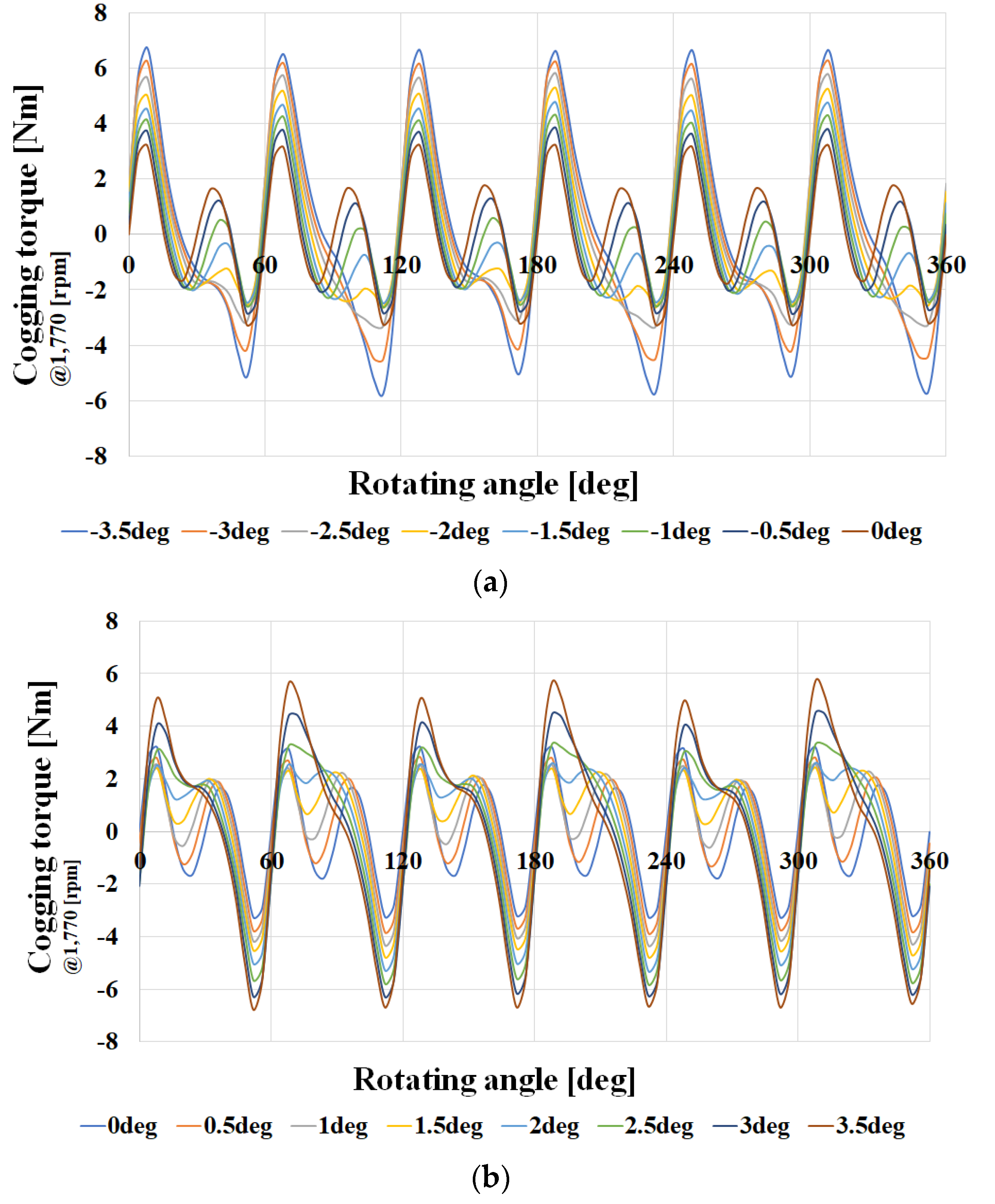
The back emf asymmetry is improved by the symmetrical skew structure of the upper and lower halves of the rotor. When two-stage skew tapering structure is applied, the cogging torque generated in the upper half of the rotor and the cogging torque generated in the lower half are expected to offset each other, thereby reducing the cogging torque. Figure 11 shows the cogging torque when the two-stage skew tapering structure is applied.
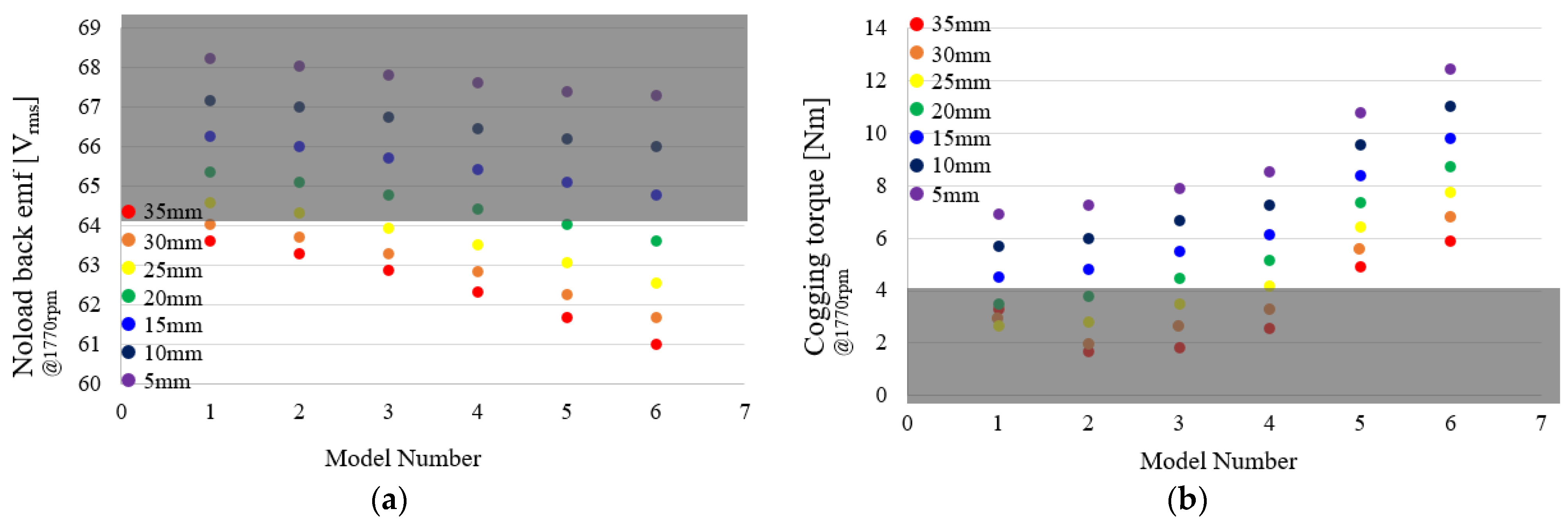
As shown in Figure 11, the cogging torque waveforms of −3.5 deg~0 deg and 0 deg~3.5 deg are reversed. If the upper and lower halves of the rotor are combined at a symmetrical skew angle, the cogging torque will be reduced. Figure 12 shows the back-emf and cogging torque according to the increase in depth. Model 1 is a model in which tapering skew angles of 1 deg and −1 deg are combined. Models 2 to 6 represent the sum of 1.5 deg and −1.5 deg, 2 deg and −2 deg, 2.5 deg and −2.5 deg, 3 deg and −3 deg, and 3.5 deg and −3.5 deg, respectively. As illustrated in Figure 12, the shaded area is the selectable area.
Figure 12a shows the back emf depending on the tapering skew angle. As L t a p increases or the tapering skew angle approaches 3.5 deg, the back emf tends to decrease. Figure 12b shows the cogging torque depending on the tapering skew angle. As L t a p increases, the cogging torque decreases, and when the tapering skew angle increases, the cogging torque shows a different tendency for each model. In the area where the cogging torque is small, it tends to decrease in Model 2, and then slowly increase again. In the area where the cogging torque is small, it shows a tendency to decrease in Model 2, and then slowly increase again. Here, a model that falls within the target range of back emf and cogging torque was selected. Models that fall within the two target ranges are Model 1 and Model 2 when L t a p is 25 mm, and Models 1 and 2 when L t a p is 20 mm. Among them, Model 2 with 25 mm L t a p , which is a combination of 1.5 deg and −1.5 deg is selected. This is because it has a high back emf and low cogging torque. Since a Dy-free magnet with low coercive force was used as the magnet, an irreversible demagnetization analysis was performed according to the tapering skew angle. This is shown in Figure 13.
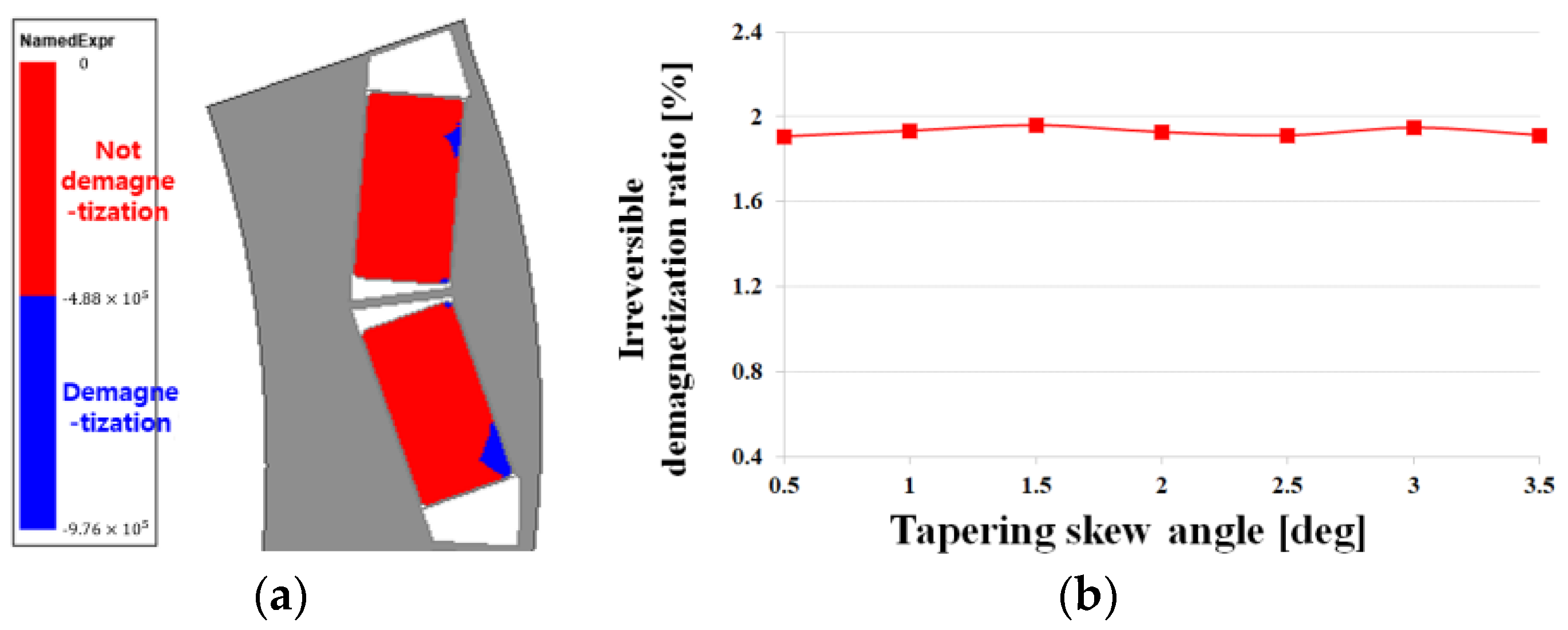
As shown in Figure 13a, irreversible demagnetization occurs less often in the area where tapering is applied than it does in the area where tapering is not applied. This is because irreversible demagnetization occurs due to demagnetization caused by windings. However, irreversible demagnetization occurs less often in the area where tapering is applied because the air gap is larger. Figure 13b shows the irreversible demagnetization ratio according to the tapering skew angle. It can be seen that the irreversible demagnetization does not change significantly depending on the tapering skew angle. In addition, it was confirmed that irreversible demagnetization had no effect on the selection of a model in which the L t a p of the selected model was 25 mm and the tapering skew angle was 1.5 deg and −1.5 deg combined. Afterwards, in this study, an additional reduction design was created to match the irreversible demagnetization ratio and cogging torque to the target performance.

4. Research on Irreversible Demagnetization Ratio and Cogging Torque Reduction through Asymmetric Air Hole Insertion

4.1. Bridge and Barrier Support Structure Design

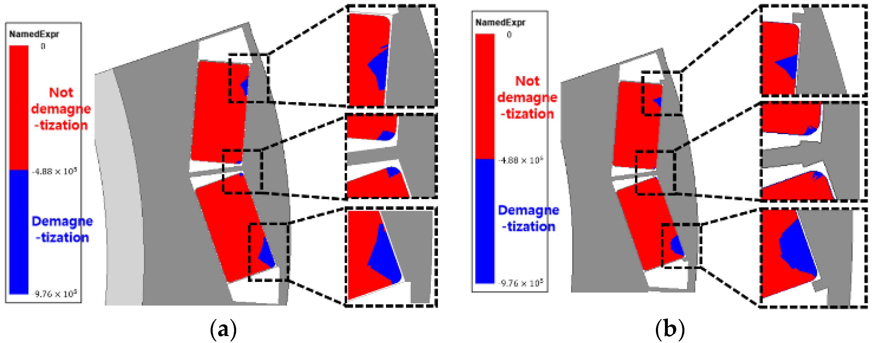
Steel plates were inserted into bridges and barriers to serve as a support structure for the magnets and to reduce the irreversible demagnetization ratio. When a steel plate is inserted, the reverse magnetic field generated by the winding uses the steel plate as a magnetic flux path. Then, the diamagnetic field generated by the windings going to the magnet flows into the steel plate and reduces the irreversible demagnetization ratio. Figure 14 shows the irreversible demagnetization area when steel plates are inserted into the bridges and barriers.
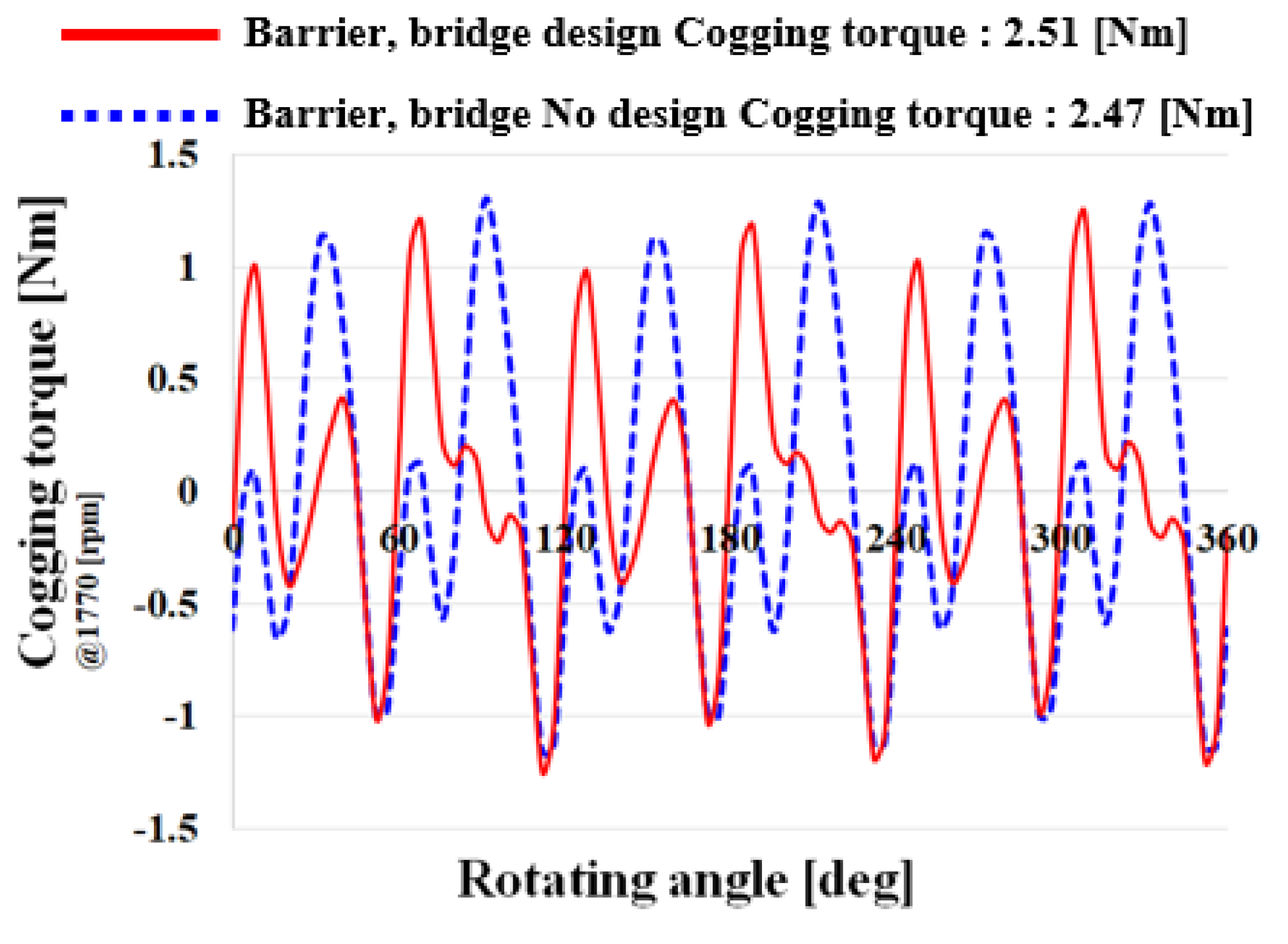
Figure 14 shows the irreversible demagnetization area before and after the steel plate was inserted into the barrier and bridge. Although it was not significantly reduced, there was a slight decrease. A steel plate must be inserted to support the magnet. A steel plate was inserted to reduce irreversible demagnetization as much as possible to perform the role of a magnet support structure and reduce the demagnetization at the same time. Figure 15 illustrates the cogging torque waveforms before and after barrier and bridge design was applied.
As shown in Figure 15, the cogging torque after designing the barrier and bridge was 2.51 (Nm), which increased by 1.5 (%) compared to 2.47 (Nm) before the design was applied. Barrier and bridge designs were applied to reduce the magnet support and irreversible demagnetization ratio, and as a result, the cogging torque increased slightly, but it was confirmed that there was no significant difference.

4.2. Insertion of Air Hole

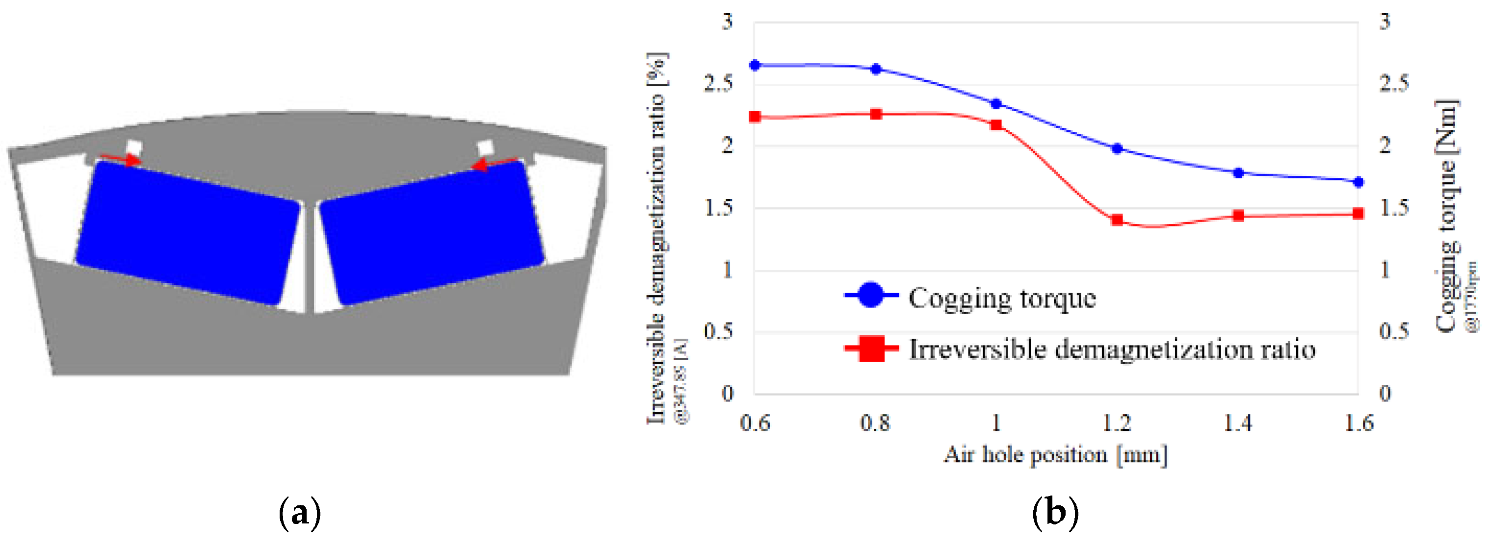
An air hole was inserted in the pole piece to reduce the irreversible demagnetization. If an air hole is inserted in the pole piece in front of the area where irreversible demagnetization occurs a lot, the flow of the reverse magnetic field generated by the winding to the magnet can be reduced. If an air hole is inserted in the pole piece in front of the area where diamagnetic field occurs a lot, the flow of the reverse magnetic field generated by the winding to the magnet can be reduced. In this way, irreversible demagnetization can be reduced. Figure 16 shows the irreversible demagnetization area, cogging torque, and air hole insertion model according to the air hole insertion. Insertion was performed at a distance of 0.6 mm from the magnet pocket side to consider mechanical stiffness.
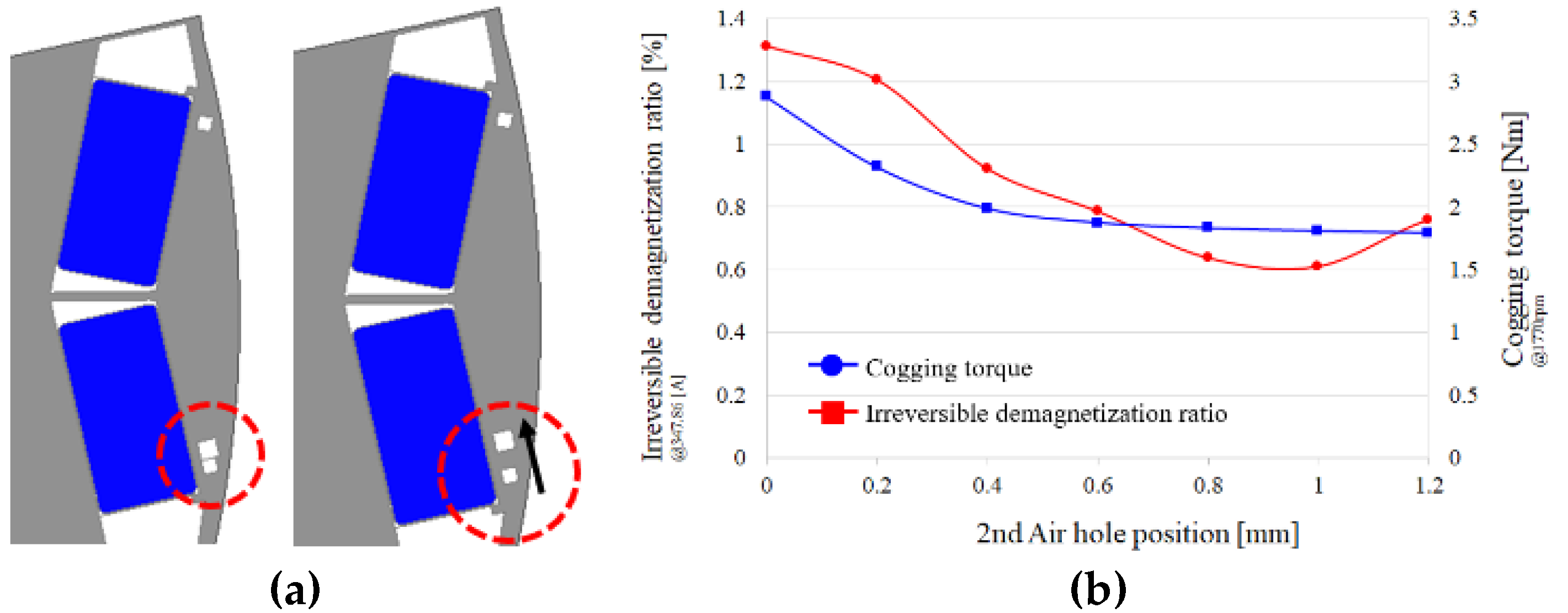
In Figure 16a, an air hole was inserted into the pole piece, and the tendency of the cogging torque and irreversible demagnetization ratio was confirmed as we moved the air hole toward the bridge. The cogging torque decreased as we changed the air hole position. Additionally, the irreversible demagnetization ratio also decreased as the air hole position changed, and it was constant from 1.2 mm. Therefore, the air hole position was set as 1.4 mm. The target cogging torque was satisfied. However, it did not satisfy the most important irreversible demagnetization ratio. So, in order to reduce the irreversible demagnetization ratio, a second air hole was inserted. The second air hole was inserted only on the pole piece side where irreversible demagnetization occurs a lot, and the cogging torque reduction design was applied by shifting the phase of the cogging torque waveform through the air hole asymmetric structure. In addition, the irreversible demagnetization ratio reduction design was performed by inserting an air hole in front of the pole piece where irreversible demagnetization occurs a lot. Figure 17 depicts the asymmetric air hole insertion structure, irreversible demagnetization ratio, and cogging torque graph.
As shown in Figure 17, irreversible demagnetization occurred largely in the part where tapering skew was not applied, so the second air hole was inserted only in the pole piece in front of this magnet. The second airhole was inserted asymmetrically. Figure 17b shows the second cogging torque and irreversible demagnetization ratio. The cogging torque decreases as the second air hole position changes, and it remains constant from 0.4 mm. The irreversible demagnetization ratio decreases as the second air hole position changes, and then increases from 1 mm. The second air hole that satisfies these two target performances was selected as 1 mm. Finally, all the target performances were satisfied. Figure 18 shows a model for an asymmetric air hole structure.
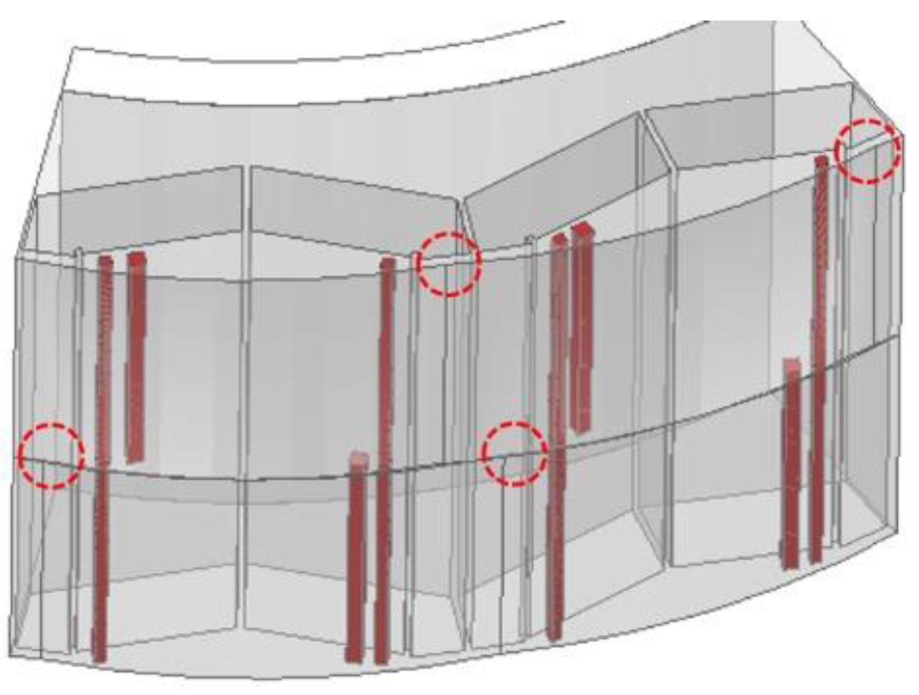
Figure 18 shows the final model, a rotor with an asymmetric air hole structure. The part corresponding to the dotted circle mark is the part to which the tapering skew structure was applied, and the part corresponding to dark color represents the air hole part. If you look at the dark part, you can see the asymmetric structure in the air hole.

5. Electromagnetic and Mechanical Performance Analysis

5.1. Electromagnetic Performance Analysis

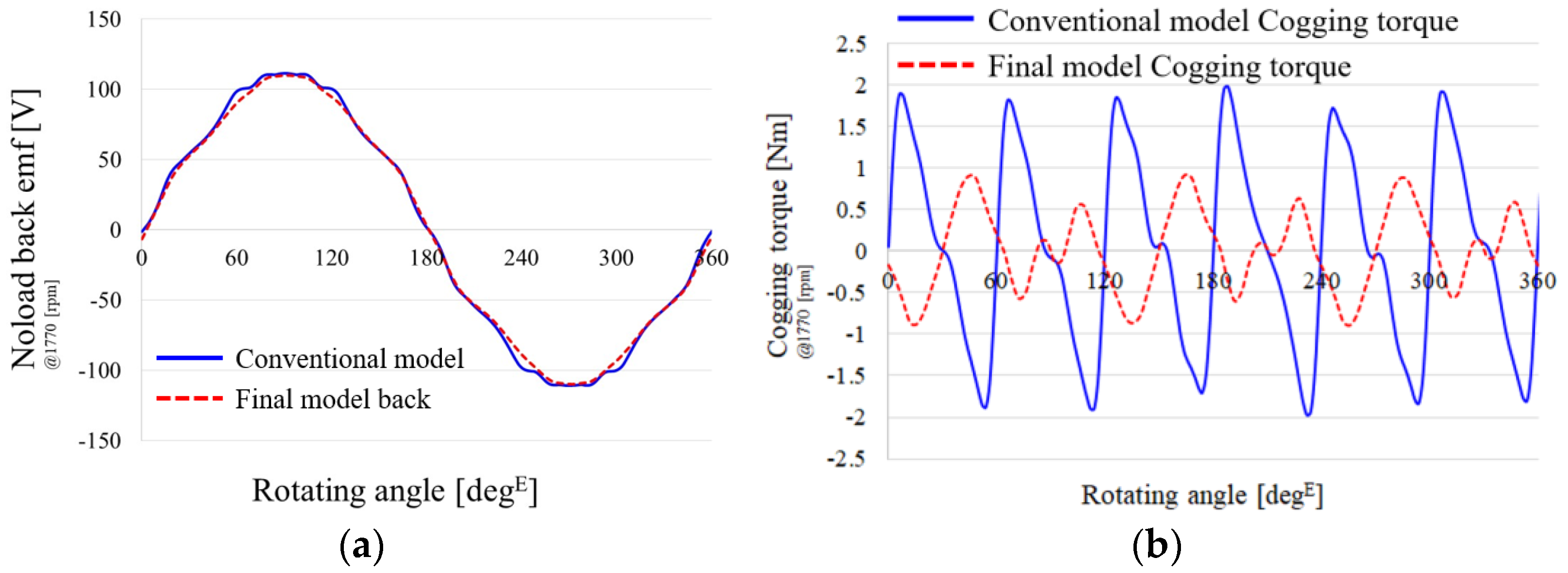
Figure 19 shows the back emf and cogging torque of the conventional model and the final model.
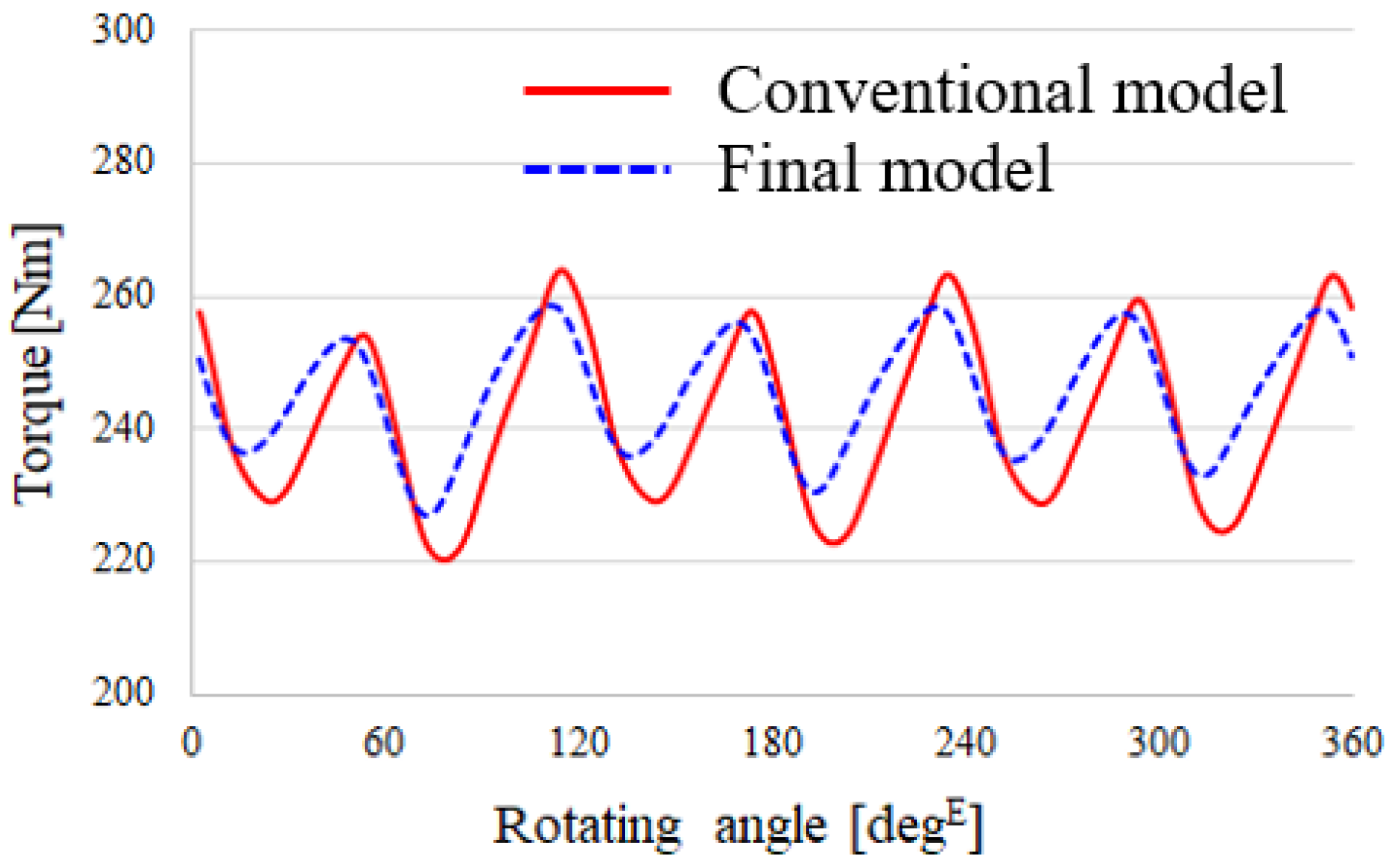
Figure 19a shows the back emf of the two models. The back emf values for both models are almost identical. That is, both models have the same performance. Figure 19b shows the cogging torque. The cogging torque in the conventional model is 3.96 (Nm), and the cogging torque in the final model is reduced to 1.81 (Nm). Figure 20 shows the torque waveform at a speed of 1770 (rpm) and a current of 205 (Arms). The torque ripple in the conventional model is 43.6 (Nm), and the torque ripple in the final model is 29.41 (Nm). The torque ripple of the final model was reduced by 32.5 (%) compared to that of the conventional model. Table 2 shows the main performances of the conventional model and the final model.
The cogging torque of the conventional model is 3.96 (Nm), and the cogging torque of the final model is 1.81 (Nm). That is, the cogging torque of the final model compared to the conventional model was reduced by 54.3(%). The target value of the irreversible demagnetization ratio is within 1%. The irreversible demagnetization ratio in the final model was 0.61%, which was less than 1%. Table 3 shows the losses for the conventional model and the final model. The loss was shown for a speed of 1770 (rpm) and a current of 102.5 (Arms).
Table 3 shows the losses for the conventional model and the final model. Since the final model uses the same stator and designed only the rotor, the copper loss is the same. However, core loss and lac eddy current loss were reduced because tapering was applied in the design of the final model rotor. Compared to the conventional model, the core loss of the final model was reduced by 11.7 (%), and the eddy current loss was reduced by 10.8 (%).

5.2. Mechanical Performance Analysis

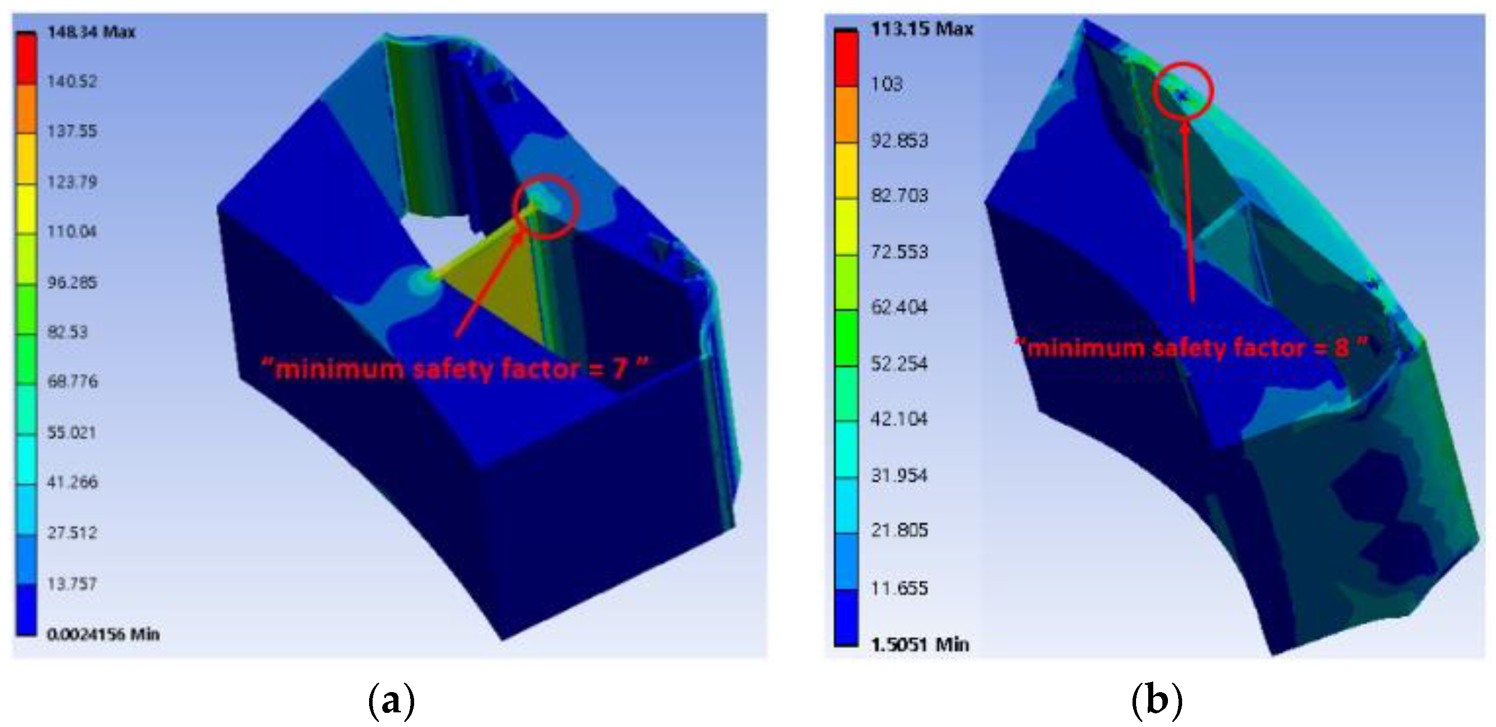
It is important to analyze the electromagnetic performance. However, it is meaningless unless the mechanical rigidity is checked. It is necessary to check whether the mechanical rigidity is satisfied. Figure 21 shows the safety factor for the conventional model and the final model. Both models analyzed the mechanical stiffness in the air hole application state.
Figure 21 showed mechanical stiffness in both models. The equivalent stress in the conventional model is 148.34 (MPa), and the minimum safety factor is seven. The equivalent stress in the final model is 113.15 (MPa), and the minimum safety factor is eight. Compared to the conventional model, it was confirmed that the final model had a lower equivalent stress and a higher minimum safety factor. In other words, it proved that it is mechanically safer than the conventional model is.

6. Experimental Results

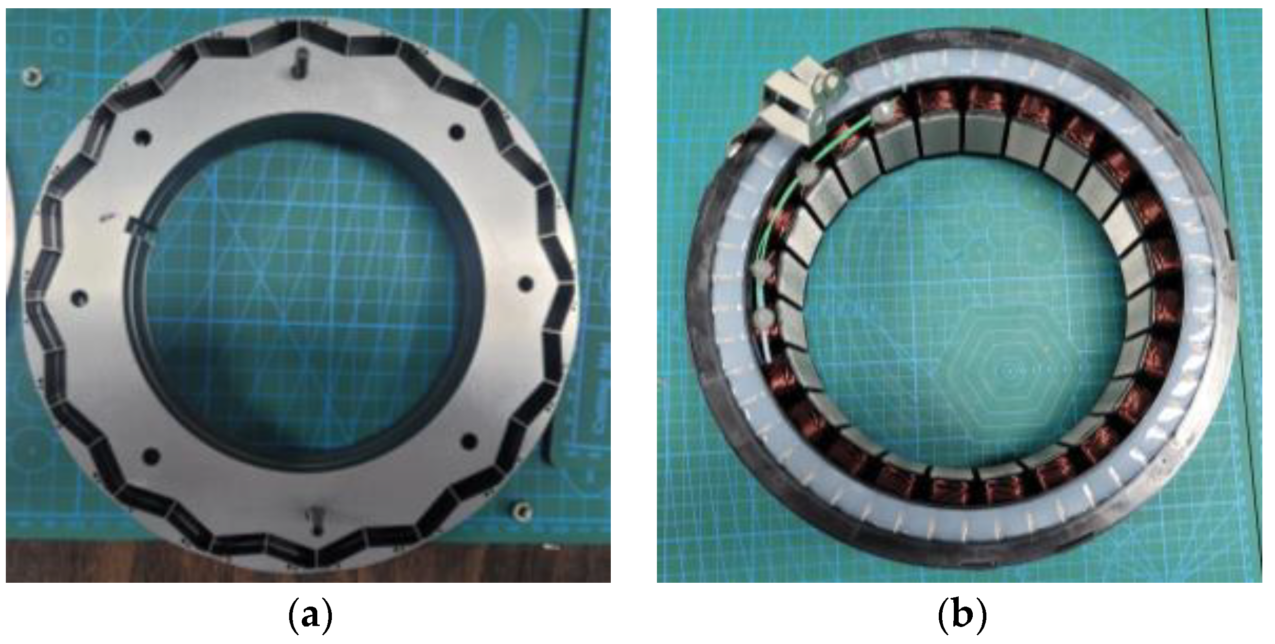
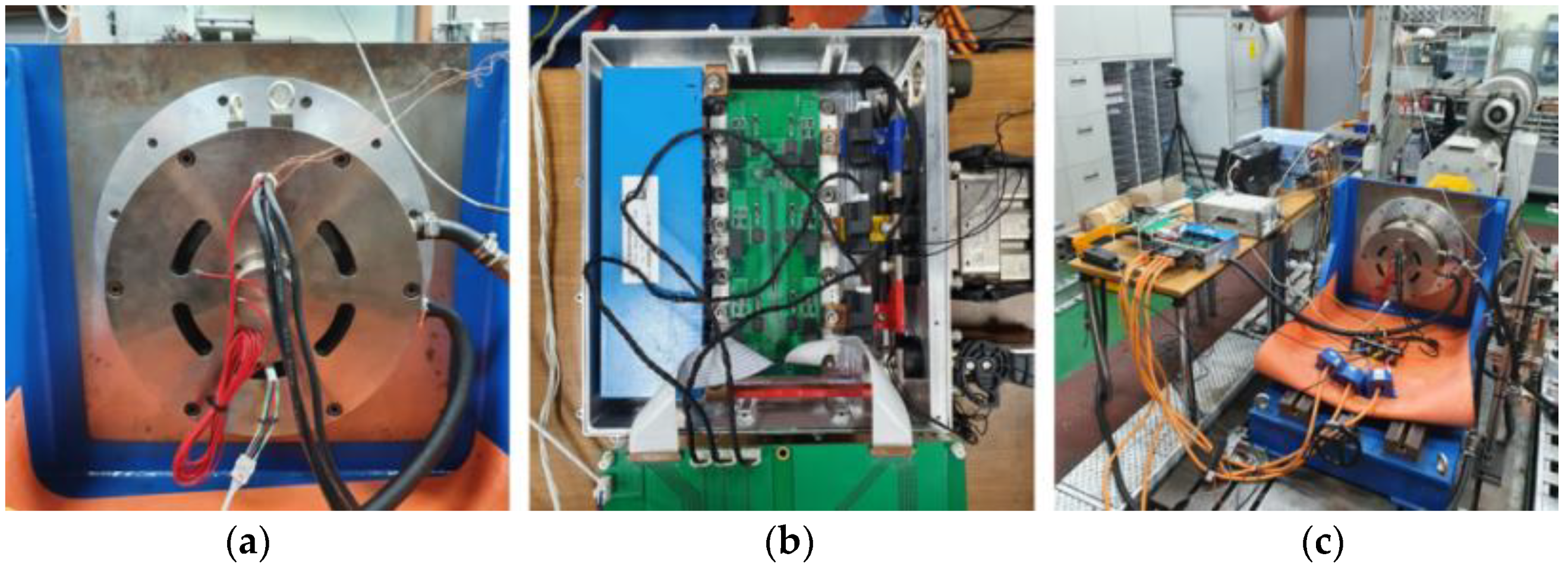
Figure 22 shows the final model rotor and stator. Figure 23 shows pictures of the final prototype, controller, and performance evaluation environment. Figure 24 shows a dynamo test bench combined with a temperature and humidity chamber for analyzing the irreversible demagnetization ratio and a temperature data log. The irreversible demagnetization ratio can be confirmed by looking at the counter electromotive force reduction rate when a reverse magnetic field was applied at a high temperature. The results of the experiment with these experimental equipment are shown below.
Figure 25 shows the current waveform during the maximum output operation of the final model motor and the current waveform during maximum efficiency operation. Table 4 shows the motor torque and maximum output, and Table 5 shows the maximum efficiency test results.
Figure 26 shows the measurement result of the reduction rate of counter-electromotive force of the Dy-free magnet final prototype motor. Table 6 shows the experimental results.
Table 6, it can be seen that the counter electromotive force is reduced by 16.28 (%) at room temperature (20 °C) and at (150 °C).
Figure 27 shows the back emf waveform before applying the demagnetizing current, the back emf waveform after applying the demagnetizing current, and the demagnetizing current. At this time, the temperature condition was 150 °C, the speed was 1000 (rpm), and the applied demagnetization current was measured under the conditions of 554 (Apeak). Additionally, the scale of the back emf test waveform y-axis is 50 (Vrms). At this time, the no-load back emf before applying the demagnetizing current was 40.61 (Vrms), and the no-load back emf after applying the demagnetizing current was 40.51 (Vrms). At this time, the irreversible demagnetization ratio was 0.25 (%).

7. Conclusions

In this paper, a hybrid traction motor with a Dy-free magnet was selected as a target model, and cogging torque and irreversible demagnetization ratio reduction studies were conducted. A Dy-free magnet has a low coercive force and is vulnerable to irreversible demagnetization. Therefore, if a Dy-free magnet is applied, an irreversible demagnetization design is essential. However, the cogging torque of the traction motor is also a design variable that should be considered as a major factor. Therefore, in this paper, a design for reducing the cogging torque and irreversible demagnetization ratio was performed by applying a Dy-free magnet. The design was carried out for the same v-shape type as that of the target model, and a tapering structure was applied to reduce the cogging torque. After that, a tapering skew structure was applied to maximize the reduction of the cogging torque. However, when the tapering skew structure is applied, asymmetry of the rotor occurs, resulting in back emf asymmetry. To improve this, a two-stage tapering skew structure was applied. A two-step tapering skew structure was applied by dividing the upper and lower halves, which are symmetrically stacked rotor halves, with skew angles. Accordingly, the cogging torque and irreversible demagnetization ratio were analyzed, and the cogging torque and irreversible demagnetization ratio were reduced. An additional reduction design was performed to satisfy the target cogging torque and irreversible demagnetization ratio. The design was performed by inserting an air hole into the pole piece. At this time, two air holes were inserted on the pole piece side to which skew tapering was applied, and an air hole asymmetric structure was applied to insert one air hole on the pole piece side to which skew tapering was not applied. Through this, the cogging torque was reduced by 54.3 (%) for the same performance standard, and the irreversible demagnetization ratio was 0.61 (%), which satisfied the target value of one (%).

Author Contributions

Conceptualization, S.-W.S.; Methodology, S.-W.S.; Software, S.-W.S.; Validation, S.-W.S.; Formal analysis, S.-W.S.; Investigation, S.-W.S.; Writing—original draft, S.-W.S.; Writing—review & editing, S.-W.S.; Visualization, W.-H.K. and D.-H.J.; Supervision, W.-H.K., J.L. and D.-H.J.; Project administration, S.-W.S. and W.-H.K. All authors have read and agreed to the published version of the manuscript.

Funding

This work was supported by a National Research Foundation of Korea (NRF) grant funded by the Korean government (MSIT). (No. 2020R1A2C1013724), and in part by the National Research Foundation of Korea (NRF) grant funded by the Korea government (MSIP; Ministry of Science, ICT & Future Planning) (No. NRF-2021M3D1A2099325).

Institutional Review Board Statement

Not applicable.

Informed Consent Statement

Not applicable.

Data Availability Statement

Not applicable.

Conflicts of Interest

The authors declare no conflict of interest.

References

  1. El Hajji, T.; Hlioui, S.; Louf, F.; Gabsi, M.; Mermaz-Rollet, G.; Belhadi, M. Optimal Design of High-Speed Electric Machines for Electric Vehicles: A Case Study of 100 kW V-Shaped Interior PMSM. Machines 2023, 11, 57. [Google Scholar] [CrossRef]
  2. Zhao, X.; Kou, B.; Huang, C.; Zhang, L. Optimization Design and Performance Analysis of a Reverse-Salient Permanent Magnet Synchronous Motor. Machines 2022, 10, 204. [Google Scholar] [CrossRef]
  3. Liu, C.; Xu, Y.; Zou, J.; Yu, G.; Zhuo, L. Permanent magnet shape optimization method for PMSM air gap flux density harmonics reduction. CES Trans. Electr. Mach. Syst. 2021, 5, 284–290. [Google Scholar] [CrossRef]
  4. Chen, H.; Demerdash, N.A.O.; EL-Refaie, A.M.; Guo, Y.; Hua, W.; Lee, C.H.T. Investigation of a 3D-Magnetic Flux PMSM With High Torque Density for Electric Vehicles. In IEEE Transactions on Energy Conversion; IEEE: New York, NY, USA, 2022; Volume 37, pp. 1442–1454. [Google Scholar] [CrossRef]
  5. Ion, C.P.; Calin, M.D.; Peter, I. Design of a 3 kW PMSM with Super Premium Efficiency. Energies 2023, 16, 498. [Google Scholar] [CrossRef]
  6. Gong, C.; Deng, F. Design and Optimization of a High-Torque-Density Low-Torque-Ripple Vernier Machine Using Ferrite Magnets for Direct-Drive Applications. In IEEE Transactions on Industrial Electronics; IEEE: New York, NY, USA, 2022; Volume 69, pp. 5421–5431. [Google Scholar] [CrossRef]
  7. Fasolo, A.; Alberti, L.; Bianchi, N. Performance Comparison Between Switching-Flux and IPM Machines with Rare-Earth and Ferrite PMs. In IEEE Transactions on Industry Applications; IEEE: New York, NY, USA, 2014; Volume 50, pp. 3708–3716. [Google Scholar] [CrossRef]
  8. Prakht, V.; Dmitrievskii, V.; Kazakbaev, V.; Ibrahim, M.N. Comparison between rare-earth and ferrite permanent magnet flux-switching generators for gearless wind turbines. Energy Rep. 2020, 6 (Suppl. S9), 1365–1369. [Google Scholar] [CrossRef]
  9. Chen, Y.; Cai, T.; Zhu, X.; Fan, D.; Wang, Q. Analysis and Design of a New Type of Less-Rare-Earth Hybrid-Magnet Motor With Different Rotor Topologies. In IEEE Transactions on Applied Superconductivity; IEEE: New York, NY, USA, 2020; Volume 30, pp. 1–6. [Google Scholar] [CrossRef]
  10. Tahanian, H.; Aliahmadi, M.; Faiz, J. Ferrite Permanent Magnets in Electrical Machines: Opportunities and Challenges of a Non-Rare-Earth Alternative. In IEEE Transactions on Magnetics; IEEE: New York, NY, USA, 2020; Volume 56, pp. 1–20. [Google Scholar] [CrossRef]
  11. Bian, T.; Zhou, T.; Zhang, Y. Preparation and Applications of Rare-Earth-Doped Ferroelectric Oxides. Energies 2022, 15, 8442. [Google Scholar] [CrossRef]
  12. Wang, Y.; Bianchi, N.; Qu, R. Comparative Study of Non-Rare-Earth and Rare-Earth PM Motors for EV Applications. Energies 2022, 15, 2711. [Google Scholar] [CrossRef]
  13. Rao, D.; Bagianathan, M. Selection of Optimal Magnets for Traction Motors to Prevent Demagnetization. Machines 2021, 9, 124. [Google Scholar] [CrossRef]
  14. Jeong, G.; Kim, H.; Lee, J. A Study on the Design of IPMSM for Reliability of Demagnetization Characteristics-Based Rotor. In IEEE Transactions on Applied Superconductivity; IEEE: New York, NY, USA, 2020; Volume 30, pp. 1–5. [Google Scholar] [CrossRef]
  15. Zhang, Y.; Xiang, Z.; Zhu, X.; Quan, L.; Jiang, M. Anti-Demagnetization Capability Research of a Less-Rare-Earth Permanent-Magnet Synchronous Motor Based on the Modulation Principle. In IEEE Transactions on Magnetics; IEEE: New York, NY, USA, 2021; Volume 57, pp. 1–6. [Google Scholar] [CrossRef]
  16. Zhang, W.; Li, G.-J.; Zhu, Z.-Q.; Ren, B.; Chong, Y.C.; Michon, M. Demagnetization Analysis of Modular SPM Machine Based on Coupled Electromagnetic-Thermal Modelling. Energies 2023, 16, 131. [Google Scholar] [CrossRef]
  17. Dobzhanskyi, O.; Grebenikov, V.; Gouws, R.; Gamaliia, R.; Hossain, E. Comparative Thermal and Demagnetization Analysis of the PM Machines with Neodymium and Ferrite Magnets. Energies 2022, 15, 4484. [Google Scholar] [CrossRef]
  18. Ge, S.; Qiu, L.; Zhang, Z.; Guo, D.; Ren, H. Integrated Impacts of Non-Ideal Factors on the Vibration Characteristics of Permanent Magnet Synchronous Motors for Electric Vehicles. Machines 2022, 10, 739. [Google Scholar] [CrossRef]
  19. Li, Z.; Yu, X.; Wang, X.; Xing, X. Optimization and Analysis of Cogging Torque of Permanent Magnet Spherical Motor. In IEEE Transactions on Applied Superconductivity; IEEE: New York, NY, USA, 2021; Volume 31, pp. 1–5. [Google Scholar] [CrossRef]
  20. Wu, L.; Chen, H.; Yu, T.; Sun, C.; Wang, L.; Ye, X.; Zhai, G. Robust Design Optimization of the Cogging Torque for a PMSM Based on Manufacturing Uncertainties Analysis and Approximate Modeling. Energies 2023, 16, 663. [Google Scholar] [CrossRef]
  21. Hao, W.; Zhang, G.; Liu, W.; Liu, H.; Wang, Y. Methods for Reducing Cogging Force in Permanent Magnet Machines: A Review. Energies 2023, 16, 422. [Google Scholar] [CrossRef]
  22. Song, S.-W.; Pyo, H.-J.; Nam, D.-W.; Lee, J.; Kim, W.-H. Irreversible Demagnetization Improvement Process of Hybrid Traction Motors with Dy-Free Magnets. Machines 2023, 11, 4. [Google Scholar] [CrossRef]
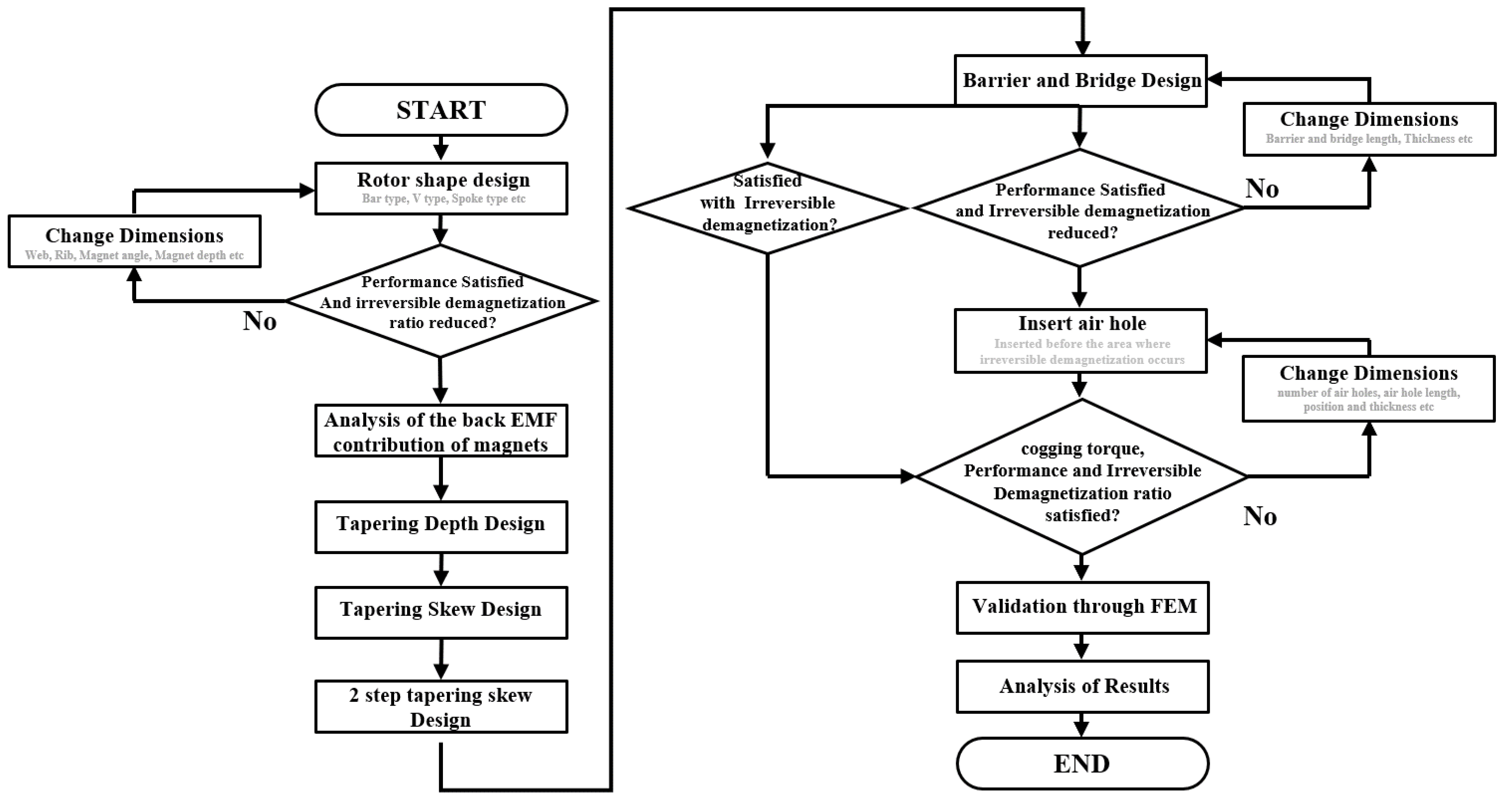
Figure 1. A rotor design process to reduce irreversible demagnetization and cogging torque.
Machines 11 00345 g001
Figure 2. A rotor design process to reduce irreversible demagnetization and cogging torque: (a) rotor of conventional motor; (b) stator of conventional motor.
Machines 11 00345 g002
Figure 3. The irreversible demagnetization area of the conventional model and the B–H curve based on Dy-free magnet at 150 °C: (a) area of irreversible demagnetization; (b) B–H curve of Dy-free magnet (second quadrant).
Machines 11 00345 g003
Figure 4. Back emf and cogging torque waveforms of the conventional model; (a) no-load back emf; (b) cogging torque.
Machines 11 00345 g004
Figure 5. Tapering structural design parameters.
Machines 11 00345 g005
Figure 6. Cogging torque and back emf according to the length of L t a p : (a) cogging torque; (b) back emf.
Machines 11 00345 g006
Figure 7. Irreversible demagnetization ratio depending on L t a p .
Machines 11 00345 g007
Figure 8. Tapering skew angles: (a) −3.5 deg, (b) 0 deg, and (c) 3.5 deg.
Machines 11 00345 g008
Figure 9. Waveform of phase back emf (skew angle 2.5 deg).
Machines 11 00345 g009
Figure 10. Two-stage skew tapering model and back emf: (a) two-stage skew tapering; (b) back emf.
Machines 11 00345 g010
Figure 11. Cogging torque waveform depending on the two-stage skew tapering structure: (a) −3.5 deg~0 deg; (b) 0 deg~3.5 deg.
Machines 11 00345 g011
Figure 12. Back emf and cogging torque depending on L t a p and tapering skew angle: (a) back emf; (b) cogging torque.
Machines 11 00345 g012
Figure 13. Irreversible demagnetization area and ratio depending on tapering skew angle: (a) irreversible demagnetization area; (b) irreversible demagnetization ratio depending on tapering skew angle.
Machines 11 00345 g013
Figure 14. Irreversible demagnetization area before and after inserting steel plates into barriers and bridges: (a) before inserting the steel plate; (b) after inserting the steel plate.
Machines 11 00345 g014
Figure 15. Cogging torque waveform before and after barrier and bridge design was applied.
Machines 11 00345 g015
Figure 16. Air hole inserted model and cogging torque and irreversible demagnetization graph: (a) air hole inserted model; (b) cogging torque and irreversible demagnetization graph.
Machines 11 00345 g016
Figure 17. Asymmetric air hole insertion model, and the graph of cogging torque and demagnetization: (a) asymmetric air hole insertion model; (b) cogging torque and irreversible demagnetization graph.
Machines 11 00345 g017
Figure 18. Rotor with asymmetric air hole structure.
Machines 11 00345 g018
Figure 19. Noload back emf and cogging torque waveforms for conventional model and final model: (a) back emf waveform; (b) cogging torque waveform.
Machines 11 00345 g019
Figure 20. Torque waveforms for the conventional model and the final model.
Machines 11 00345 g020
Figure 21. Mechanical stiffness in conventional model and final model: (a) conventional model; (b) final model.
Machines 11 00345 g021
Figure 22. Rotor and stator fabrication pictures; (a) rotor; (b) stator.
Machines 11 00345 g022
Figure 23. Pictures of the prototype and performance evaluation environment: (a) final prototype of motor applied with permanent magnet development product; (b) inverter Development; (c) semi-EMF demagnetization ratio experimental environment and diamagnetic current application device.
Machines 11 00345 g023
Figure 24. Experiment and measurement equipment for analyzing the change of back EMF due to temperature: (a) thermo-humidity chamber combined dynamo test bench; (b) temperature measurement using a temperature data logger.
Machines 11 00345 g024
Figure 25. Current test waveforms for the final model: (a) current waveform when it was operating the motor at maximum output; (b) current waveform when it was operating the motor at maximum efficiency.
Machines 11 00345 g025
Figure 26. Measurement results of counter-electromotive force reduction rate according to the temperature of the final Dy-free magnet motor prototype: (a) measurement result of no-load counter-electromotive force at 25 °C; (b) measurement result of no-load counter-electromotive force at 150 °C.
Machines 11 00345 g026
Figure 27. Waveform for conventional and proposed models; (a) back EMF waveform before the diamagnetic current; (b) diamagnetic current waveform; (c) back EMF waveform while applying the diamagnetic current.
Machines 11 00345 g027
Table 1. Specification of 35kW class hybrid traction motor with Dy-free magnet.
DescriptionValueUnit
Pole/Slot/Phase16/24/3-
Power35kW
Maximum speed/Rated speed6000/1770rpm
Maximum current/Rated current205/102.5Arms
Maximum torque/Rated torque205/102.5Nm
Stator diameter280mm
Rotor diameter200mm
Turns/Number of parallel69/8-
Dy-free magnet residual flux density1.31-
Dy-free magnet Coercive force (At 20 °C)−984kA/m
Dy-free magnet Coercive force (At 150 °C)−488kA/m
Table 2. Conventional model and final model performance comparison.
DescriptionConventional ModelFinal ModelUnit
Cogging torque (pk to pk)3.961.81Nm
Torque ripple (pk to pk)43.629.41
Noload back emf78.276.9Vrms
Irreversible demagnetization ratio0.550.61%
Table 3. Conventional model and final model performance comparison.
Conventional ModelFinal ModelUnit
Core loss140.37123.95W
Eddy current loss41.4136.93W
Copper loss630.38630.38W
Table 4. Maximum output test result of the final model.
Inverter Input VoltageRotating SpeedOutput TorqueMaximum Output
302.6 (V)2000 (rpm)187.26 (Nm)39.23 (W)
Table 5. Maximum efficiency test result.
Inverter Input VoltageInverter Input VoltageMotor OutputMaximum Efficiency
302.1 (V)17,242 (W)16.53 (W)95.91 (%)
Table 6. Measurement result of back EMF reduction rate according to the temperature of the final prototype.
Temperature Conditions20 °C150 °C
Noload back emf U phase (Vrms)48.5140.61
temperature reduction ratio (%)
(Compared to 20 °C)
-16.28
Disclaimer/Publisher’s Note: The statements, opinions and data contained in all publications are solely those of the individual author(s) and contributor(s) and not of MDPI and/or the editor(s). MDPI and/or the editor(s) disclaim responsibility for any injury to people or property resulting from any ideas, methods, instructions or products referred to in the content.