Article

Behaviour of Dissimilar Welded Connections of Mild Carbon (S235), Stainless (1.4404), and High-Strength (S690) Steels under Monotonic and Cyclic Loading

Department of Steel Structures and Structural Mechanics, Politehnica University Timisoara, 300223 Timisoara, Romania
*
Author to whom correspondence should be addressed.
Metals 2024, 14(9), 989; https://doi.org/10.3390/met14090989
Submission received: 1 August 2024 / Revised: 20 August 2024 / Accepted: 26 August 2024 / Published: 29 August 2024

Abstract

:
In the context of an increasing interest in the use of high-performance steels in the construction industry due to their superior mechanical properties, understanding the behaviour and assessing the performance of dissimilar welded connections becomes essential. When several steel grades are adopted for fabrication of the same dissipative element, dissimilar welded connections have a decisive importance regarding the seismic performance of the structural member. This paper presents the experimental results of monotonic and low-cycle fatigue (LCF) tests on dissimilar welded connections. The welded connections are designed to reproduce the loading state that occurs between the web and the flanges of dissipative links in an eccentrically braced frame, and represent combinations of S235 mild carbon steel, 1.4404 austenitic stainless steel, and S690 high-strength steel. The obtained experimental results provide a better understanding of the behaviour of dissimilar welded connections through the evaluation of their strength, ductility, and failure mechanisms, providing a basis for finite element (FE) models’ calibration for further numerical simulations. This study contributes to the evaluation of the feasibility of connections between dissimilar steels in seismic-resistant steel structures.

1. Introduction

The construction of steel structures in seismic areas raises the risk of significant post-earthquake human and financial losses, including exaggerated repair costs compared to the initial cost of construction. A possible solution is the design of seismic-resistant structures with replaceable dissipative components combined with elastic subsystems. In addition to the dissipation of seismic energy, such systems allow for easy repair of the structure following a large earthquake, due to their re-centring capability and the replaceability of the dissipative components. The application of such a design approach has been previously studied for dual eccentrically braced frames (EBFs), in which replaceable links concentrate and dissipate the seismic energy, while moment-resisting frames (MRFs) provide elastic restoring forces for re-centring [1,2,3]. The improvement in this solution is addressed in this paper, by exploiting the benefits of high-performance steels, due to their superior mechanical properties in terms of strength, toughness, and ductility. Their use in the construction industry in seismic areas could significantly contribute to increasing the safety and economic efficiency of steel structures.
Hybrid replaceable links, made from several steel grades, can provide superior performance. A previous study on hybrid links [4] in EBFs has highlighted the crucial role of the behaviour of dissimilar welded connections between link components in their seismic performance. To address this issue, this paper provides an experimental and numerical investigation of the monotonic and cyclic response of dissimilar welds.
The interest in high-performance steels in the construction industry has increased significantly due to their mechanical properties and advancements in production and processing, making them increasingly accessible. The first investigations into stainless steels were published in 1821 by the French engineer Pierre Berthier, but large-scale production of them did not become possible until 1915. In the field of structural design, the following two types of stainless steel are of interest: austenitic and duplex [5]. High-strength steels have been used in Japan since the 1960s. The extension of the applicability domain of these steels has provided a boost for performing several numerical [6,7] and experimental studies [8], which prove their potential contribution in enhancing the seismic resistance of the structures.
The severe structural damage from the Northridge (1994) and Kobe (1995) earthquakes highlighted the impact of the toughness of welded connections on the seismic performance of structures [9,10]. Subsequent experimental, microfractographic, and numerical studies have shown that failure mechanisms during low-cycle fatigue and impact tests are similarly influenced by the microstructural characteristics of welded steels [11].
The ductility and strength of dissimilar welded connections between non-alloy steel and high-strength alloy steel have been investigated both analytically and experimentally [12], confirming their applicability in structural engineering. Other studies on similar high-strength steel connections have focused on assessing the relationship between the strength and ductility of the welded connections, and related aspects such as the electrode strength, weld penetration depth, etc. [13,14,15].
The similar and dissimilar connections of stainless steels have been investigated numerically and experimentally [16,17,18] to assess the influence of welding parameters (welding process type, welding voltage and current, wire-feed speed, heat treating, etc.) on the physico-mechanical properties of connections, as well as the stress distribution in the welded material. Research results confirm the ductile response of dissimilar welded connections between carbon and stainless steels [18], while other studies specify the possible occurrence of phenomena such as hardening and embrittlement of the welded material, due to the presence of a percentage of sulphur, phosphorus, or chromium carbides in the metal bath, negatively influencing their ductility [19,20]. Several numerical studies on welded connections addressed the calibration of the modelling parameters for fillet and full-penetration welds [13,21,22].
This work describes the monotonic and cyclic response of four similar and dissimilar welded connections for combinations of three different steel grades (mild carbon, stainless, and high strength steel). Firstly, their experimental performance in terms of strength and ductility was examined, being followed by the calibration of the FE monotonic models, their numerical analysis, and the comparative overview on the numerical and experimental results. The novelty of the current research lies in its focus on the behaviour of welded connections for specific conditions arising in dissipative components (links of eccentrically braced frames) which are subjected to predominant shear loading. The seismic demands on such structural components are characterised by large strains and low-cycle fatigue. While dissipative links have been extensively studied in the past, hybrid configurations (with the web and flange fabricated from different steel grades have not been experimentally addressed to date). The experimental program described in this paper aimed at addressing this gap.

2. Experimental Tests

2.1. Experimental Program

Following an in-depth analysis of alloy and non-alloy steels for weldability and ductility considerations, three different steel grades were selected, according to EN 10020 [23], having the following nominal properties:
  • S235 J2 non-alloy steel (mild carbon steel)—a common structural steel grade, with a nominal yield strength of 235 N/mm2, and an optimal ratio of strength, ductility, and toughness at usual working temperatures.
  • Fine-grained S690 QL non-alloy steel (high-strength steel) with the nominal yield strength of 690 N/mm2, and a good weldability.
  • High-alloy steel X2CrNiMo17-12-2/AISI 316L (1.4404) (stainless steel)—an austenitic steel with a chromium content of about 16.5–18.5%, a yield strength of 210 N/mm2, similar to that of S235 carbon steel, and a nominal ductility almost double that of S235 carbon steel.
Since within the analysed structural elements, the web of the links is predominantly subjected to shear stresses, the welded connections were designed to reproduce the predominant shear-loading state which occurs between the web and the flanges of the links. The experimental specimens consist of two parts joined by fillet welds. The bottom part, the “web”, is provided with a technological slot that allows the insertion of the upper part, the “flange”, to achieve their 90° angle connection. The stability of the web and flange are ensured by stiffeners. The configuration and dimensions of the welded connections are given in Figure 1.
Fillet welds (with a weld throat a and fillet length lsFigure 1) were designed considering the measured mechanical properties of the materials, determined by tensile tests [24], and their nominal geometrical characteristics are presented in Table 1. For reasons relating to metallurgical, constructive, and technological weldability, the metal active gas (MAG) welding process was adopted, allowing for precise current control, as well as for a high-stability electric arc. A welding procedure specification (WPS) was developed for each type of welded connection. Table 1 also highlights the main specifications of the welding procedure for each combination of base metals (BM).
The nomenclature of experimental specimens (four types of welded connections, of which two were similar and two dissimilar), as well as the measured thickness of the welded plates and fillet welds, are presented in Table 2, where “M” stands for “Mild-carbon steel”, “S” stands for “Stainless steel” and “H”—for “High-strength steel”.

2.2. Loading Protocol

According to the data presented above, the four types of welded connections, of which two were similar—used as references—and two dissimilar, were designed to allow the evaluation of the cyclic performance of fillet welds, also ensuring the stability of the welded web and flange at the same time.
For each type of connection, the following tests were performed:
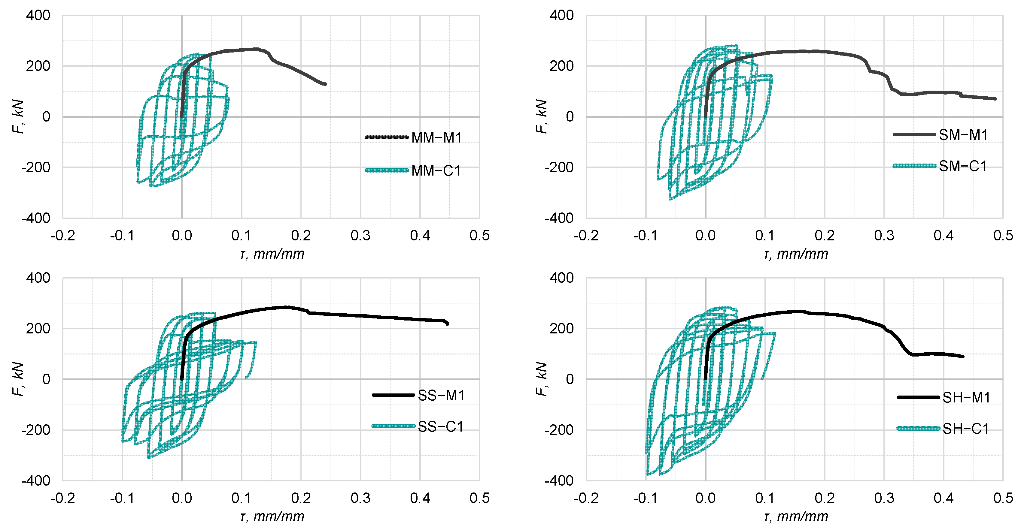
  • Two monotonic tests (specimens M1 and M2) with a 0.002 s−1 strain rate, corresponding to a crosshead speed of 0.07 mm/s.
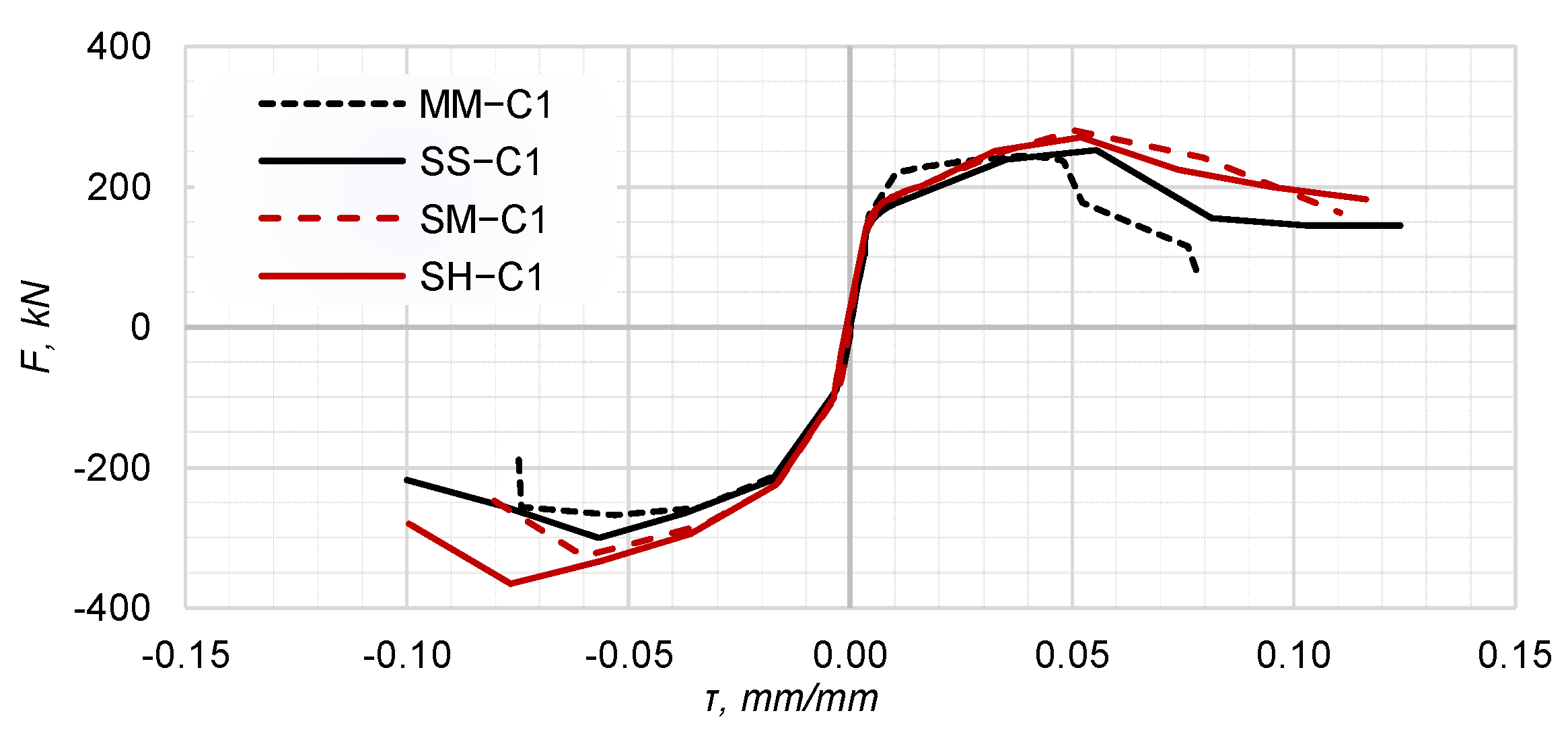
  • Four low-cycle fatigue tests (specimens C1–C4) at the same strain rate. The cyclic protocol consists of groups of two cycles at shear strains (τ) of ±0.005, ±0.02, ±0.04, …, with a progressive increase in amplitude by an increment of 0.02 mm/mm.

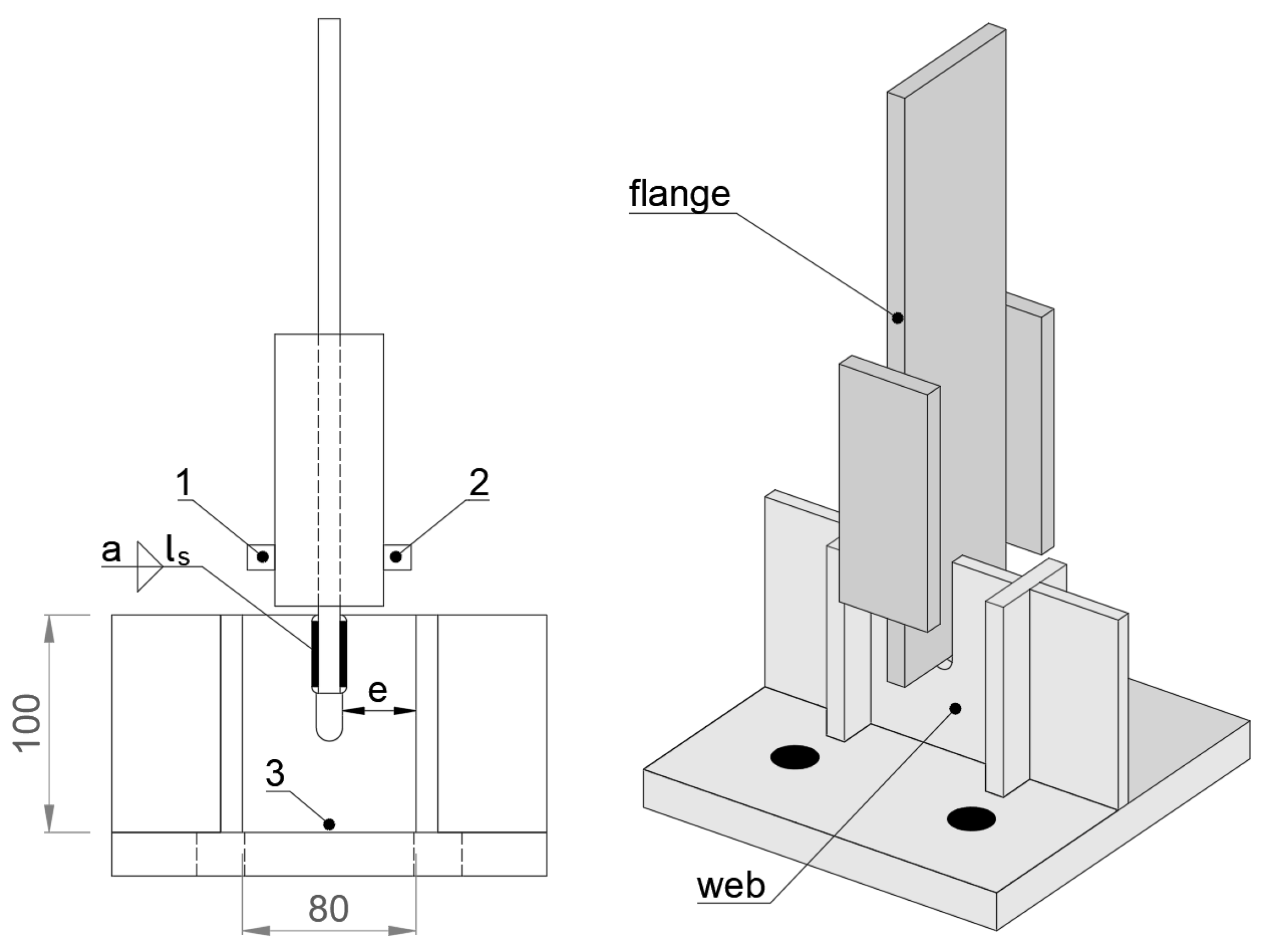
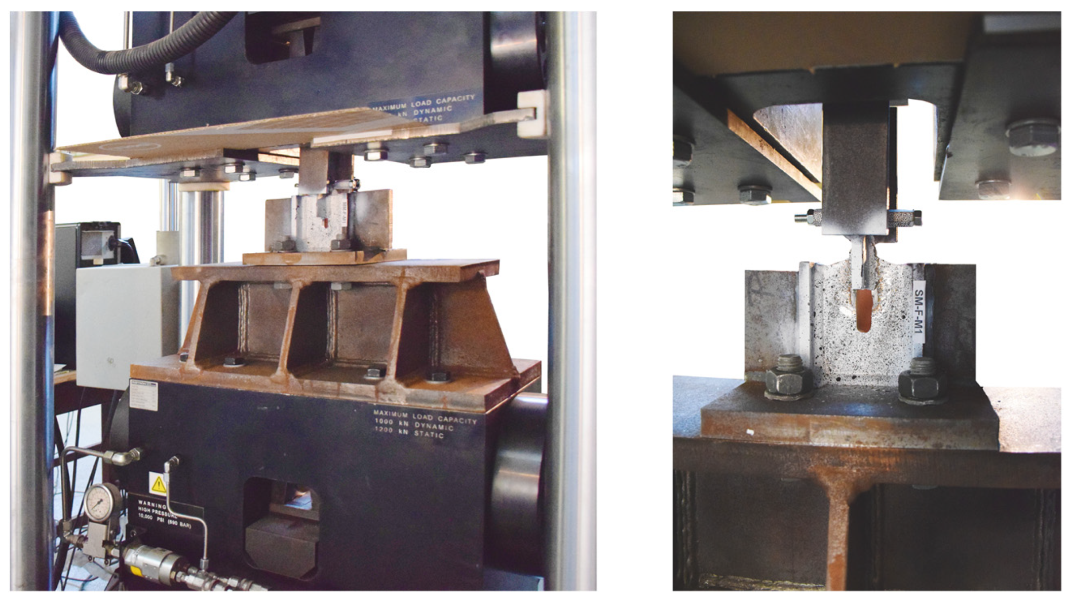
2.3. Experimental Setup and Data Processing

Tensile and low-cycle fatigue tests on welded connections were carried out by means of a servo-hydraulic testing machine (Figure 2), using a short auxiliary beam to fasten the base of the specimens.
The specimens were subjected to a monotonic load applied to the flange, in displacement control, with the force value being monitored through a load cell. The deformation was recorded using the digital image correlation technique. This solution was driven by the requirement to record only the deformations that developed along the weld and the web, excluding those of the flange of the welded connection. Thus, the average shear strain τ was calculated as the ratio d / e , where d = u 3 ( u 1 + u 2 ) / 2 ; e = 35   m m for the MM, SM, and SH specimens, or e = 34   m m for the SS specimens; and u is the vertical displacement recorded by points 1, 2 and 3, as shown in Figure 1. The main experimental results are comprised of force–shear strain curves, as well as the failure modes.

2.4. Analysis of Experimental Results

In the following section, the monotonic and low-cycle fatigue behaviour of the experimental specimens are presented. Since the results obtained for the specimens of the same typology are similar, Figure 3 shows the force–shear strain diagrams for only one specimen of each type. It can be observed that similar welded connections (MM and SS) subjected to monotonic shear tests develop a higher ultimate strength than under cyclic loading conditions, while on the contrary, dissimilar welded connections (SM and SH) recorded the highest cyclic ultimate strength. The corresponding ultimate strength values are summarised in Table 3. The cyclic hysteresis curves of the welded connections are not perfectly symmetrical because the ultimate tensile strength is limited by block tearing.
The analysis of the cyclic envelope curves allows for a general assessment of the performance of dissimilar connections compared to similar ones. Figure 4 shows a higher cyclic ductility of the specimens with a stainless steel web (SS, SH, and SM) than that of the homogeneous specimen made of S235 non-alloy steel (MM), but the ratio between the ductility of the connections is not proportional to the corresponding ratio of elongation at rupture of the BM. The strength degradation is more gradual for the stainless steel web specimens in comparison with the MM specimens, as could be noted from the descending slope of the envelope curves.
As depicted in Figure 5, the post-test visual analysis of the experimental specimens allowed to identify three main failure modes. The similar welded connection made of mild carbon steel subjected to monotonic loading failed by web yielding, followed by fracture in the BM in the weld proximity, in a block tearing pattern (1). The same connection, during the LCF test, failed by web yielding followed by fracture in the heat-affected zone (HAZ) or in the weld (2). The similar welded connections made of the SS stainless steel recorded a mixed failure mode (3), characterised by yielding in the BM, followed by fracture in the HAZ or weld and fracture in the BM transverse to the loading direction, in both monotonic and cyclic tests. Specimens with dissimilar welds, SM and SH, subjected to monotonic loading, failed in mode (2) and in mode (3) in low-cycle fatigue tests. The failure modes for the analysed specimens are summarised in Table 4.
The average values of ultimate strength F u for each welded connection category were analysed and are presented in Table 3. For specimens subjected to cyclic loading, ultimate strength values ( F u , C + ) are reported for the positive branch of the hysteresis curve, because the failure of all specimens occurred in tension. According to the data presented in Table 3, the ultimate strengths recorded for homogeneous specimens with similar welds subjected to cyclic loading are about 4% lower than under monotonic loading, while for dissimilar welds the ultimate strength during the LCF tests is 3.0 to 4.1% higher.
Table 4 reveals the ultimate shear strain τ r M , corresponding to the 50% drop of the maximum strength during monotonic tests, and the maximum shear strain τ r C reached in LCF tests, the ratios of these strains and the failure modes of specimens under monotonic and cyclic loading conditions.
It could be observed that in all cases the ductility under cyclic loading represents only 23–34% of the one under monotonic loading. As the homogeneous specimen made of mild carbon steel MM showed the lowest ductility, the ductility of all other specimens were normalised by dividing by the ductility of the MM specimen. The homogeneous stainless steel specimen SS showed the highest monotonic performance, both in terms of ultimate strength and ductility; while under cyclic loading conditions, the specimens with dissimilar welds performed the best. The ductility of the SS specimens which failed in mode 3 under monotonic loading (by cracking in the BM) was identified as the highest when compared to the MM specimens, while failure mode 2 of the specimens with dissimilar welds, which involve fracture in the weld, contributed to the reduction in ductility. The use of an improper welding wire with a high carbon content led to a more brittle weld failure, but also increased its strength. The latter aspect compensated to some extent for the brittleness of the weld, leading to a satisfactory behaviour of the dissimilar welded connections.

3. Numerical Simulations

3.1. Material Constitutive Model

The material properties of the selected steel grades were determined from a series of tensile tests on BM with different plates thicknesses. Tensile specimens were designed according to ISO 6892-1 [25], and the tensile tests were carried out in strain-control, with a quasi-static strain rate of 0.00025 s−1 up to the yield point, and a strain rate of 0.002 s−1 thereupon, up to failure. A series of Charpy tests allowed for a toughness assessment of the steels. A comparison between nominal and experimental values is presented in Table 5.
The calibration of the material model included the following steps:
  • Experimental data analysis and engineering stress–strain curves processing, as well as identifying the main physico-mechanical characteristics: the yield strength and the corresponding strain (fy, εy), the ultimate tensile strength and corresponding strain (fu, εu), and the elongation at fracture and corresponding strength (fr, εr).
  • Computing of the true stress–strain curves based on engineering ones. For the range between the yielding and ultimate strengths, the relationships stipulated in Annex C of EN 1993-1-5:2006 were adopted [29], in order to obtain the true stress–strain values:
σ t r u e = σ ( 1 + ε )
ε t r u e = l n ( 1 + ε )
The post-necking true stress–strain curve values were determined by extrapolation, being further calibrated through trial and error iterative simulations in the Abaqus CAE 2020 software [30]. The FE model of the S235 tensile specimen is presented in Figure 6. The engineering and true stress–strain curves obtained by iterative numerical simulations for the three steel grades: S235, S690, and 1.4404, are presented in Figure 7. As material damage was not explicitly modelled, it was considered in a simplified way by allowing for a descending branch of the true stress–strain curve at ultimate strains. It can be observed that the ultimate true strains are considerably larger than the ultimate engineering strains. This is due to the fact that engineering strains are averaged over the initial gauge length of the tensile specimen, while the true ones are obtained over an infinitesimal length of the specimen.

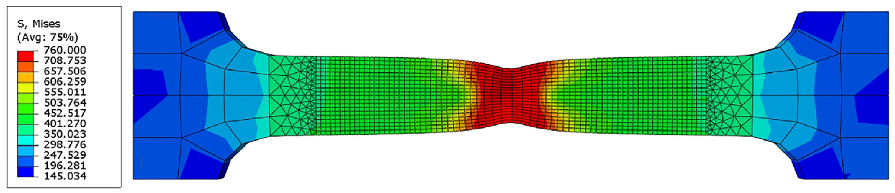
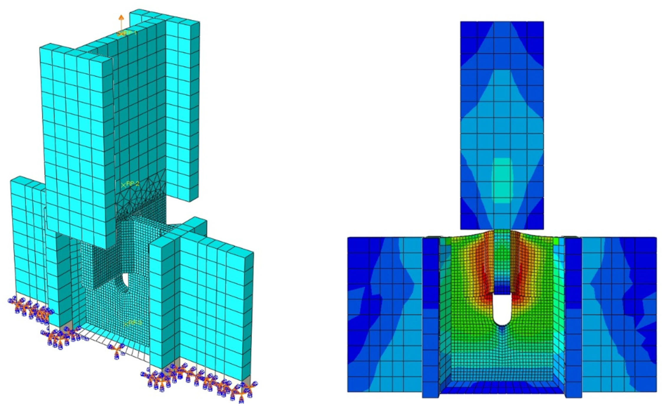
3.2. FE Modelling of Welded Connections

Numerical simulations of monotonic shear tests on welded connections were performed in the FEA software Abaqus CAE 2020. The welded connections were modelled with 3D deformable solid elements, meshed with C3D8R finite elements (8-node linear brick, reduced integration, hourglass control). Mesh refinement was adjusted based on a previous sensitivity study [30], to provide adequate accuracy of the numerical results and a reasonable computing time. The boundary conditions were modelled in the Step and Interaction modules of the Abaqus CAE 2020 software, the bottom surface of the model being fully fixed (Figure 8). The monotonic loading indicated by an arrow in Figure 8, was applied as a 5 mm displacement of the flange in the Y direction, reproducing the crosshead action. The output results were extracted from points similar to those monitored in the experimental tests, in order to ensure the comparability of the results. All the components of the assembly, including the welds, were connected to each other by “Tie” constraints which block all the relative displacements of the adjacent nodes. Numerical analyses were performed using the Abaqus/Implicit solver with the Quasi-Static option, for improved analysis convergency. In the elastic range the material model was characterised by the modulus of elasticity and the Poisson effect. Material plasticity was taken into account using the Von Mises yielding criterion.
In the FE numerical analysis, the following modelling assumptions were adopted:
  • For an accurate simulation of the experimental tests, the measured dimensions of the components (plates and welds) of the welded connections were considered;
  • In order to simulate the partial weld penetration due to melting of the BM, the weld throats were extended in the section by 2 mm (Figure 9), based on approximate measurements of the experimental specimens, while keeping the measured length ls;
  • After fabrication of the bottom and the upper parts of the welded connections, the manufacturing company used slag blasting. Abrasive blasting, in addition to the surface-finishing effect, also could act as a shot-peening process conducting to nanocrystallisation of a surface layer of the material, which can lead to hardening of a certain depth of the material surface [31,32]. Previous studies [33,34] evaluated an increase of 10 to 124% of the mechanical properties of the steels subjected to the mechanical methods of surface treatment, depending on the parameters of the blasting process—material, pressure, duration, etc. The thickness of the hardened layer also depends on the same process parameters, which, according to [35], can range from tens of nanometers to hundreds of micrometers, directly proportional to the kinetic energy induced by blasting. By extrapolation, based on the values provided in [36], and the thicknesses of the used plates, an increase of about 6% in the strength of the materials used was deducted. Thus, the yield limit and tensile strength of the material were multiplied by a factor k = 1.06, which takes into account the hardening of the steel after slag blasting treatment.
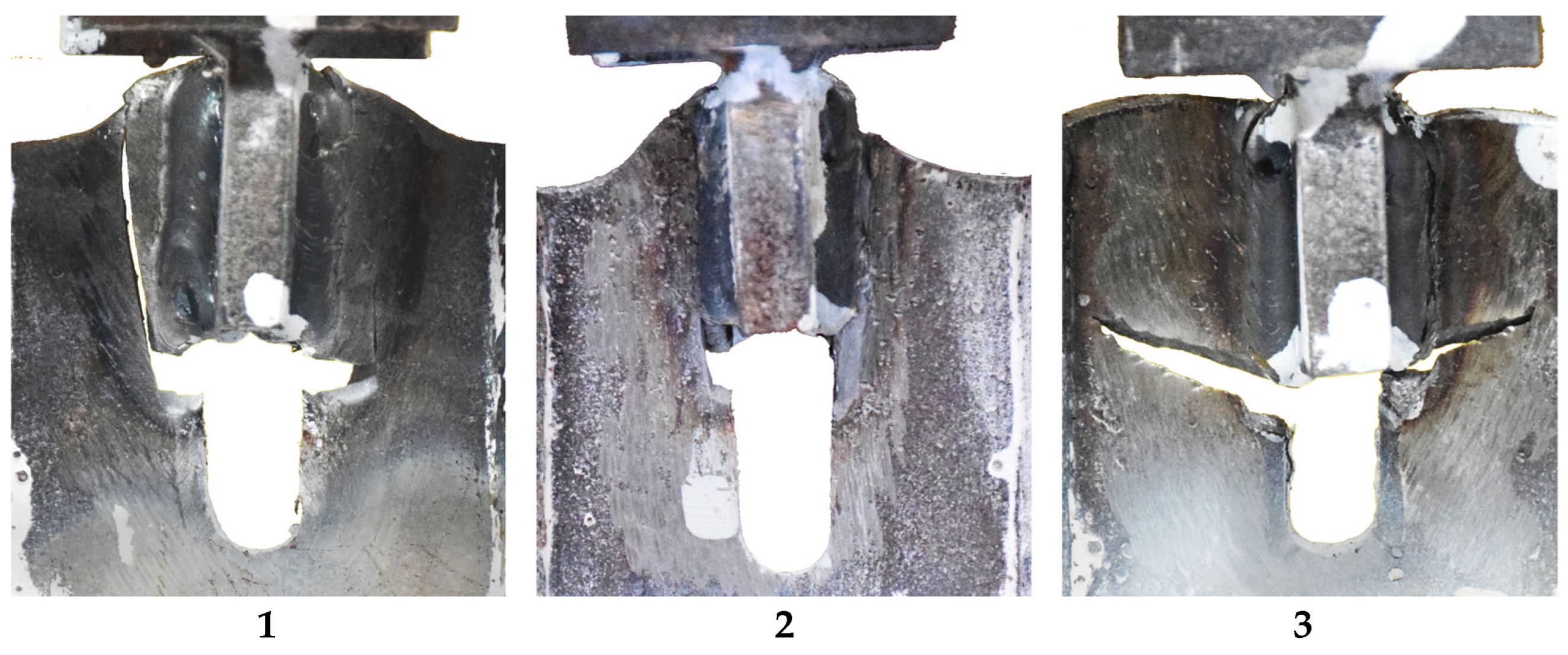
  • As mentioned in Section 2.4, the specimens with stainless steel web failed by fracture in the weld. Following fractographic analyses and the impact tests performed on the welds [20], it was concluded that a chromium carbide precipitation occurred, leading to the embrittlement of the weld. This phenomenon can be due to the presence of a percentage of non-alloy steel in the metal bath. A possible reason for this phenomenon would be the use of a different type of welding wire than the one provided in the welding procedure specification. The FE analyses on the SS and MS connections using the mechanical properties of the wires provided in the WPS (Table 1) confirmed this conclusion, the numerical results indicating a significantly reduced strength compared to the experimental one. In order to calibrate the numerical models SS and SM and to reproduce the hardening of the corresponding welds, the mechanical characteristics of the welded material have been determined by means of a series of trial-and-error calibrations, which are able to ensure a reliable numerical simulation of the welded connection response under monotonic shear tests (Table 6). For the MM and SH numerical models, the maximum values of the yield and ultimate strengths provided in the product standards of the G3Si1/ER70S-6 and AWS A5.28/ER100S-G welding wires were used.

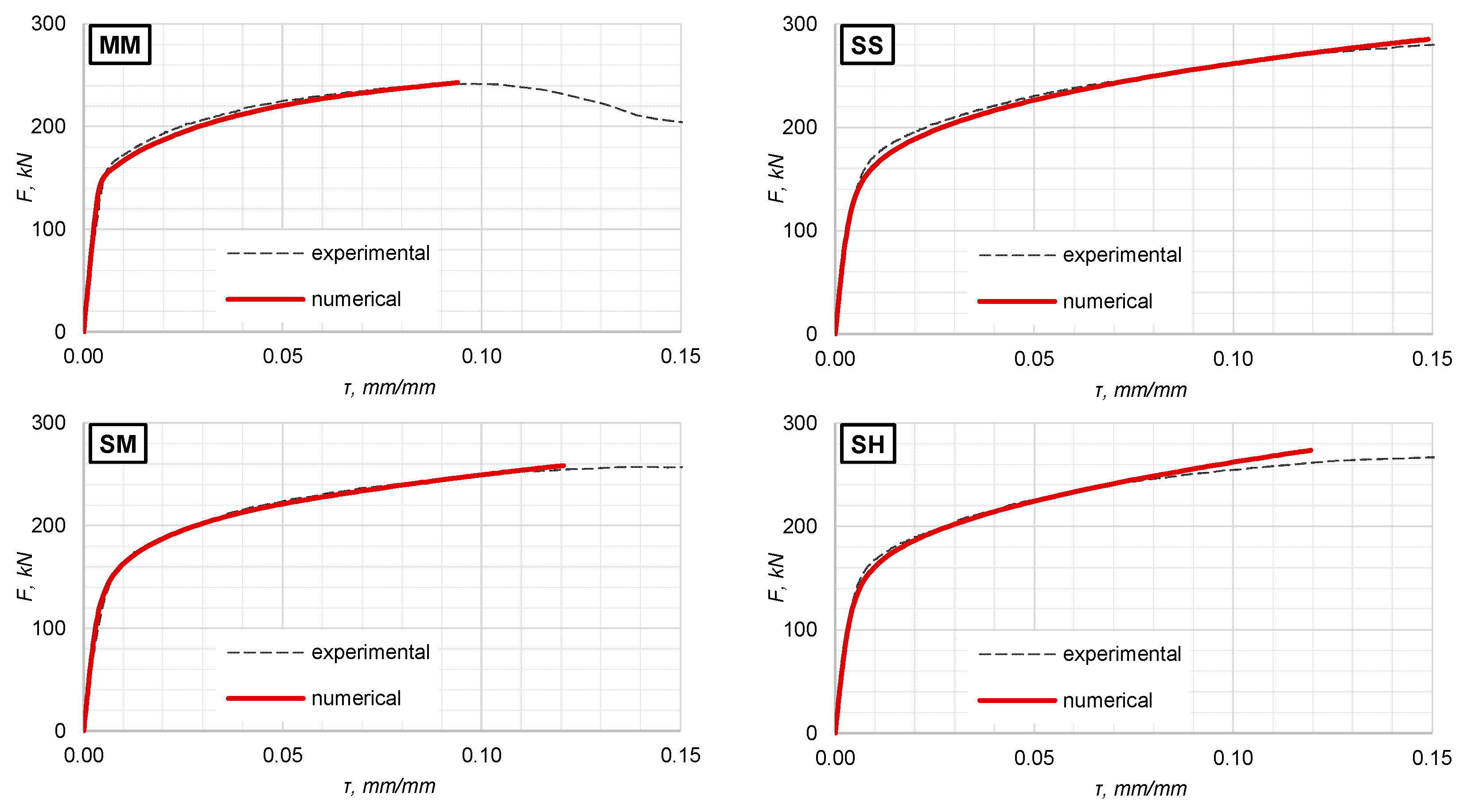
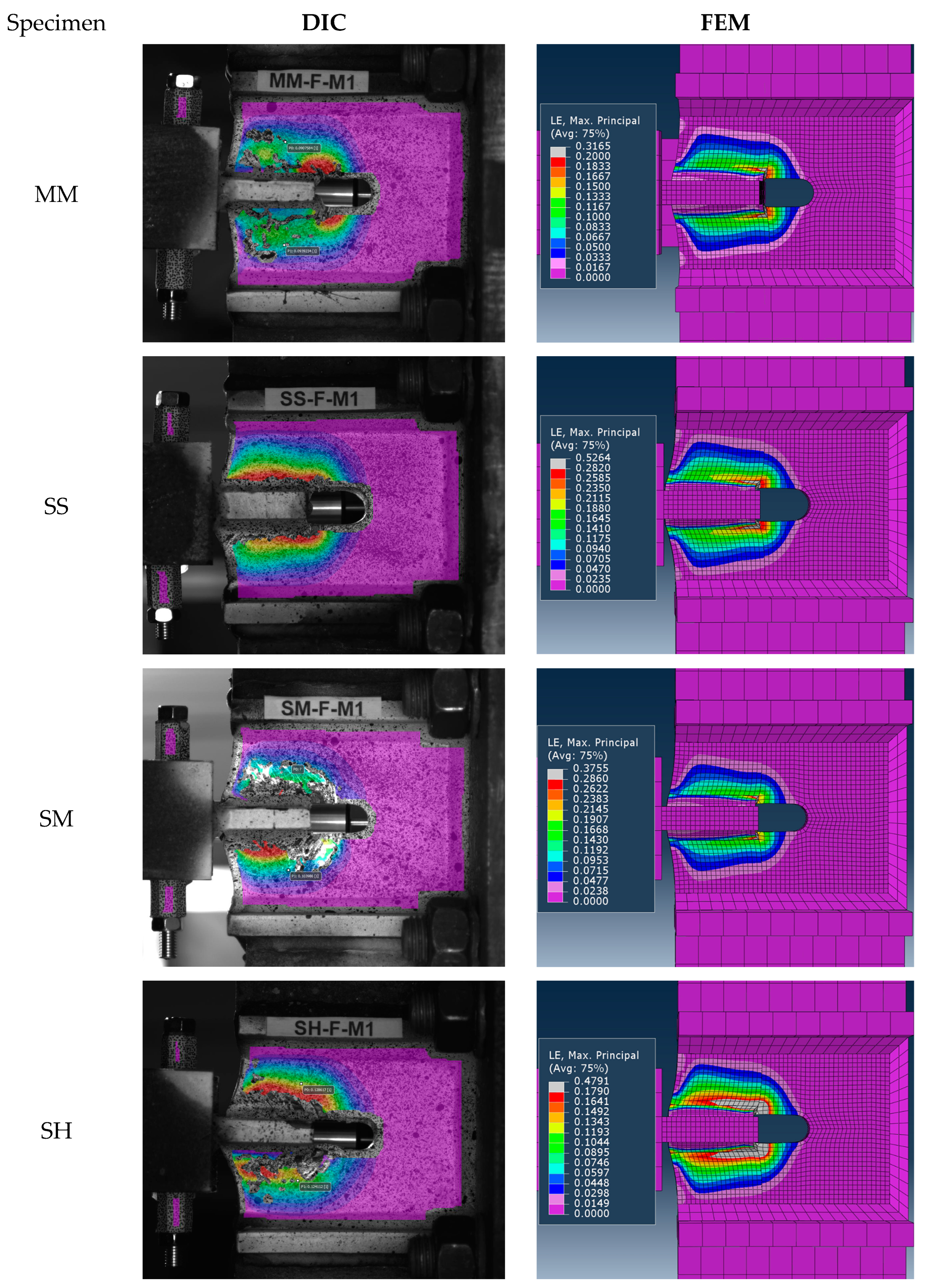
3.3. Analysis of Numerical Results

The numerical analysis of the model developed with the above-mentioned assumptions provided output results in terms of force–shear strain of the web, which shows a good correlation with the experimental results up to ultimate strength. As depicted in Figure 10, connection stiffness, as well as the elasto-plastic range of the numerical responses of the models, reproduce the experimental ones with a high degree of fidelity.
Figure 11 presents an explicit comparison between the principal logarithmic strain field distribution in the web of the welded connections recorded by the digital image correlation system, and those obtained by FE analysis. The numerical simulations proved to be highly consistent with the experimental distribution of plastic strain, validating the FE model accuracy. However, the numerical distribution reports a wider range of values of plastic strain, exceeding those recorded experimentally, which were limited by the loss of the pattern due to plastic deformations of the web and the exfoliation of the paint layer during the tests, allowing to monitor only the regions where the layer remained intact. The numerical simulations overcame the experimental limitations, allowing a detailed analysis of stress concentrations in the web of welded connections and especially in weld proximity area. This advanced analysis also provides a thorough view on the failure modes observed in experimental phase.
The calibration of the numerical model and FE analysis allow for a more rigorous approach in the design process of welded connections. Numerical simulations of the welded connections under different loading protocols contribute significantly to a better understanding of their behaviour and provide the tools for improving the performance and ductility of structural elements.

4. Conclusions

The monotonic and cyclic responses of homogeneous and dissimilar welded connections under shear loading were presented in this paper. The experimental tests on the welded specimens showed that all welded connections have a cyclic ductility about three times lower than that of the monotonic one, and stainless steel web connections have a higher cyclic performance than those with web made of non-alloy mild carbon steel. The failure mode analysis emphasised that the welded connections with 1.4404 stainless steel web are prone to brittle failure by fracture in the weld throat, despite the higher ductility compared to the S235 carbon steel connections. This behaviour is attributed to weld embrittlement due to mismatch of welding consumables and should not be generalised. At the same time, failure mode 3 (by fracture in the BM) can be characterised as a favourable mode of failure, based on the relatively high ductility of the corresponding specimens, both under monotonic and cyclic loadings. Failure mode 2 (by fracture in the weld), specific to hybrid specimens SM and SH with dissimilar welds subjected to monotonic tests, explains their relatively low ductility values. To exploit the benefits of high-performance steels, a very accurate selection of welding parameters and filler materials is needed, in order to avoid such phenomena as embrittlement, which lead to a decrease in the dissimilar welded connections’ performance, in terms of strength and ductility. The experimental tests served as a basis for the calibration of numerical models, which are a useful tool for optimising the design of dissimilar welded connections. The formation of brittle structures in the weld as a result of the use of improper welding wire for the SS and SM connections required the iterative adjustment of the mechanical properties of the filler material in the numerical simulations. Further studies will address the numerical simulation of the cyclic behaviour of welded connections and FE damage modelling, as well as the calibration of the parameters that characterise the crack initiation and propagation.

Author Contributions

Conceptualisation, A.S.; methodology, A.S., A.E. and I.B.; validation, A.S. and A.E.; formal analysis, A.E., A.S. and I.B.; investigation, A.S., A.E. and I.B.; data curation, A.E., A.S. and I.B.; writing—original draft preparation, A.E.; writing—review and editing, A.S. and I.B.; visualisation, A.E.; supervision, A.S.; project administration, A.S.; funding acquisition, A.S. All authors have read and agreed to the published version of the manuscript.

Funding

This research was supported by a grant of the Romanian Ministry of Education and Research, CCCDI–UEFISCDI, project number PN-III-P2-2.1-PED-2019-5427, within PNCDI III.

Data Availability Statement

The original contributions presented in the study are included in the article, further inquiries can be directed to the corresponding author.

Conflicts of Interest

The authors declare no conflicts of interest.

References

  1. Stratan, A.; Dubina, D. Bolted Links for Eccentrically Braced Steel Frames. In Proceedings of the Fifth AISC/ECCS International Workshop “Connections in Steel Structures V. Behaviour, Strength & Design”; Bijlaard, F.S.K., Gresnigt, A.M., van der Vegte, G.J., Eds.; Delft University of Technology: Delft, The Netherlands, 2004; pp. 223–232. [Google Scholar]
  2. Dubina, D.; Stratan, A.; Dinu, F. Dual High-strength Steel Eccentrically Braced Frames with Removable Links. Earthq. Eng. Struct. Dyn. 2008, 37, 1703–1720. [Google Scholar] [CrossRef]
  3. Ioan, A.; Stratan, A.; Dubină, D.; Poljanšek, M.; Molina, F.J.; Taucer, F.; Pegon, P.; Sabău, G. Experimental Validation of Re-Centring Capability of Eccentrically Braced Frames with Removable Links. Eng. Struct. 2016, 113, 335–346. [Google Scholar] [CrossRef]
  4. Ene, A.; Stratan, A. Pre-Test Numerical Modelling of Stainless Steel and Hybrid Links. In Proceedings of the 10th International Conference on Behaviour of Steel Structures in Seismic Areas; Mazzolani, F.M., Dubina, D., Stratan, A., Eds.; Lecture Notes in Civil Engineering; Springer International Publishing: Cham, Switzerland, 2022; Volume 262, pp. 125–132. ISBN 978-3-031-03810-5. [Google Scholar]
  5. Gedge, G. Structural Uses of Stainless Steel—Buildings and Civil Engineering. J. Constr. Steel Res. 2008, 64, 1194–1198. [Google Scholar] [CrossRef]
  6. Ho, H.C.; Xiao, M.; Hu, Y.F.; Guo, Y.B.; Chung, K.F.; Yam, M.C.H.; Nethercot, D.A. Determination of a Full Range Constitutive Model for High Strength S690 Steels. J. Constr. Steel Res. 2020, 174, 106275. [Google Scholar] [CrossRef]
  7. Dubina, D.; Stratan, A.; Vulcu, C.; Ciutina, A. High Strength Steel in Seismic Resistant Building Frames. Steel Constr. 2014, 7, 173–177. [Google Scholar] [CrossRef]
  8. Shi, G.; Wang, M.; Bai, Y.; Wang, F.; Shi, Y.; Wang, Y. Experimental and Modeling Study of High-Strength Structural Steel under Cyclic Loading. Eng. Struct. 2012, 37, 1–13. [Google Scholar] [CrossRef]
  9. Ricles, J.M.; Fisher, J.W.; Lu, L.-W.; Kaufmann, E.J. Development of Improved Welded Moment Connections for Earthquake-Resistant Design. J. Constr. Steel Res. 2002, 58, 565–604. [Google Scholar] [CrossRef]
  10. Kotecki, D.J.; Narayanan, B. Welding Consumable Developments in the Aftermath of the Northridge Earthquake. Weld. World 2005, 49, 42–46. [Google Scholar] [CrossRef]
  11. Kermajani, M.; Ghaini, F.M.; Miresmaeili, R.; Aghakouchak, A.A.; Shadmand, M. Effect of Weld Metal Toughness on Fracture Behavior under Ultra-Low Cycle Fatigue Loading (Earthquake). Mater. Sci. Eng. A 2016, 668, 30–37. [Google Scholar] [CrossRef]
  12. Dubina, D.; Stratan, A.; Muntean, N.; Grecea, D. Dual-Steel T-Stub Behavior under Monotonic and Cyclic Loading. In Proceedings of the International Workshop on Connections in Steel Structures, Chicago, IL, USA, 23–25 June 2008. [Google Scholar]
  13. Khurshid, M.; Barsoum, Z.; Mumtaz, N.A. Ultimate Strength and Failure Modes for Fillet Welds in High Strength Steels. Mater. Des. 2012, 40, 36–42. [Google Scholar] [CrossRef]
  14. Stroetmann, R.; Kästner, T. Welds on High-Strength Steels—Influence of the Welding Process and the Number of Layers. In Stability and Ductility of Steel Structures 2019: Proceedings of the International Colloquia on Stability and Ductility of Steel Structures (SDSS 2019), September 11–13, 2019, Prague, Czech Republic, 1st ed.; Wald, F., Jandera, M., Eds.; CRC Press: London, UK, 2019; pp. 1103–1110. ISBN 9780429320248. [Google Scholar] [CrossRef]
  15. Kuhlmann, U.; Günther, H.-P.; Rasche, C. Investigations of Strength and Ductility of Welded High Strength Steel (HSS) Connections. In Design, Fabrication and Economy of Welded Structures; Elsevier: Amsterdam, The Netherlands, 2008; pp. 411–418. ISBN 978-1-904275-28-2. [Google Scholar]
  16. Biswas, A.R.; Chakraborty, S.; Ghosh, P.S.; Bose, D. Study of Parametric Effects on Mechanical Properties of Stainless Steel (AISI 304) and Medium Carbon Steel (45C8) Welded Joint Using GMAW. Mater. Today Proc. 2018, 5, 12384–12393. [Google Scholar] [CrossRef]
  17. Khan, M.; Dewan, M.W.; Sarkar, M.Z. Effects of Welding Technique, Filler Metal and Post-Weld Heat Treatment on Stainless Steel and Mild Steel Dissimilar Welding Joint. J. Manuf. Process. 2021, 64, 1307–1321. [Google Scholar] [CrossRef]
  18. Kumar Singh, D.; Sahoo, G.; Basu, R.; Sharma, V.; Mohtadi-Bonab, M.A. Investigation on the Microstructure—Mechanical Property Correlation in Dissimilar Steel Welds of Stainless Steel SS 304 and Medium Carbon Steel EN 8. J. Manuf. Process. 2018, 36, 281–292. [Google Scholar] [CrossRef]
  19. Ananthapadmanaban, D.; Seshagiri Rao, V.; Abraham, N.; Prasad Rao, K. A Study of Mechanical Properties of Friction Welded Mild Steel to Stainless Steel Joints. Mater. Des. 2009, 30, 2642–2646. [Google Scholar] [CrossRef]
  20. Dașcău, H.; Duma, I.; Mnerie, G.V. Microstructural Hardness Evaluation in the HAZ of Welded Joints Realized out of Austenitic (316L) and Carbon Steel (S235). In Proceedings of the 13 edition of the International Conference “Innovative Technologies for Joining Advanced Materials–TIMA22”, Timișoara, Romania, 24–25 November 2022. [Google Scholar]
  21. Ghimire, A.; Wald, F.; Vild, M.; Kabeláč, J. Numerical Design Calculation of the Fillet Weld Resistance. Weld. World 2024, 68, 441–458. [Google Scholar] [CrossRef]
  22. Ghimire, A.; Wald, F.; Vild, M.; Kabeláč, J. Numerical Design Calculation of the High-Strength Steel Welds. Eng. Struct. 2024, 300, 117201. [Google Scholar] [CrossRef]
  23. EN 10020:2000; Definition and Classification of Grades of Steel. European Commission: Brussels, Belgium, 2000.
  24. Ene, A.; Both, I.; Abrudan, O.; Stratan, A.; Daşcău, H.F.; Sîrbu, N.A. Experimental Investigation of Monotonic and Cyclic Behaviour of High-Performance Steels. Key Eng. Mater. 2023, 953, 13–20. [Google Scholar] [CrossRef]
  25. ISO-6892-1:2019; Metallic Materials—Tensile Testing. Part 1: Method of Test at Room Temperature. ISO: Geneva, Switzerland, 2019.
  26. EN 10025-2:2004; Hot Rolled Products of Structural Steels. Part 2: Technical Delivery Conditions for Non-Alloy Structural Steels. European Commission: Brussels, Belgium, 2004.
  27. EN 10088-4:2009; Stainless Steels. Part 4: Technical Delivery Conditions for Sheet/Plate and Strip of Corrosion Resisting Steels for Construction Purposes. European Commission: Brussels, Belgium, 2009.
  28. EN 10025-6:2004; Hot Rolled Products of Structural Steels. Part 6: Technical Delivery Conditions for Flat Products of High Yield Strength Structural Steels in the Quenched and Tempered Conditions. European Commission: Brussels, Belgium, 2004.
  29. EN 1993-1-5:2006; Eurocode 3—Design of Steel Structures—Part 1-5: Plated Structural Elements. European Commission: Brussels, Belgium, 2006.
  30. Ene, A.; Both, A. Monotonic and Cyclic Modelling of Structural Steel for Finite Element Analysis. Key Eng. Mater. 2023, 953, 21–29. [Google Scholar] [CrossRef]
  31. Yang, L.; Tao, N.R.; Lu, K.; Lu, L. Enhanced Fatigue Resistance of Cu with a Gradient Nanograined Surface Layer. Scr. Mater. 2013, 68, 801–804. [Google Scholar] [CrossRef]
  32. Olugbade, T.O.; Lu, J. Literature Review on the Mechanical Properties of Materials after Surface Mechanical Attrition Treatment (SMAT). Nano Mater. Sci. 2020, 2, 3–31. [Google Scholar] [CrossRef]
  33. Zhou, J.; Xu, X.; Sun, Z.; Retraint, D.; Zhang, X.; Xue, H. Predicting Gradient Mechanical Behaviour of a Shot-Peened Structure. Int. J. Solids Struct. 2023, 262–263, 112063. [Google Scholar] [CrossRef]
  34. Kirk, D. Ductility and Strength Properties of Shot Peened Surfaces. The Shot Peener Magazine 2006. Available online: https://web.archive.org/web/20240612125748/https://www.shotpeener.com/library/pdf/2006051.pdf (accessed on 12 June 2024).
  35. Soady, K.A. Life Assessment Methodologies Incoroporating Shot Peening Process Effects: Mechanistic Consideration of Residual Stresses and Strain Hardening Part 1—Effect of Shot Peening on Fatigue Resistance. Mater. Sci. Technol. 2013, 29, 637–651. [Google Scholar] [CrossRef]
  36. Maleki, E.; Unal, O.; Reza Kashyzadeh, K.; Bagherifard, S.; Guagliano, M. A Systematic Study on the Effects of Shot Peening on a Mild Carbon Steel: Microstructure, Mechanical Properties, and Axial Fatigue Strength of Smooth and Notched Specimens. Appl. Surf. Sci. Adv. 2021, 4, 100071. [Google Scholar] [CrossRef]
Figure 1. Geometric configuration of the experimental specimens (dimensions in mm).
Metals 14 00989 g001
Figure 2. Experimental setup and a specimen subjected to test.
Metals 14 00989 g002
Figure 3. Comparison between monotonic and cyclic response of welded connections.
Metals 14 00989 g003
Figure 4. Envelope curves for the cyclic diagrams of each type of welded connection.
Metals 14 00989 g004
Figure 5. Typical failure modes of the welded specimens. (1) Yielding followed by fracture in the BM next to the weld in a block tearing pattern. (2) Yielding followed by fracture in the HAZ or welded material in a block tearing pattern. (3) Mixed failure mode yielding of the BM, followed by a fracture in the HAZ or welded material and fracture in the BM transverse to the loading direction.
Metals 14 00989 g005
Figure 6. FE modelling of the S235 mild carbon steel specimen made of 8 mm thick plate, subjected to monotonic loading.
Metals 14 00989 g006
Figure 7. Engineering and true stress–strain diagrams for the investigated steels.
Metals 14 00989 g007
Figure 8. FE model of the MM specimen and the Von Mises stress distribution field resulted from analysis.
Metals 14 00989 g008
Figure 9. Welds modelling assumption for FE model calibration.
Metals 14 00989 g009
Figure 10. Numerical and experimental response of the welded connections subjected to monotonic shear tests, in terms of force and shear strain.
Metals 14 00989 g010
Figure 11. Principal logarithmic strain field distribution at ultimate strength: obtained by means of digital image correlation (DIC) technique (left) and resulted from FE numerical analysis (right).
Metals 14 00989 g011
Table 1. Main characteristics of welds according to the welding procedure specifications (WPS).
Base Metalsa, mmls, mmWelding WireShielding Gas
S235 + S235438EN ISO 14341-A: G3Si1EN ISO 14175:C1
(min 99.7% CO2)
1.4404 + 1.4404336EN 12073: T 19 12 3 L R C3EN ISO 14175:M21 (82%Ar + 18%CO2)
1.4404 + S235336EN ISO 17633-A: T 23 12 2 L P M21 1EN ISO 14175:M21 (82%Ar + 18%CO2)
1.4404 + S690336EN ISO 16834-A: Mn3Ni1CrMoEN ISO 14175:M21 (82%Ar + 18%CO2)
Table 2. Welded connections nomenclature.
Specimen IDWebFlangesa, mmls, mm
Steel GradePlate ThicknessSteel GradePlate Thickness
MMS2358.09S2359.854.139
SS1.44047.951.440411.753.736
SM1.44047.95S2359.853.636.5
SH1.44047.95S69010.553.837.8
Table 3. Ultimate strength of the welded connections, mean of tests.
Specimen ID F u , M (kN) F u , C + (kN) F u , C + F u , M / F u , M + (%)
MM254.0244.2−3.86
SS279.6267.1−4.47
SM265.8273.83.01
SH263.3274.24.14
Table 4. Mean values of the fracture strain, their corresponding ratios and failure modes for each type of welded connection.
Specimen IDFailure Mode τ r , M (mm/mm) τ r , C (mm/mm) τ r C / τ r M τ r M S / τ r M ( M ) τ r C S / τ r C ( M )
M *C **
MM120.2480.0840.341.001.00
SS330.4480.1040.231.811.24
SM230.4250.1140.271.711.36
SH230.3210.1060.331.291.26
M * monotonic loading. C ** cyclic loading. (S)—strain of the specimens with stainless steel web (SS, SM and SH). (M)—strain of the specimens with mild carbon steel web (MM).
Table 5. The nominal and experimental mechanical properties of the investigated steels.
Specimen IDfy/Rp0.2 (MPa)fu (MPa)A (%)KV (J)
St *Exp **StExpStExpStExp
M8 (S235 J2)235329360–5104802432.127 (−20 °C)57
M10 (S235 J2)3264672431.5-
S8—T (1.4404)220311520–7206064551.660 (+20 °C)202
S12—T (1.4404)3196064551.8-
H10 (S690 QL)690760770–9408381417.140 (−20 °C)-
* St—nominal values provided in the material standards (EN 10025-2:2004 [26] for non-alloy steels, EN 10088-4:2009 [27] for stainless steels, EN 10025-6:2004 [28]—for high-strength steels; ** Exp—the properties obtained from the experimental tests on BM.
Table 6. Mechanical properties of the welded material assumed within FE model calibration process.
Specimen IDfy (N/mm2)Rm (N/mm2)A (%)
MM53864024
SS78080020
SM78080020
SH72078016
Disclaimer/Publisher’s Note: The statements, opinions and data contained in all publications are solely those of the individual author(s) and contributor(s) and not of MDPI and/or the editor(s). MDPI and/or the editor(s) disclaim responsibility for any injury to people or property resulting from any ideas, methods, instructions or products referred to in the content.

